
Chapter 14: Making a Custom Rig for Our Alien Plant with Control Rig
In the previous chapter, we completed a more complex skeleton for the robot. Now we'll move on to the next stage of creating an animation-friendly rig in Unreal Engine (UE). Creating a skeleton and skinning it are the first steps toward making our 3D model or character animatable. We will learn how to add controllers that make it easier for animators to animate it.
With good controllers on top of a skeleton, it makes it possible for animators to edit, organize, and refine animations in a much more effective way. The general process of setting up a more complex 3D model to be animatable is called rigging it.
Rigging has three general steps:
- Creating a skeleton
- Skinning the 3D model to the skeleton
- Creating controllers to drive or control our skeleton, otherwise called creating an animation rig
Until recently, there weren't any effective tools in UE to create and manage animation rigs and animation, but with the development of Control Rig and the tools around it, it has become possible to create and animate these rigs effectively natively inside UE5 itself.
There's no longer a need to do this in third-party software, such as Blender or Maya. In the following chapters, we will learn how this pipeline works in UE5 so you can create new animations or edit existing ones freely.
In this chapter, we will cover the following:
- Introduction to the Control Rig Editor
- Creating basic Control Rig controllers
- Controlling the Alien Plant skeleton with the controllers
Technical requirements
The following are the technical skills and software you need to complete this chapter:
- A computer that can run basic 3D animation software.
- You need to have Blender installed for free from https://www.blender.org/ (at the time of writing). The Blender version used in this chapter is 3.1.2, but some older and newer versions will also work.
- A basic understanding of how to navigate the 3D user interface. If you skipped ahead, this was covered in Chapter 1, An Introduction to Blender's 3D Modeling and Sculpting Tools. If you want further tutorials on how to use Blender in depth, https://www.blender.org/support/tutorials/ is a great resource.
- You need to have installed UE5.
- Have a basic understanding of how to navigate the UE 3D user interface. If you skipped ahead, this was covered in Chapter 6, Exploring Unreal Engine 5.
Finally, you should have completed Chapter 12, Alien Plant Skinning in Blender.
The files related to this chapter are placed at https://github.com/PacktPublishing/Unreal-Engine-5-Character-Creation-Animation-and-Cinematics/tree/main/Chapter14
Introduction to the Control Rig Editor
The Control Rig Editor is where you make the animation rig and its controls inside UE. At the time of writing this book, it's still very much in development, but I'm sure the capabilities will expand over time, as well as its simplicity and optimizations.
First, we need to activate and load the Control Rig plugin in UE since it's not currently loaded by default. The Control Rig Editor can be a very powerful tool, with many features that are outside the scope of this book to cover. However, the basic parts that we will learn about will enable you to rig and animate most things in UE5.
Loading the Control Rig tools in UE
Control Rig in UE5 is a plugin. Plugins are just extra functionality in the software. Sometimes, they don't load by default to make the program run lighter and load faster. With plugins, you have the ability to just load what you need. To load the Control Rig tools plugin, execute the following simple steps:
- Load UE with a new Blank project under the GAMES tab. Also, uncheck Starter Content so you have a nice, clean project, as shown in Figure 14.1:
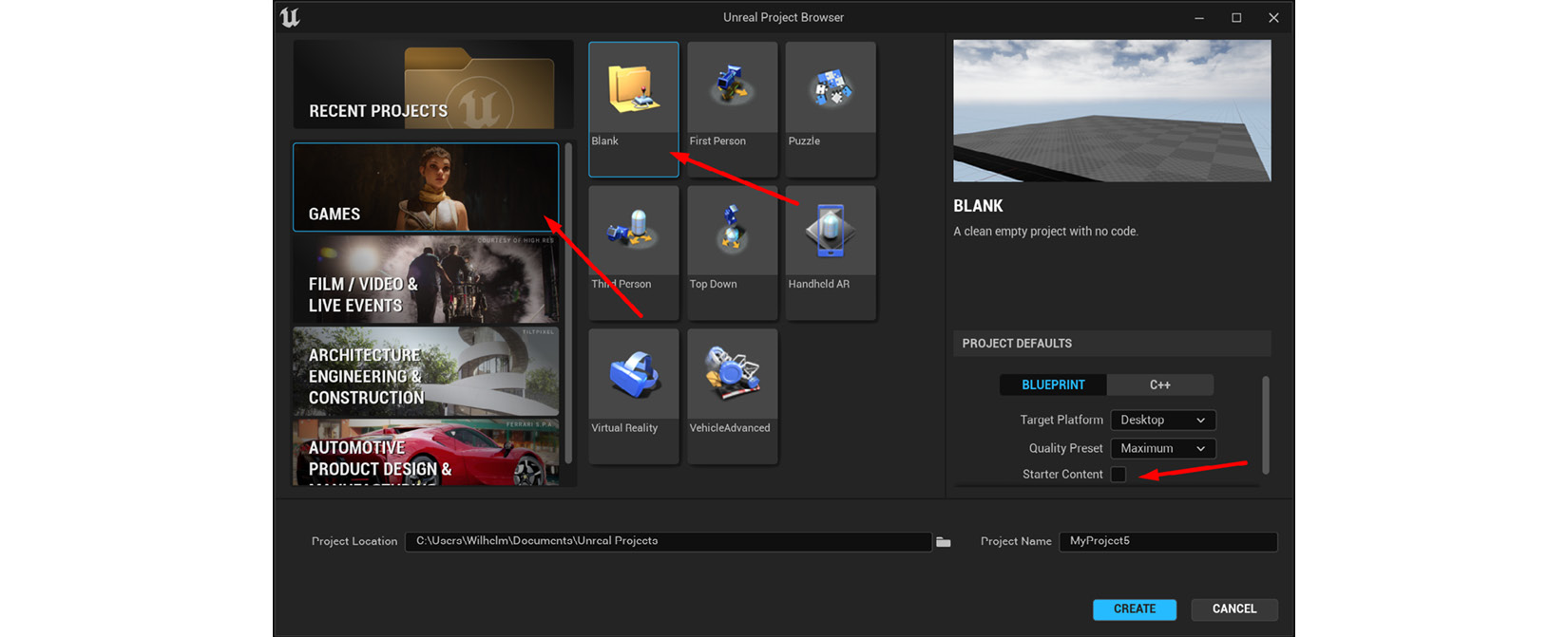
Figure 14.1 – Creating a blank UE project
- Once loaded, select Edit | Plugins, as shown in Figure 14.2:
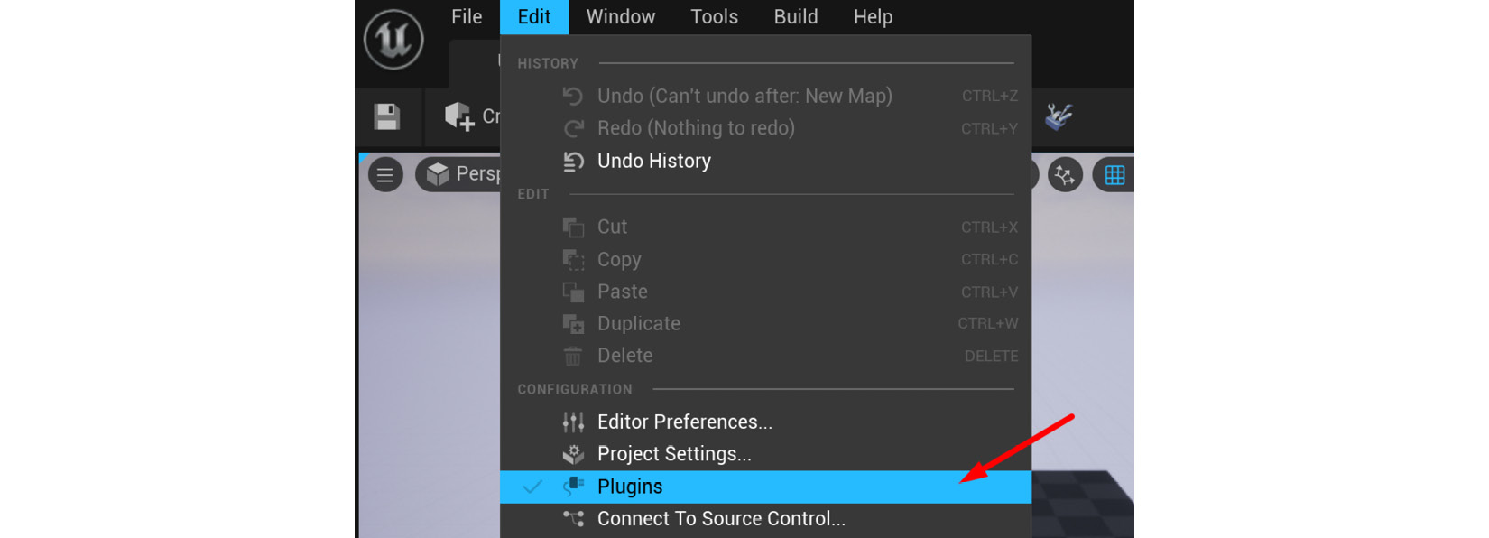
Figure 14.2 – Opening the Plugins menu
- In the Plugins menu, search for control, click the Enabled checkbox, and then click the Restart Now button to restart UE with the Control Rig tools set to Enabled, as shown in Figure 14.3:
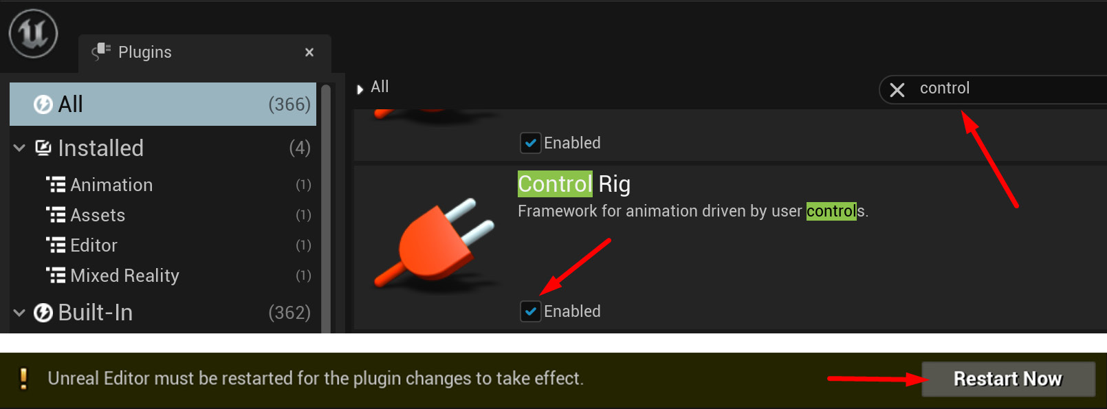
Figure 14.3 – Enabling the Control Rig plugin and restarting UE
Once UE has restarted, we will have loaded the Control Rig tools and they will be ready to use. Next, let's get our Alien Plant model into UE too.
Getting the Alien Plant and its skeleton into UE
The following is the basic process to get a skinned model FBX file into UE. We need to do this before we can work with it in UE. Once you know this process, you can import any skinned mesh into UE and then use it in your scenes or games inside UE. But first, we need to export the FBX file from Blender.
Important Note
Control Rig is much more sensitive to correct scale and orientation than just normally importing a model into UE. As a general rule, we want the root bone of our skeleton to be positioned at 0, 0, 0 if we can and the scale to be 1, 1, 1. This will make it much easier to work with and create a Control Rig for our skeleton.
Different software packages can differ in the way they handle scale and units. In the previous chapters, you should have set up Blender to have a Unit Scale setting of 0.01 while set to Meters. With these settings in Blender, exporting FBX files from Blender and importing them into UE should give better results in older versions of Blender. In newer versions of Blender, this issue might be resolved, and you can have the default Unit Scale setting of 1.0 while set to Meters.
Exporting the Alien Plant from Blender
In order to import a skinned FBX file of our Alien Plant into UE, we first need to create an FBX file of this model. Here's how you create or export a skinned FBX model from Blender to be used in UE:
- Open Blender and then the previously saved Skinned Alien Plant from Chapter 11, Alien Plant Joint Setup in Blender. You can also download a prepared version from here: https://github.com/PacktPublishing/Unreal-Engine-5-Character-Creation-Animation-and-Cinematics/blob/main/Chapter14/EndOffChapter12_Results_AlienPlant_Skinned.blend.
- Put the Viewport in Front Orthographic. This is just to get a reference of the orientation for the Export settings (we want our Export settings to be the same as our scene).
- In Object Mode in Blender, select the Alien Plant model and then hold down Shift and left-click to select the skeleton, so both are selected.
- In the top left of the Blender interface, click on File | Export | FBX (.fbx) to bring up the Export menu.
- Select the name and file location for your exported file and under the Export settings, we will have the following settings, as shown in Figure 14.4. Export the Alien Plant:
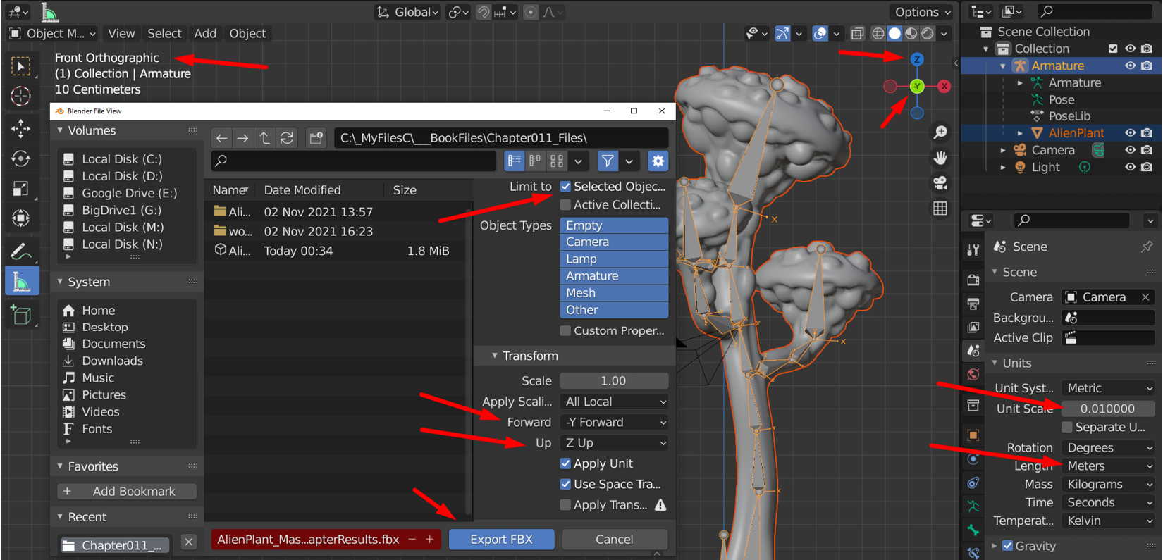
Figure 14.4 – FBX Export settings
Here's an explanation of the settings in Figure 14.4:
- Set Limit to Selected Objects in the export menu settings to only export selected objects.
- In the Front Orthographic view, you can see that -Y Forward is set. If you look at the Viewport Orientation Gizmo at the top right, you can also see that Z is set to Up. Match the Forward and Up settings in the export menu to be the same.
- Double-check that you've set Unit Scale to 0.01 and Length to Meters.
Additional Note
At the time of writing, the unit scaling issue between Blender and UE seems to mainly be a problem in older versions of Blender and how it exports scale units to UE. Some export tests I've done seem to suggest that from Blender version 3.1.2, the scale unit issue also works if Unit Scale is set to 1.0 and Meters. Regardless, the Unit Scale setting of 0.01 and Meters will work in any current version, so it is still the safest to use.
If your Blender scene's Unit Scale is not set to 0.01 and Meters on older versions of Blender, you may need to convert it. This can be fixed in the following way. A detailed description of this fix is beyond the scope of this book, but here's a brief description of the process:
- Create a new Blender scene. Set the scene scale's Unit Scale to 0.01 and Meters.
- Append the wrongly scaled model with its skeleton to this scene.
- Scale the models and skeleton if Scale is incorrect (checking the model with the Measuring tool). Normally, they will be 100 times smaller or larger. Once correctly scaled, select the Root Armature node and Object/Apply/All Transforms so the native scale is reset to 1, 1, 1.
- Do the same for the 3D model. Now, it should be ready to export to UE at the right scaling units.
Now we have a ready-to-use FBX file of our Alien Plant. Let's import it into UE.
Importing the Alien Plant into UE
Back in UE, do the following to import the Alien Plant FBX file:
- Open Content Drawer at the bottom of the interface and click on Import, as shown in Figure 14.5:
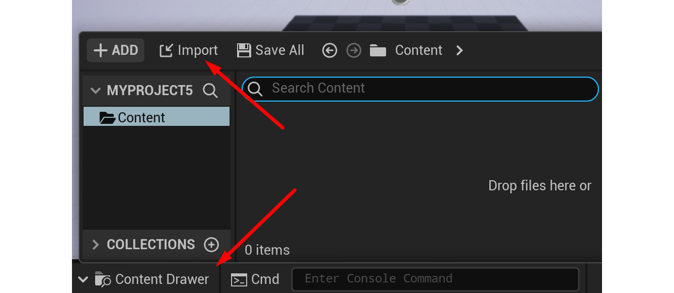
Figure 14.5 – FBX import
- In the following menu, navigate to the Alien Plant FBX file and select Open. Alternatively, download an already exported version from here: https://github.com/PacktPublishing/Unreal-Engine-5-Character-Creation-Animation-and-Cinematics/blob/main/Chapter14/EndOffChapter12_Results_AlienPlant_Skinned.fbx.
- The FBX Import Settings window will open. For the Alien Plant, we have no animation, so you can uncheck Import Animation.
- There are three additional settings that help this file import correctly – Convert Scene, Force Front XAxis, and Convert Scene Units. Check all these options, as shown in Figure 14.6. The Force Front XAxis option can be unchecked for some files to import the correct orientation. It depends on many factors:
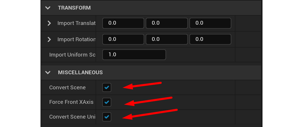
Figure 14.6 – FBX Import settings
- Click Import All. You might see a warning in a log window about no vertex weights on bones, but you can ignore it and close the log window.
- The Alien Plant asset will now be in Content Drawer at the bottom. It is divided into MATERIAL (texture), SKELETAL MESH (skinned model), PHYSICS ASSET, and SKELETON. Double-click the SKELETON asset to see the skeleton hierarchy page, as shown in Figure 14.7:
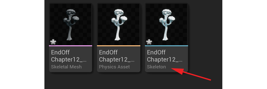
Figure 14.7 – Imported Alien Plant
- On the skeleton hierarchy page, select RootBone. Double-check that the RootBone values are 0.0, 0.0, 0.0 for Local Location and Local Rotation. Scale should be 1.0, 1.0, 1.0. Of these, it is most important to set Local Rotation and Scale to be 0.0, 0.0, 0.0 and 1.0, 1.0, 1.0, respectively, as shown in Figure 14.8:
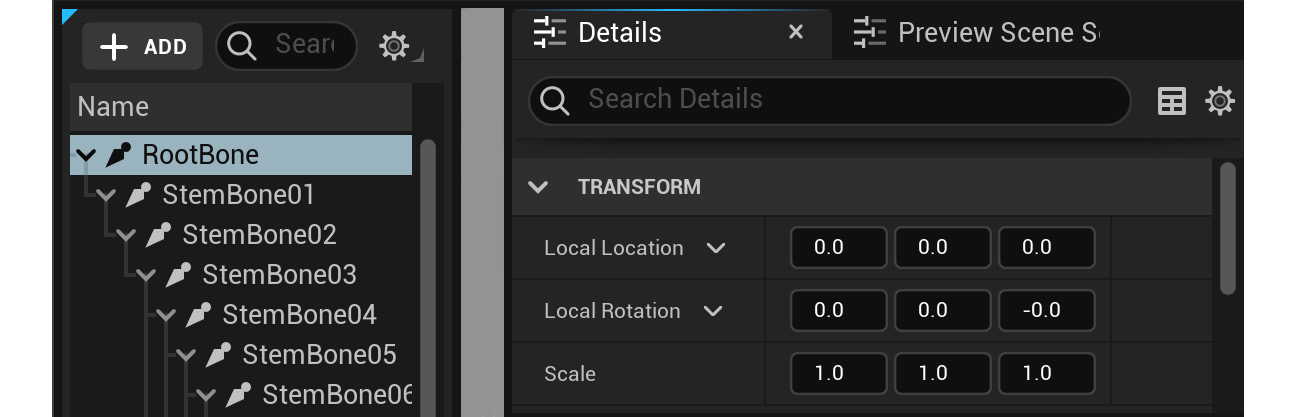
Figure 14.8 – Imported Alien Plant check
If all of this is correct, you have successfully imported your Alien Plant. We're ready to move on to the next stage, creating the Control Rig.
Creating the Control Rig node on the Alien Plant
To create the Control Rig node on top of or linked to the Alien Plant, execute the following easy steps:
- Close the skeleton hierarchy page.
- Back in Content Drawer, right-click SKELETAL MESH. The SKELETAL MESH ACTIONS context menu will appear. Left-click and select Create | Create Control Rig, as shown in Figure 14.9:

Figure 14.9 – Create Control Rig
- Double-click the new CONTROL RIG asset to open the Control Rig Editor window, as shown in Figure 14.10:
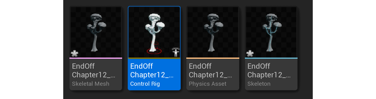
Figure 14.10 – Created Control Rig
We have now learned how to create a Control Rig node on top of our Alien Plant skeleton. Now, let's explore the main Control Rig Editor interface.
Understanding the Control Rig Editor interface layout
Let's have a look at the Control Rig Editor interface so you can navigate your way around it while working your way through this section.
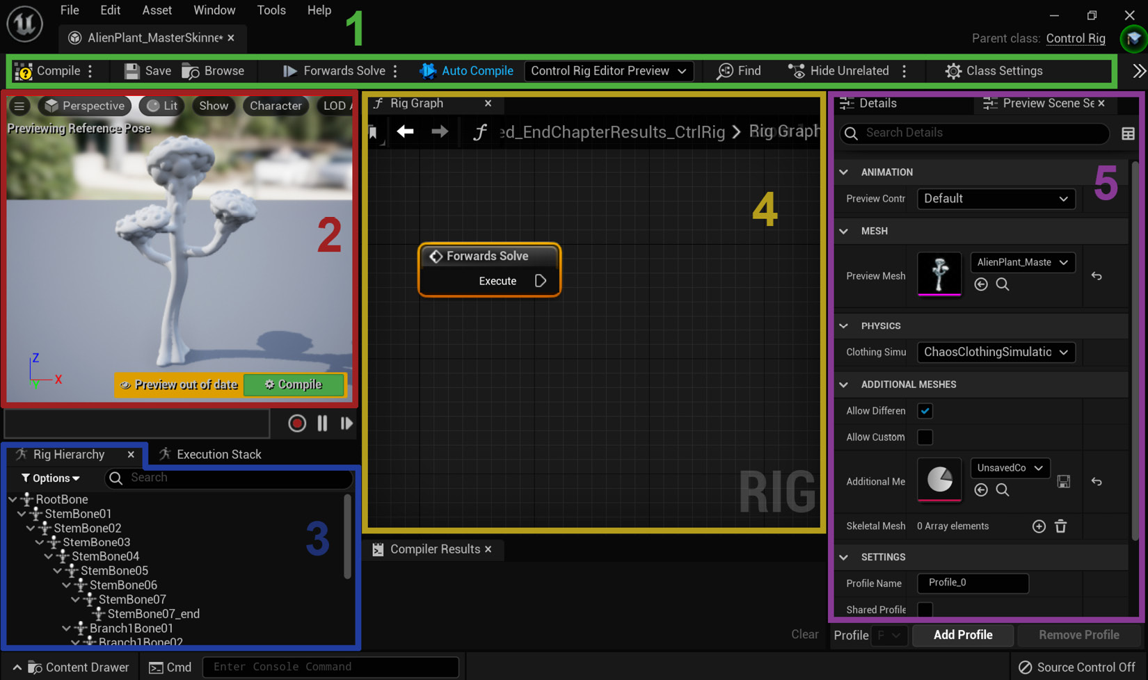
Figure 14.11 – Control Rig interface
This is just a basic layout of the Control Rig Editor interface as a general reference for what we will need in this book, as shown in Figure 14.11:
- Toolbar: This is where the basic tools are.
- Viewport: This is where you navigate the 3D scene.
- Rig Hierarchy: This is where we will see our skeleton and rig hierarchy.
- Rig Graph: This is where UE will enable us to visually add rigging elements and tools to our rig to modify its behavior.
- Details and Preview Scene Settings: This is where we can access more detailed settings of the selected object, plus set up our preview display setting.
When you first open the Control Rig interface, your Alien Plant might not display in the viewport. To fix this, in Preview Scene Settings, under Preview Mesh, select your Alien Plant Skeletal Mesh under the dropdown, as shown in Figure 14.12:
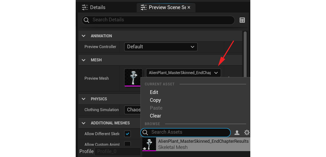
Figure 14.12 – Selecting the Skeletal Mesh
We enabled the Control Rig plugin, imported our Alien Plant, and created a Control Rig node. We are now all set up to start creating controllers for our skeleton.
Creating basic Control Rig controllers
The Alien Plant only needs a very simple forward kinematics (FK) rig setup. This sounds very complicated but FK is just basically the same parent/child setup we did with the skeleton itself. The child bone follows the parent all the way down the chain. Our FK animation rig controllers will behave in the same way.
Note
In animation, there are two main ways to control a joint: FK and inverse kinematics (IK). We will cover FK in this chapter and IK in Chapter 15, Creating a Control Rig with Basic IK Controls for the Robot in UE5.
Let's create our controllers. First, we'll create a few simple control shapes.
Creating two simple control shapes
We'll start in a very simple way and create two control shapes that will control our skeleton bones. Control shapes are the things we select in the 3D Viewport to move our character in the scene:
- Right-click on an empty space in the Rig Hierarchy panel and select New | New Control. A new controller will appear at the bottom, as shown in Figure 14.13:
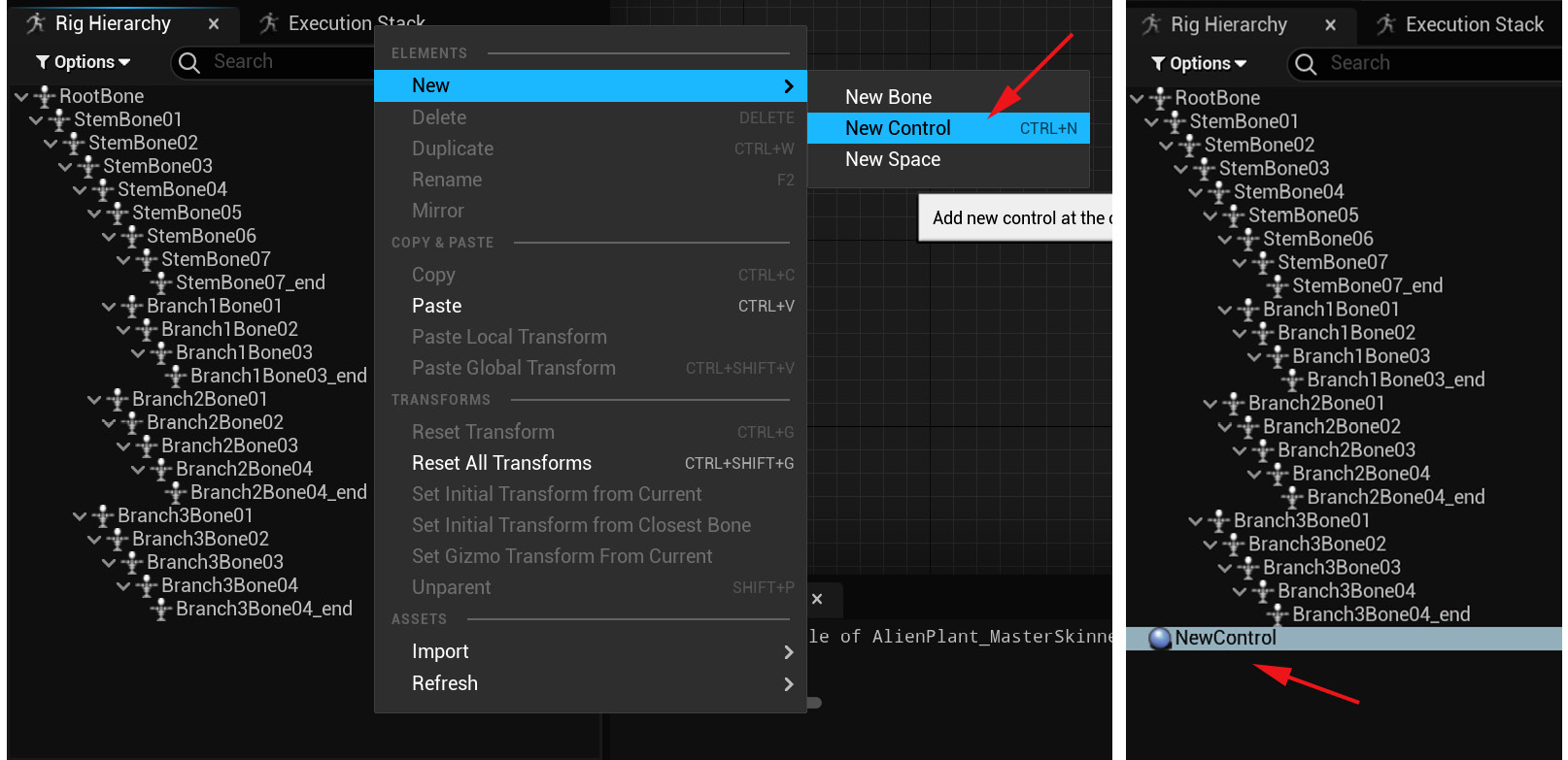
Figure 14.13 – Creating a new controller
- With the new controller still selected, on the Details panel, under Shape Properties, from the Shape dropdown, select Circle_Think. Set Shape Transform's Scale setting to 10.0 for all the axes, as shown in Figure 14.14.
This is where you can set and edit how your controller looks purely visually. There are many options here, but for our Alien Plant, the circle-shaped controllers are one of the best options. As a rule of thumb, choose controller shapes that will make it visually easier to see what you're doing while animating.
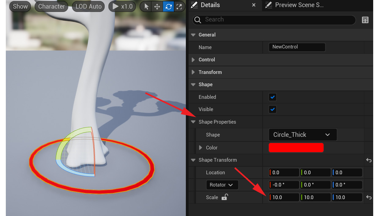
Figure 14.14 – New controller shape
- Rename NewControl by double-clicking on it in the Rig Hierarchy panel, typing Root, and pressing Enter, as shown in Figure 14.15:

Figure 14.15 – Renaming a controller
- Right-click on the newly renamed Root controller and a dialog will appear. Select Duplicate. This will make a copy of the controller. Rename it to Stem01 using the same method as in step 3, as shown in Figure 14.16:
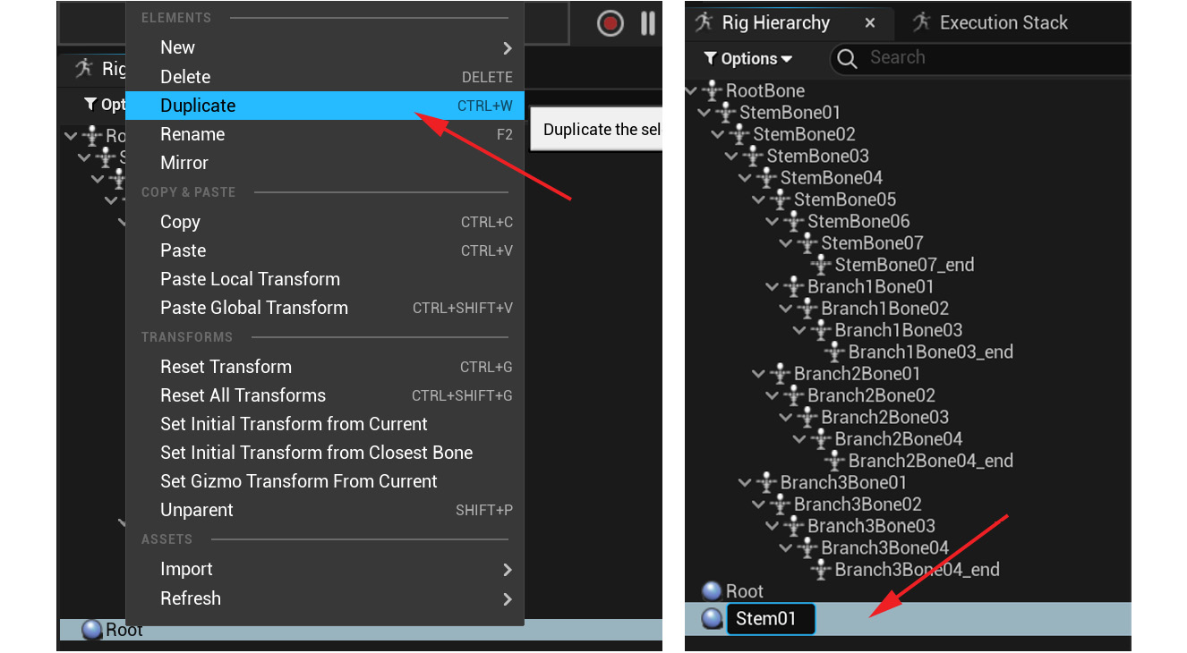
Figure 14.16 – Duplicating and renaming a controller
- With the Stem01 controller selected, change the X, Y, and Z scale to 5 instead of 10. You can now see the smaller controller, as shown in Figure 14.17:
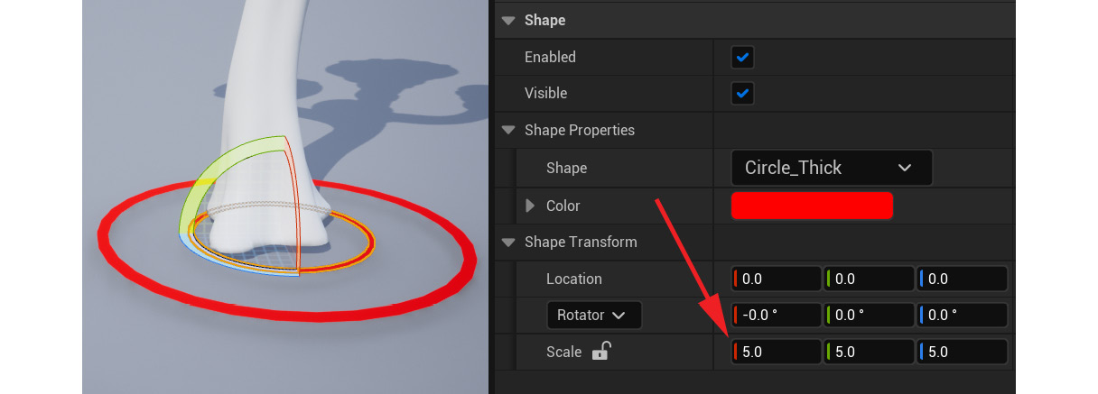
Figure 14.17 – Scaling a new controller
We have now created the two main controller shapes we need.
The bigger Root controller will be used to move our entire rigged object around. The smaller controller will be further duplicated and used as child controllers around the stem and branches of our Alien Plant.
Next, let's work out what controllers we need in this animation rig setup.
Deciding on the controllers we need
In order to decide what controllers we need, we need to work out what skeleton bone positions we want to be able to bend and deform on our plant.
Our Alien Plant has four main elements – the Main stem, Branch 1, Branch 2, and Branch 3. We want both the Main stem and the branches to be able to deform where we have our main joints.
Let's start by eliminating joints we do not need controllers for. The first bones we can eliminate, in this case, are the _end joints. They simply mark the end of the last joints in the branches and the Main stem.
In this case, on our Alien Plant skeleton, we don't need controllers for the first joint of each branch. They share the position with their Main stem parent joints. Two controllers in the same position, in this case, won't be needed. There are, however, some cases where you would want that. This needs to be considered on a case-by-case basis, based on your specific skeleton and how it needs to animate.
After eliminating unnecessary joints that we do not need controllers for, that leaves us with the joints where we do need controllers to move the joints.
In Figure 14.18, I selected these joints in the Rig Hierarchy panel to make them display in the viewport and marked their positions. In the Rig Hierarchy panel, I also marked the joints we don't need controllers for.
In conclusion, for this Alien Plant animation rig, we need the following:
- Main Root controller
- 7x Main Stem controllers
- 2x Branch 1 controllers
- 3x Branch 2 controllers
- 3x Branch 3 controllers
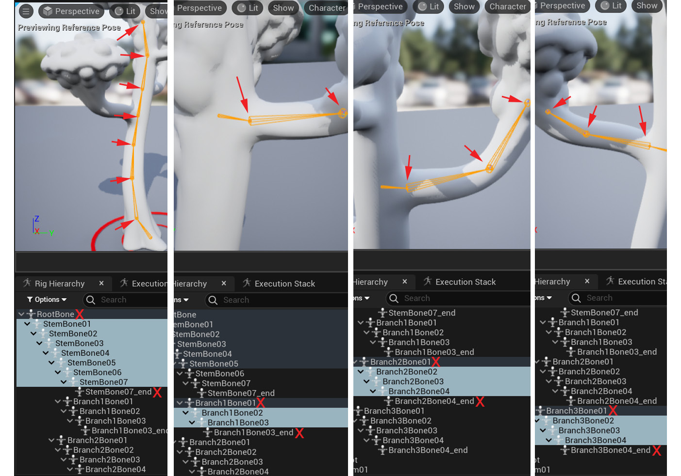
Figure 14.18 – Bones that need controllers
We have now worked out the number of controllers we need for this Alien Plant. Next, let's create them.
Creating all the controllers
In order to create our Main stem and branch controllers quickly, we're going to use the smaller controller, called Stem01:
- Right-click on Stem01 in the Rig Hierarchy panel and in the dialog, select Duplicate, as shown in Figure 14.16. You can also use Ctrl + D as a shortcut to duplicate. This will create another controller of the same size.
- Repeat the previous duplication step until you have 15 controllers that are the same (7x Main Stem controllers + 2x Branch 1 controllers + 3x Branch 2 controllers + 3x Branch 3 controllers = 15 controllers).
- Rename those controllers to correspond to the bones/joints you want to control. Try to match the names of the controllers closely (but not exactly, so you don't have duplicate names) with the actual bone names so it is easier to link them up correctly later, as shown in Figure 14.19.
To the left in Figure 14.19 are the duplicated controllers, while to the right are the bone names. In the center are the final controller names after the rename:
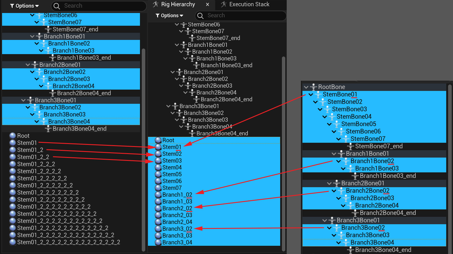
Figure 14.19 – Controller names
We have now created all the controllers we need. Next, we want to organize them in a hierarchy that makes the Alien Plant easy to animate.
Organizing the controllers in a hierarchy
As mentioned earlier in the chapter, we want to create a simple FK setup for our Alien Plant. This is remarkably similar to our current skeleton hierarchy.
Note
You might ask: Why don't we just animate the bones directly, instead of going through all this trouble of creating a Control Rig animation setup? The answer is you could, but it is not the best way to work. Having an animation rig makes everything a bit easier. When we get to IK in Chapter 15, Creating a Control Rig with Basic IK Control for the Robot in UE5, you absolutely need a Control Rig to make it work. Most character animation rigs have a combination of FK and IK in the same rig.
In our Alien Plant skeleton, we have four parts: the Main stem and the three branches. Each of these is just a simple parent/child chain, so let's create these simple hierarchies.
It is very simple to create a hierarchy in the Control Rig interface:
- In the Rig Hierarchy panel, left-click to select and hold the mouse button on the child and drag it on top of the parent. In this case, left-click to select and hold the mouse button on the child, Stem02, and drag it on top of the parent, Stem01, as shown in Figure 14.20:
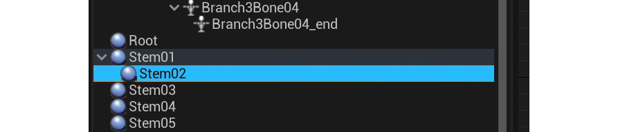
Figure 14.20 – Controller hierarchy
- Repeat this process until the Main stem and the three branches are organized in separate parent/child chains, as shown in Figure 14.21:
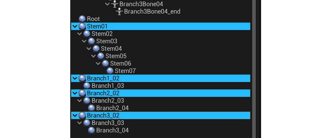
Figure 14.21 – Controller hierarchy
Finally, we need to complete the hierarchy. We need to make the branch hierarchy parent the children of the appropriate bones on the Main stem.
- In this case, the Branch1 chain should be the child of Stem06. Left-click to select, then hold the mouse button on the child, Branch1_02, and drag it on top of the parent, Stem06.
- The Branch2 chain should be the child of Stem05. Left-click to select, then hold the mouse button on the child, Branch2_02, and drag it on top of the parent, Stem05.
- The Branch3 chain should be the child of Stem04. Left-click to select, then hold the mouse button on the child, Branch3_02, and drag it on top of the parent, Stem04.
- Finally, the Stem01 chain should be the child of Root. Left-click to select, then hold the mouse button on the child, Stem01, and drag it on top of the parent, Root.
The final result should look like Figure 14.22:
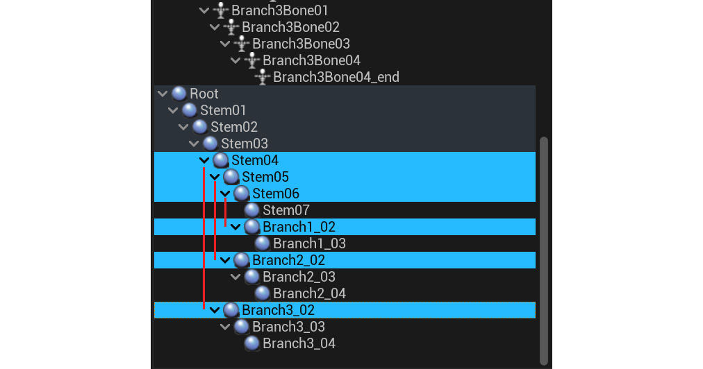
Figure 14.22 – Controller hierarchy
We have now created a hierarchy very similar to our skeleton, but since we need fewer controllers than joints, it is slightly different. Now, we need to position the controllers on the joints.
Positioning the controllers on the joints
At the moment, this setup doesn't look like much since all the controllers are on top of each other at the origin of the scene. The reason we do the hierarchy first is that if we did the positions first, the relative offset of the controllers as children would have to be constantly readjusted as we changed the hierarchy. With our hierarchy already correct, we only need to position them once.
Our bigger Root controller will stay at the origin of the scene.
There is a simple method to position the other controllers exactly on the joints. Right-click to select the bone/joint. In the dialog that appears, select Copy. Then, right-click to select the corresponding controller, and in the dialog that appears, select Paste Global Transform, as shown in Figure 14.23:
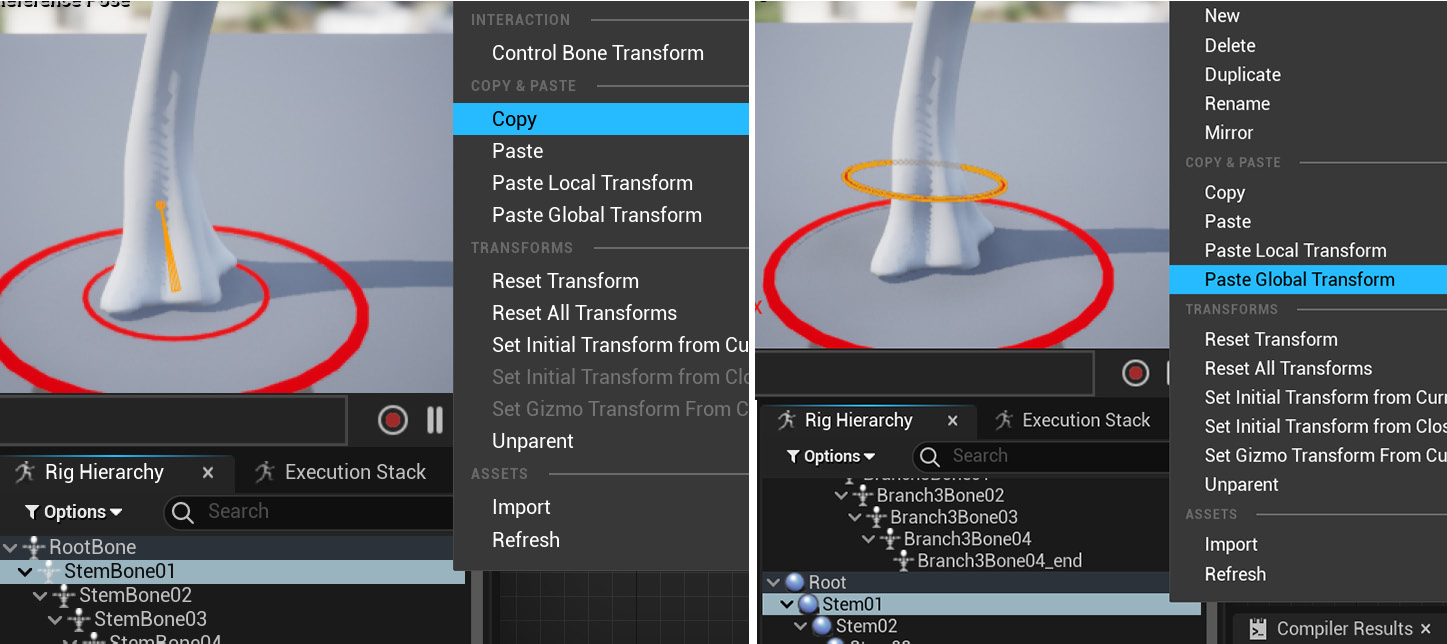
Figure 14.23 – Controller position
To make this new position on the controller permanent as far as the rig is concerned, right-click to select the controller again and then select Set Offset Transform from Current, as shown in Figure 14.24:
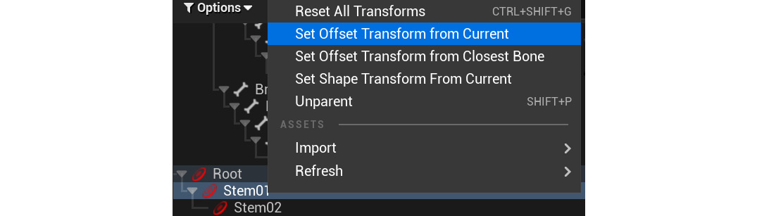
Figure 14.24 – Setting the controller position
Now, let's do this for StemBone01 first:
- Start with the StemBone01 bone and paste the position to the Stem01 controller, then right-click to select the controller again and then select Set Offset Transform From Current, then repeat these steps, working your way down the hierarchy from parent to child in the following order: Stem01, then Stem02, then Stem03 to the end of the stem joint chain.
- Once the Main stem is done, repeat this process for the branches, also working down the hierarchy, like with the Main stem.
- The final result should look like Figure 14.25. Additionally, you can scale the controllers further by changing the Shape scale values, as shown in Figure 14.17, so visually, it's easier to make sense of it:
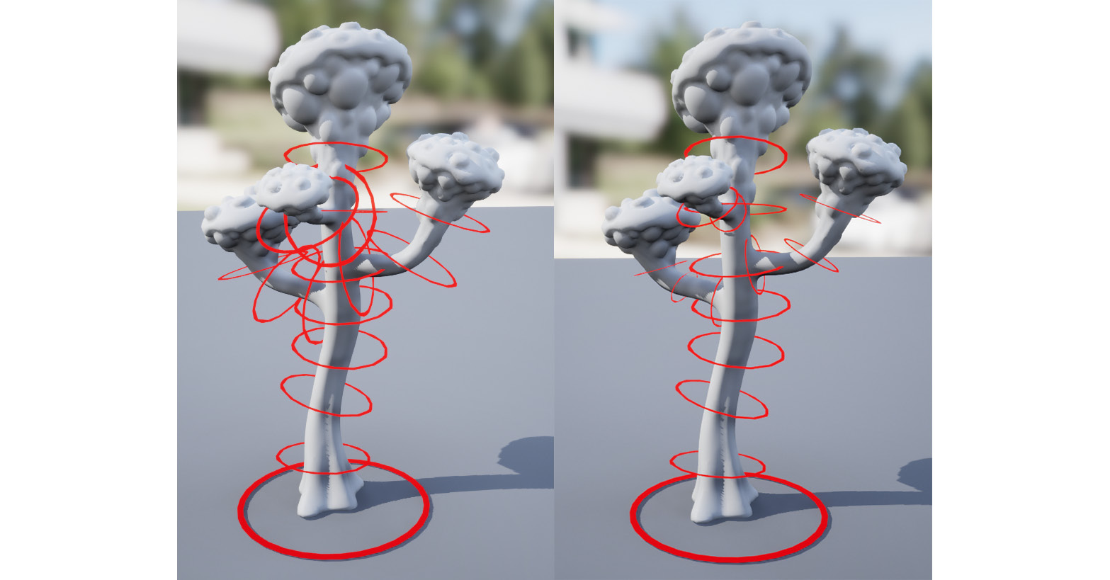
Figure 14.25 – Controller position results
We've now created all controllers and positioned them so they line up exactly to the bones they will control. Next, we'll get the controllers to control the bones in our skeleton.
Controlling the Alien Plant skeleton with the controllers
The final step in creating the Control Rig for our Alien Plant is to get the controllers to drive/control the skeleton. The Control Rig system can be used to create very complicated rigs that are beyond the scope of this book. The Control Rig system uses a series of nodes that can be linked together in a visual way to drive the behavior of our Animation rig.
For a simple FK, we just need a few basic nodes in our Rig Graph panel, as follows:
- Forwards Solve: This node simply starts the flow of the rig node logic and is at the start of any Control Rig we build.
- Set Transform - Bone: This is typically used to "set" or receive the transform values from the controller and apply them to the bone.
- Get Transform - Control: This is typically used to "get" the transform values from the controller and feed them to the bone.
If this sounds complicated, don't worry. It is simpler in practice than it sounds.
Practical setup for three basic nodes
Let's create a setup to drive RootBone with the Root controller:
- In the Rig Hierarchy panel, left-click to select and hold the mouse button and drag the RootBone bone into the Rig Graph panel.
- Let go of the mouse button and a dialog will appear. Select Set Bone, as shown in Figure 14.26:
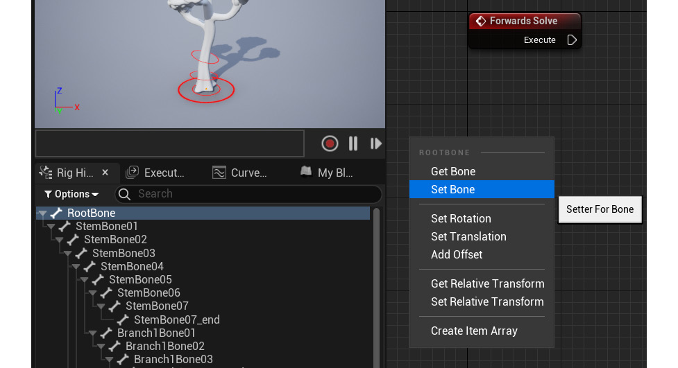
Figure 14.26 – Set Bone
A Set Transform - Bone node box will be created. Note that under Type, it's Bone, and under Name, RootBone has been automatically set, as shown in Figure 14.27.
- On the Forward Solve node box, there is an Execute socket. Left-click on the arrow socket next to Execute, hold the mouse button, and drag to create a connecting line. Drag this line to the Execute socket on the Set Transform - Bone node box and release the mouse button to create the connection, as shown in Figure 14.27:
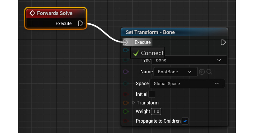
Figure 14.27 – Set Transform results
You can select the node boxes and move them around. You can use the mouse wheel to zoom in and out, and the right mouse button to pan around the Rig Graph panel.
- In the Rig Hierarchy panel, left-click to select and drag the Root controller into the Rig Graph panel. Let go of the mouse button and a dialog will appear; select Get Control, as shown in Figure 14.28:
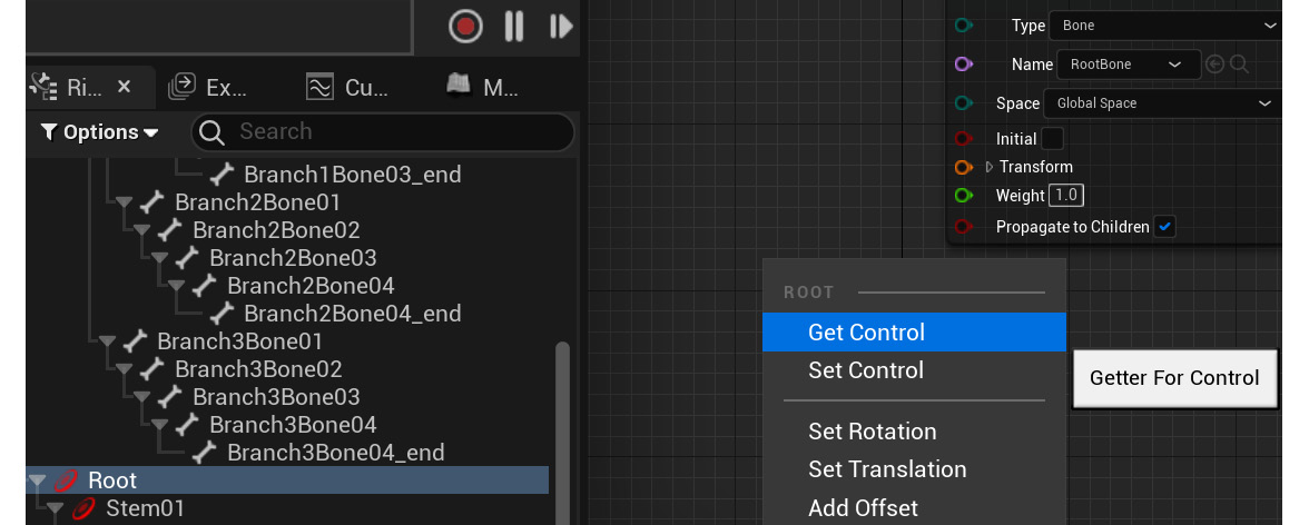
Figure 14.28 – Get Control
This will create a Get Transform - Control node box, as shown in Figure 14.29.
- On the Get Transform - Control node box, at the bottom is an orange Transform socket. Left-click on this socket, hold the mouse button, and drag to create a connecting line. Drag this line to the Transform socket on the Set Transform - Bone node box and release the mouse button to create the connection, as shown in Figure 14.29:
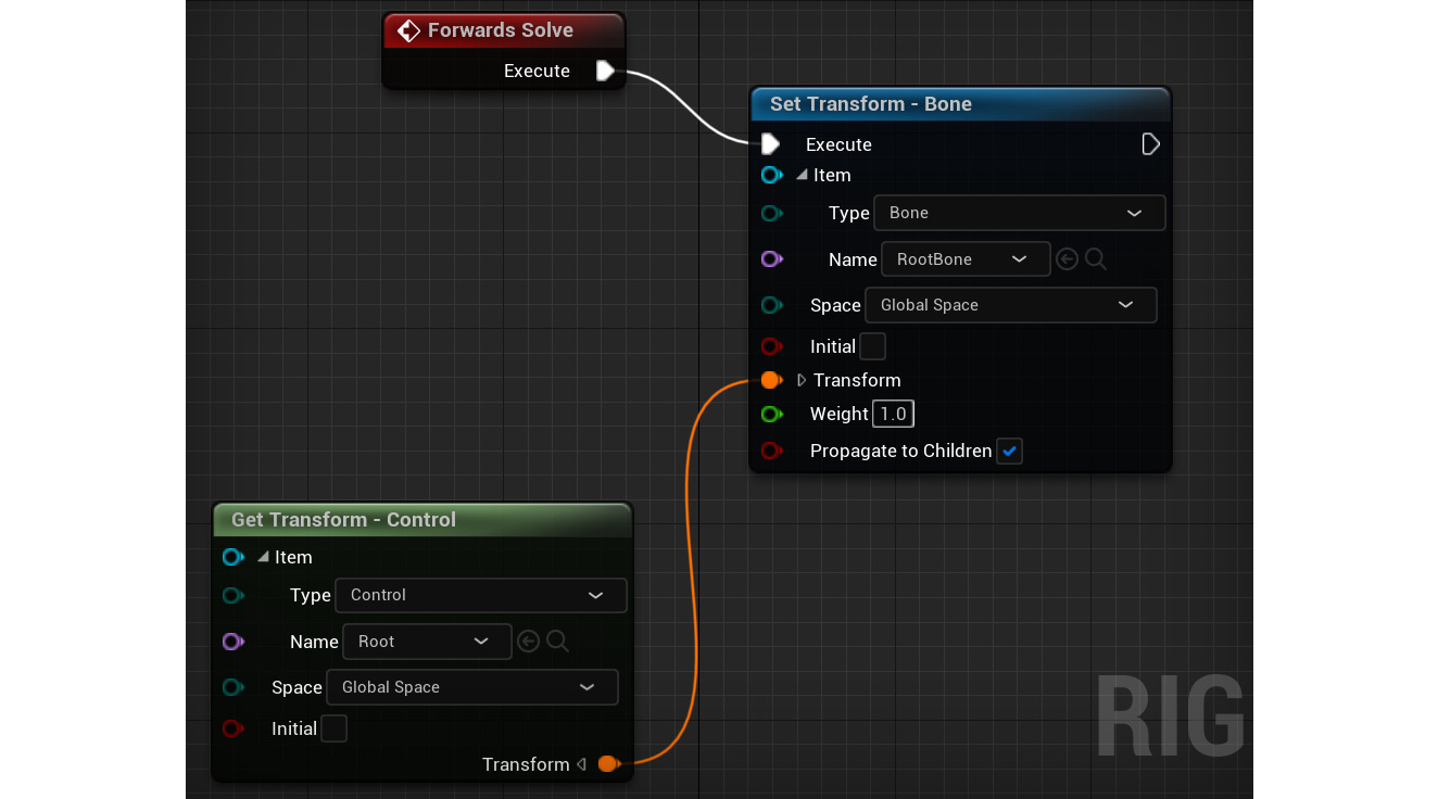
Figure 14.29 – Transform connection
The Root controller now feeds its transform values into RootBone and drives/controls it.
Note
If you make a mistake, you can use Alt + left-click on the connection line or socket to delete the connection.
- If not checked already, check the Propagate to Children checkbox and the resulting setup should look as in Figure 14.30:
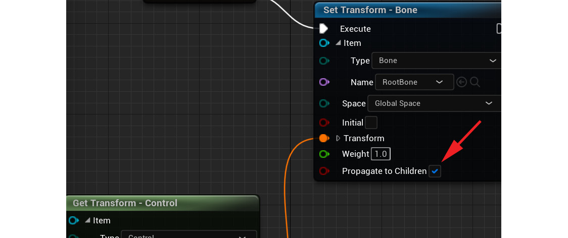
Figure 14.30 – Propagate to Children
- You can now test this setup to make sure it's working correctly by selecting the Root controller, then moving it in the viewport. When you move the Root controller, the whole plant should follow as a result, as shown in Figure 14.31:
Important Note
Be careful not to use undo (Ctrl + Z) after you move or rotate controllers in the viewport in the Control Rig interface. It will undo the last things you did on the rig setup and not undo the translation on the rig itself in the viewport. Instead of undo, click Compile at the top left to return your rig to its original pose and translations, as shown in Figure 14.31.
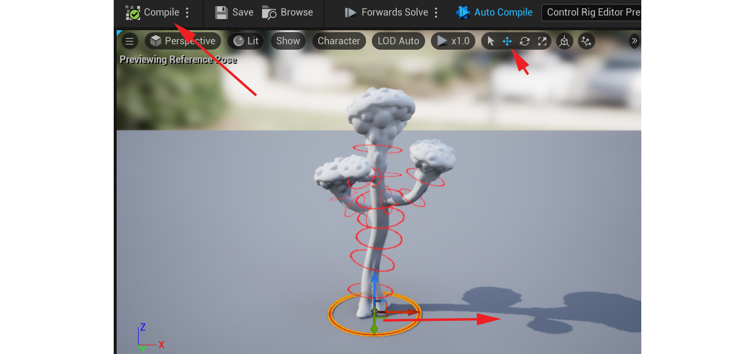
Figure 14.31 – Test root setup
We have now set up one controller driving one bone. Now it's time to hook up the rest.
Completing the animation rig
To set up the rest of the animation Control Rig, we follow exactly the same process as the Root controller setup. Here's a recap:
- Left-click and drag Bone into the Rig Graph panel and select Set Bone.
- Reposition the resulting Set Transform - Bone node box.
- Create a new link from Execute on the previous Set Transform - Bone node box to Execute on the new Set Transform - Bone node box.
- Left-click and drag the corresponding controller that will drive that joint into the Rig Graph panel and select Get Control. A new Get Transform - Control node will be created.
- Link the Transform socket from the new Get Transform - Control node box to the corresponding Set Transform - Bone node box's Transform socket.
- Check Propagate to Children if needed.
- Repeat this process until you've done all your controllers. The bones without a corresponding controller can be ignored.
After we complete three of the controllers, it should look as in Figure 14.32. This flow continues until all controllers are connected:
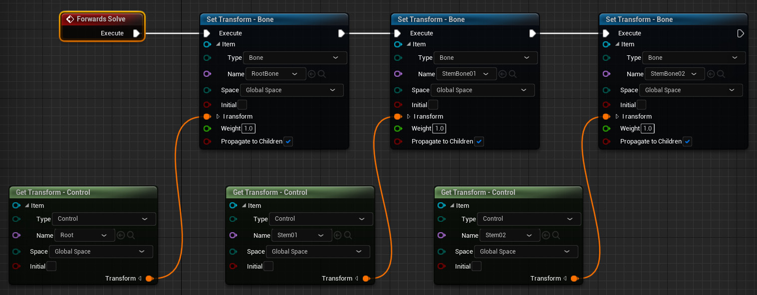
Figure 14.32 – Three controllers set up
After we have completed all of the controllers, it should look as in Figure 14.33:
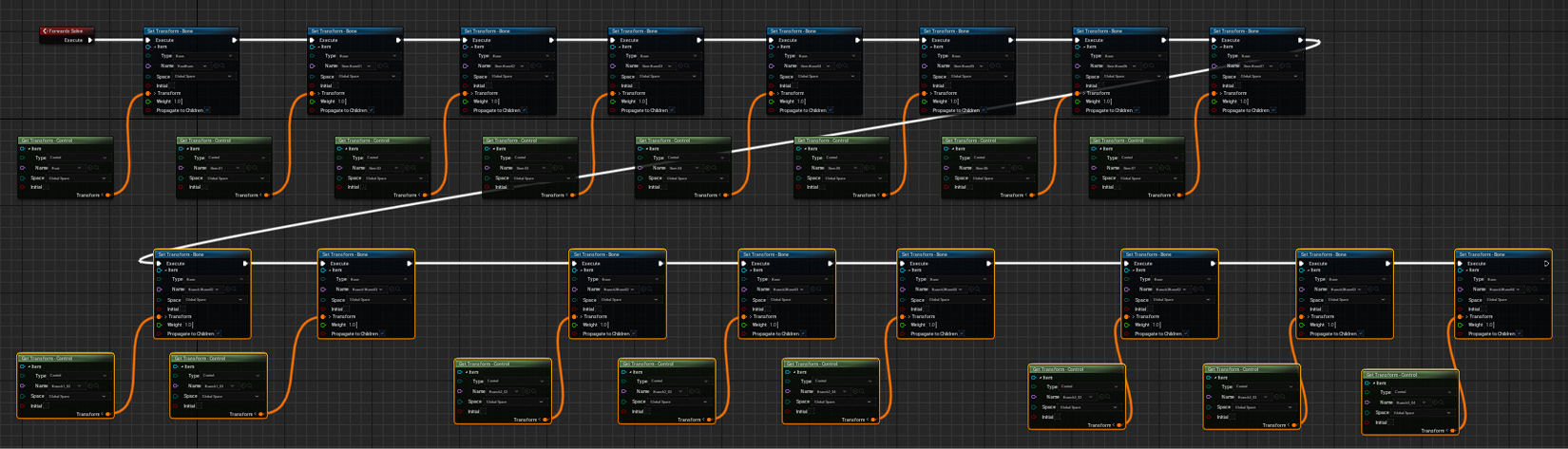
Figure 14.33 – All controllers set up
It looks complicated, but it is just the same two basic nodes repeating to cover all our controllers, linked together by Forward Solve/Execute. In Figure 14.33, the connected nodes are organized in two horizontal tiers to fit easier on the screen, but it doesn't affect the rig behavior.
You can now test your Control Rig setup by rotating your controllers and making sure the Alien Plant and its skeleton are following and deforming with the controllers, as shown in Figure 14.34. Remember to use Compile instead of Undo during the testing. If everything is fine, you can save your UE5 project in a safe place for later use:
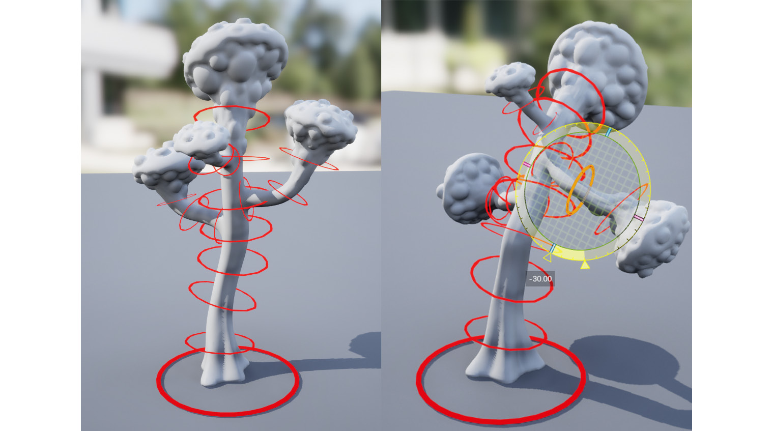
Figure 14.34 – Testing rotations
We provide the completed Control Rig in the final project file, which can be downloaded here with installation instructions: https://github.com/PacktPublishing/Unreal-Engine-5-Character-Creation-Animation-and-Cinematics/tree/main/FullFinalUE5Project.
The example Control Rig is under Content/AlienPlantControlRig.
We now have a completed Control Rig for our Alien Plant.
Summary
In this chapter, we learned how to correctly export our Alien Plant from Blender and import it into UE. We learned how to activate the Control Rig plugin and navigate its basic interface. Finally, we built a basic FK rig with the Control Rig system. With this knowledge, you can now build FK animation rigs in a UE5 Control Rig. This means you can build FK animation rigs for all kinds of different animated objects and characters for your scenes.
In the next chapter, we will build a Control Rig for our robot that will include IK.