
7. Connecting Shapes
In This Chapter
• How do I connect all those great ideas?
• Can I glue safely without getting any on me?
• How will connectors and glue add meaning to my diagram?
• How do I work with connector paths and line jumps?
• How do I add my own points using the Connection Point tool?
A big part of Visio’s power is showing how objects such as shapes interact with each other. The capability to accurately represent this relationship is crucial to an effective diagram.
You could imply relationships by the way you arrange your shapes, but Visio diagrams should be clear and easily understood without forcing viewers to guess what they are seeing. In fact, some diagrams by their very nature require the use of lines and arrows to sort out the steps that need to be followed to see a process through to its conclusion. This chapter takes a look at how connectors are used in Visio diagrams.
What Are Connectors?
Connectors are the lines and arrows that connect one shape to another. Similar to the string that threads a pearl necklace, connectors ensure that steps, thoughts, or processes are followed in the correct order.
Connectors are technically considered one-dimensional shapes. As such, they have properties that influence the relationship between your shapes. They can be simple lines slapped into a diagram, as shown in the basic org chart in Figure 7.1; however, you occasionally need to jazz up your diagrams by using connectors in a more elegant manner.
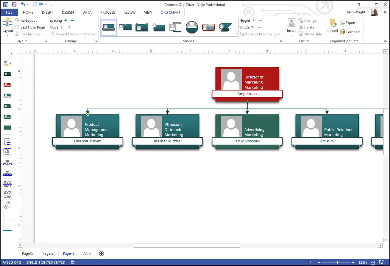
FIGURE 7.1 The connector lines connecting the components in this org chart make it easy to see who reports to whom.
How to Connect Shapes
Connectors are fairly docile and easily tamed. To understand how they work, take a look at how to connect a few steps in a basic flowchart that has been created for a new secretary. In this example, you rely on the AutoConnect feature that is often the default method used to connect shapes.
1. Start a new basic flowchart.
2. Drag a start/end shape onto the drawing and type Greet Caller into the shape.
3. Hover your pointer over the Greet Caller start shape and look for four faint arrows that point away from this shape.
4. Hover over the lower arrow. When a choice of shapes appears, select the rectangular Process shape (see Figure 7.2).
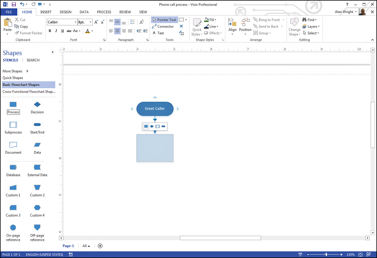
5. Check out the new process shape in place and connected by a connector that has an arrow indicating the direction of the flow in this process. Select the shape and then type How may I assist you today?
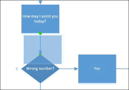
6. Repeat Steps 3-5 to create a series of autoconnected shapes until your flowchart resembles the one shown in Figure 7.3. Add a diamond shaped decision shape along with an end to the process in the case of a wrong number.
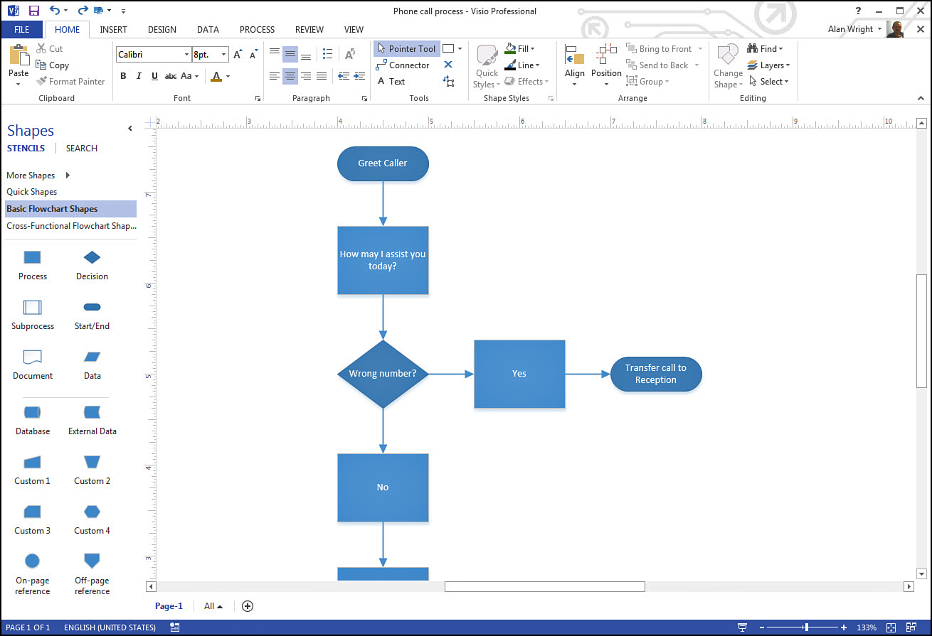
FIGURE 7.3 A quick flowchart with some connector lines slapped in takes just a few seconds to create.
7. Select and drag your second step in the flowchart and move it to a different part of the drawing page. Notice that the connected lines stretch and adjust to the new location (see Figure 7.4).
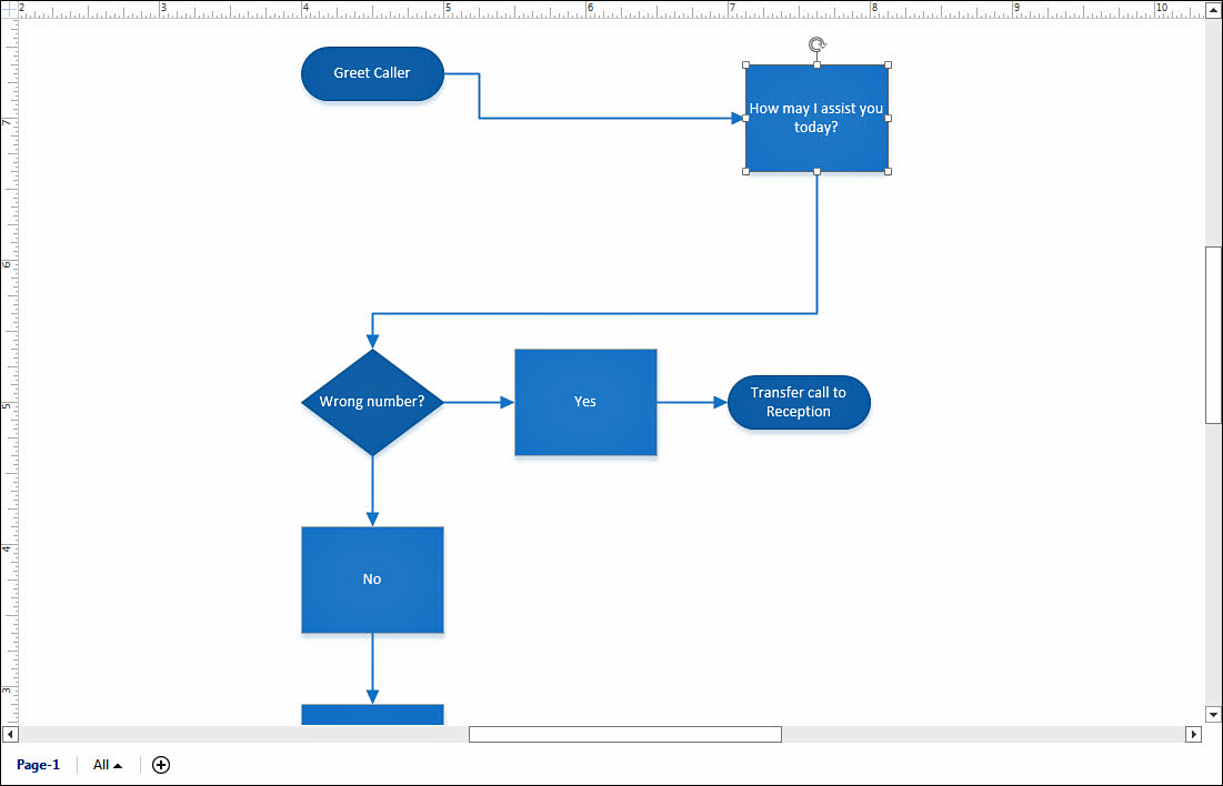
As you can see, connecting shapes is very easy using AutoConnect. The ability to move shapes and keep the connection saves you lots of time. Later, this chapter covers the glue that allows shapes to stay connected to the connector lines.
Using the Connector Tool
Despite how easy it is to use the AutoConnect feature, there may be times when you prefer or need to manually create these connections.
For one thing, it can be faster when you know what connections need to be created, and you do not want to wait for the hover-generated options to appear. Also, when a shape has another shape autoconnected, you do not have another AutoConnect option offered on that same side.
There are other times when Visio does not offer AutoConnect options. This is generally the case when working with templates that seldom use lines and arrows to connect shapes, such as the Office Layout template and the Timeline template. A layout of your conference room is not likely to need any relationships illustrated between the table and the credenza on the wall; however, suppose you need to show the cables that connect a phone on the credenza to another telephony device on the conference table, as shown in Figure 7.5.
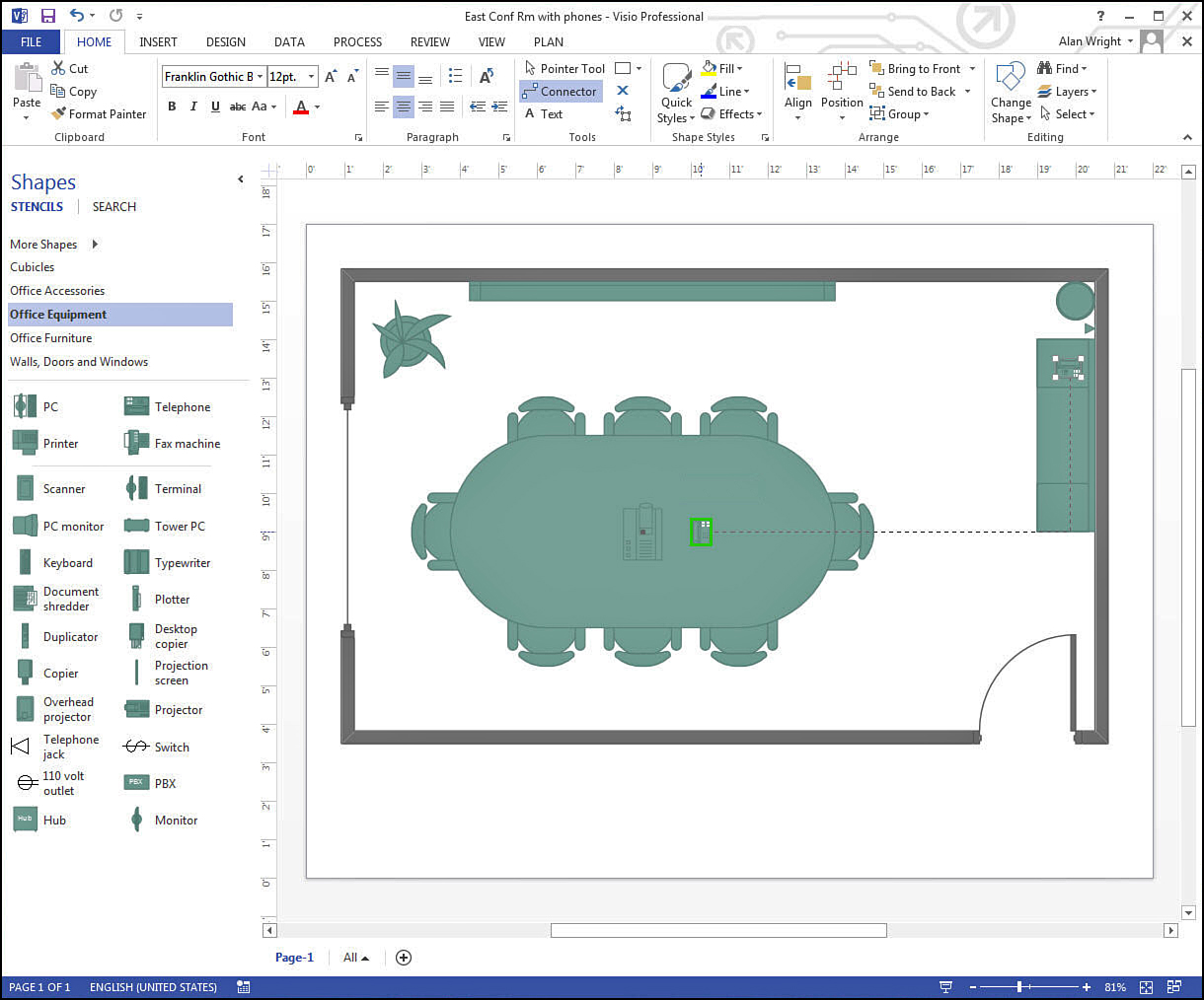
1. With your drawing window open, switch from the Pointer tool to the Connector tool (alternatively, you can also press Ctrl+3). Select the first shape; hold down the left button on your mouse and drag a connector line to the second shape to establish a connection (see Figure 7.5).
2. Repeat until all connections have been established.
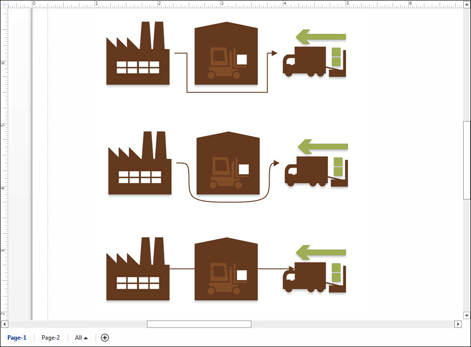
3. You may modify the properties of the connectors. In Figure 7.6 the lines are changed to a bold color to stand out, and instead of arrows they have bullet-ended lines. Also notice that one is formatted as a curved connector whereas the other is a right-angled connector.
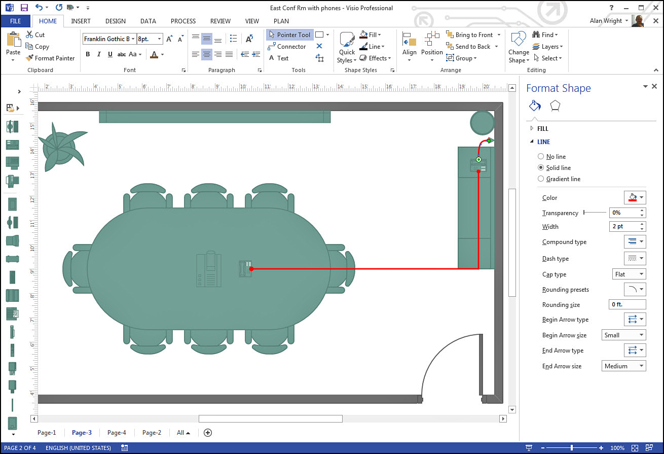
FIGURE 7.6 The Connector tool allows you to quickly create connections that can then be customized to suit your needs.
The Connector tool can also resize and move connector lines that have been placed in a drawing. As you mouse over your drawing, notice the cursor change from the default cursor to crosshairs (move) and two-sided arrows (adjust). The Pointer tool also can handle these tasks if the connector has been selected, thus saving you from unnecessarily switching tools.
Understanding Connectors
As mentioned earlier, connectors are technically one-dimensional shapes. Similar to regular shapes, they have properties that can be changed to suit your needs. For example:
• You can change the color and line weight of your connector.
• You can modify the line ends.
• You can modify the shape and position of a connector using its control handles.
• You can add text that is placed on the connector. It can be moved off the connector, but it follows the connector if the connector is moved because it is a property of the connector.
• You can copy, cut, paste, and duplicate connectors.
• You can change the style associated with a connector.
Connecting Shapes Versus Points
We have connected shapes and even moved shapes around to see how the connector behaved. The magical ability that enables the connector to follow the shape is referred to as glue.
This glue comes in two flavors. Next, you learn how and when you most often use both of them.
Using Point-to-Point Glue
Point-to-point glue, as the name implies, sticks to a specific point on a shape while Dynamic glue just connects shapes using whichever point is convenient. Point-to-point glue forms a static and permanent bond to the selected point. Most shapes have predefined points that you can choose that appear as dots around the shape when the Connector tool nears the shape. After you position the cursor over the dot, a colored box highlights the point, and you can click to apply the glue.
If the dots are not visible, it is possible that the shape does not have predefined points. Also, you may want to check to be sure that they are not disabled. Check the View tab, Visual Aids, and make sure the box is selected for Connection Points.
Point-to-point glue gives you greater control over how two shapes are linked together. You may need to exercise that capability to avoid confusing or inappropriate points from being connected in your diagram. Dynamic glue tends to combine multiple connectors to the same point when it feels the need. This may work against your diagram’s intention.
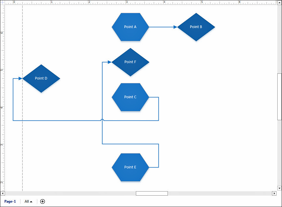
The downside of point-to-point glue is that this type of glue might make things appear more jumbled if shapes get moved around later. Consider the connector lines linking points A and B in Figure 7.7. The same points are used between points C and D, and E and F. By forcing these two points to always be used, the drawing has some issues after rearranging and could even complicate the print job as one of the connectors is forced off the page area.
Using Dynamic Glue
The purpose of dynamic glue is to maintain the relationship between the two shapes; thus, it uses whichever point seems to be better suited. Dynamic glue uses the shortest routing between two shapes that is possible unless shapes are too close together. For that reason it can result in neater and better organized diagrams.
AutoConnect creates dynamic glue bonds automatically. To create a dynamic glue connection manually with the Connector tool, you can choose to select the shape instead of a specific point.
 Tip
Tip
You can mix your glue styles when necessary. One end of the connector can be glued to a shape with dynamic glue, and the other can be glued to a specific point.
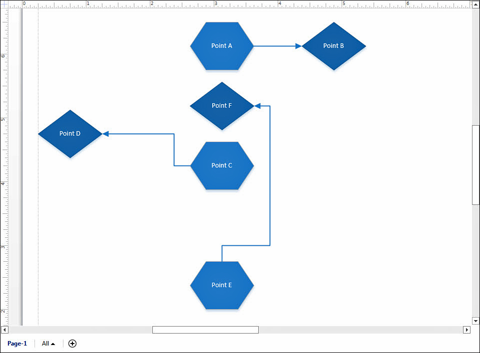
All the shapes in Figure 7.8 are connected with dynamic glue. Dynamic glue has used different points to make the connection as easy to recognize as possible under the circumstances avoiding crowding and crossed lines. Compared to the point-to–point glue used in Figure 7.7, dynamic glue has provided a simpler and cleaner diagram.
Now that you see how to use both types of glue, you might want to mix both types to suit your needs. Visio provides visual cues that appear when you have selected an end of a connector and are about to attach it to a shape. Hover for a second before releasing the mouse button and you see a confirmation of the type of glue that is about to be used. You will see the text Glue to Connection Point, and the point itself is highlighted, or it highlights the shape and the text Glue to Shape appears.
What Happens to Connections...
As a designer, you probably have felt that nagging sensation that you could break an elaborate spreadsheet or maybe lose work by accidently clicking something you shouldn’t have. Consider some situations that you might get into and see how connectors will behave...
...When I Drag a Shape?
You have seen examples of rearranging a drawing while discussing glue in Figures 7.7 and 7.8. Your connector lines stretch and reroute based on obstacles and the type of glue used. You won’t break your drawing, and you can always move your shape again and the connector knows to follow. If you decide you do not like the way a connector has routed dynamically, you can select the offending end of the connector and drag it to a different point on your shape. It is now statically glued. No worries.
...When I Split a Connector?
Have you ever forgotten a step and then had to go back later to add it into a process? It happens. In Visio you can easily insert a shape onto an existing connector. As you select a shape and drag it over the connector, both ends of the connector are highlighted, letting you know the connector is ready to accept the new shape (see Figure 7.9). You simply let go, and the shape nests itself. You are actually splitting the connector because now it becomes two separate connectors (see Figure 7.10). Again, nothing is broken here.
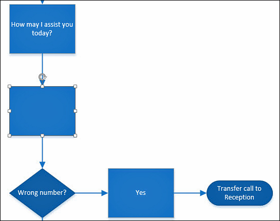
You should be aware of how the split affects your diagram. When there is enough space, the connector absorbs the new shape, and you have two shorter connectors as a result. The glue is dynamic for the new shape.
If the space is less than adequate, as was the case in Figure 7.9, you see the entire diagram shift to create the minimum space required to accept the new shape. It is incredible to see a very complicated diagram morph and shift to accommodate the addition, and as a result of this addition you may want to tweak some spacing or positioning.
Although a few templates do not have this capability enabled, for most practical scenarios wherein you might need to split connectors, the feature is ready to go.
...When I Delete a Shape?
You might be nervous about deleting a shape from your diagram when it is connected to other shapes. In Visio the effects are fairly predictable. If the shape is at the beginning or end of a process, the shape and connector are both eliminated. The exception to this behavior is in the case that the connector has text associated with it. In that case, only the shape is deleted. The connector is left hanging because Visio assumes this connector is important because you took the time to add text.
What happens to a shape that is in the middle of a process? Again, the connector is able to bridge the gap, and the flow would find itself connected to the next shape (see Figure 7.11). A word of caution, though; the connector would be unable to repair the gap if text were assigned to connectors on both sides of the shape. In that case you need to manually repair the gap afterward, or remove the text before deleting the shape.
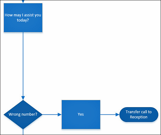
FIGURE 7.11 Deleting a shape from a flowchart does not cause major damage. In this case, the shape added to Figure 7.10 has been deleted, and the gap was absorbed by the connector.
Tip
When you have adjusted diagrams and added or removed shapes, you may find things in a bit of disarray. Rather than trying to manually repair all the chaos these changes have caused, use the Auto Align, Position, and Layout tools discussed in Chapter 6, “Manage Shapes,” for managing and arranging shapes.
Modifying Connectors
Depending on the template you use, the connectors have a default appearance and style that is appropriate to that type of template. A flowchart has connectors that help make the order of steps clear, and they tend to have rigid lines and right angles that emphasize that these are established, clear-cut policies. A diagram used for mind mapping is not rigid; instead, it uses connectors that flow and that connect shapes. Direction of flow is not indicated. You can likely think of other variations based on what you have seen.
Does this mean that you are forced to use the connectors included in the template? Of course not. Visio connectors can be modified in many ways, and you can do this on a single connector or on an entire page or document at once. Themes, discussed in Chapter 4, “Taking Control of Your Diagrams,” provide an easy way to change elements of a diagram, including the style of the connectors used.
Formatting
To manually alter the format of your connector lines on a page, you could drag and select an area that includes the connectors you want to modify and edit the line properties. In the following steps, you change the arrows used in Figure 7.11.
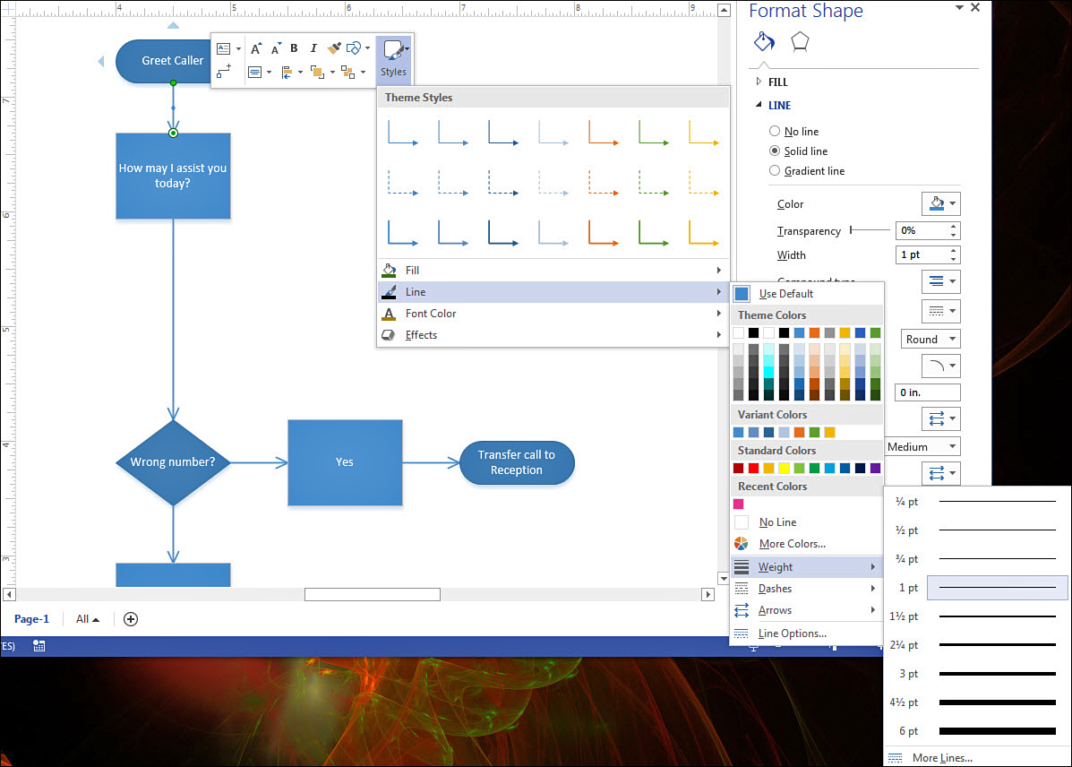
1. On your keyboard press Ctrl+A to select all items on the page. Right-click one of the selected shapes, and select Format Shape. Expand the Line section of tools under the paint bucket in the Format Shape pane.
2. As shown in Figure 7.12, modify the End Arrow type and choose a style. Notice how all selected connector lines immediately change to reflect this new choice.
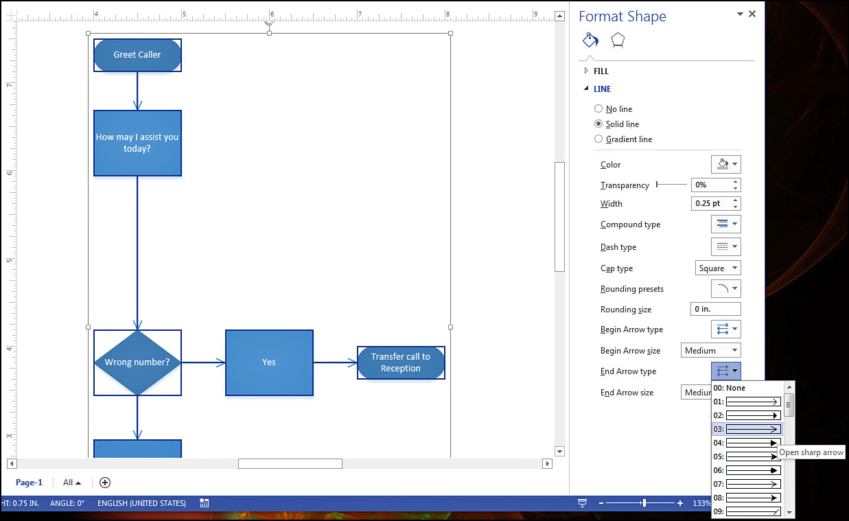
You can make additional formatting edits, such as line weight and color, transparency, and compound lines. As shown in Figure 7.13, you can also right-click a connector and select Styles and Lines to see many of the same format options.
Routing Styles
The routing style itself can be a straight line, right angled, or curved. You can right-click a connector to see these three available routing styles.
In the following steps, you modify these properties for a page.
1. Right-click the Page tab below your drawing and choose Page Setup.
2. Select the Layout and Routing tab (see Figure 7.14).
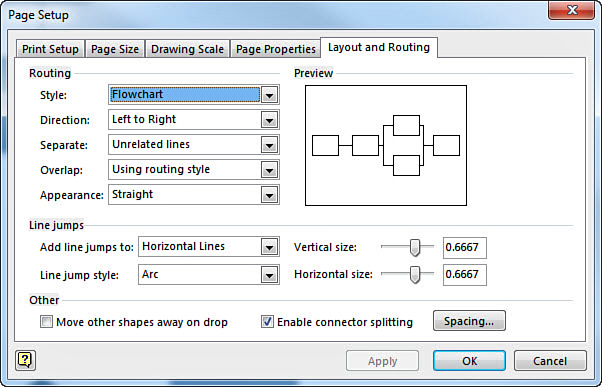
FIGURE 7.14 The Page Setup dialog box allows you to quickly change the routing style for the whole page.
3. Change the style using options in the drop-down menu.
Using Line Jumps
Line jumps refer to the behavior of your connectors when you have intersecting lines or overlap of your connectors on the diagram. The visual detail provided by the line jump makes it easy to follow the route of your connectors. In Figure 7.15, notice that the group of shapes to the right shows a path from Point G to Point H, and you can see where the line hops over a connector in the path. In the group of shapes to the left, no hop is visible, and this clouds the path a bit. Is this drawing indicating that from Point A you can go straight to Point B, or go to Point D? This emphasizes the role line jumps play.
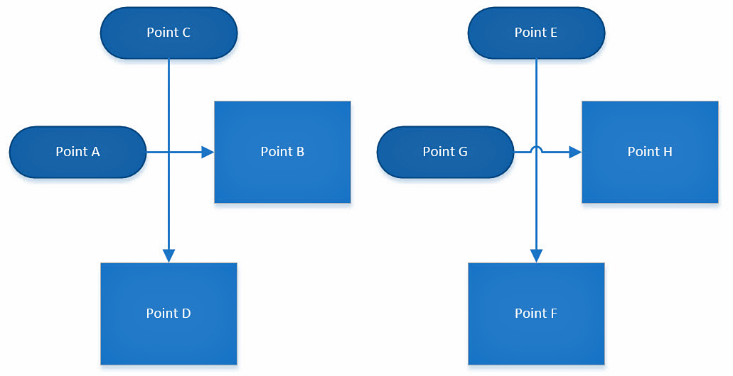
From the Page Setup dialog box and then on the Layout and Routing tab, you can see a section devoted to line jumps. You can control when to use them, their size, and the style used on that page.
• Arc
• Gap
• Square
• 2 Sides–7 Sides
Finally you can remove a line jump altogether from the page by selecting None from the Add Line Jumps To drop-down menu.
Manual Override
Until now, you have allowed connectors to be stretched and pulled on different routes by the way you position the shapes and the glue you are using. To add more finesse, you can use the control handles on the connector itself.
Connectors show end points, midpoints, and sometimes corner points. When you’re working with curved connectors, notice points that allow you to bend shapes. To experiment with these handles, place at least three shapes on a page. Use a connector to connect the two furthest shapes, and practice adjusting the routing by selecting the connector and pulling the handles (see Figure 7.16).
Now that you have experimented a bit with these basic adjustments, try holding down the Shift key when you click the handle. When you choose midpoints and corners on straight and right-angled connectors, a new and better-refined adjustment is possible. Notice on the midpoint of a straight connector that you now adjust a portion of the path instead of moving the entire connector.
Finally, if you hold down the Ctrl key when selecting mid and corner points, you see an angular adjustment. Called nonorthogonal angles, this adjustment should be used with caution because it can detract from a clean and refined diagram if used indiscriminately.
Tip
Figure 7.17 shows a few of the contortions you can put your connectors through. Although you may not use these manual adjustments very often, it is good to be aware of their presence.

Working with Connector Points
Generally, you will likely be happy with your results using dynamic glue between shapes and connectors. Even so, you may find the need to occasionally add a connector to a shape at a very specific point. As you have seen, shapes often have a set of predefined points that meet most needs when you use point-to-point glue. You are not limited to those predefined points, however, and it may be useful to know how to add connection points to shapes.
Adding or Removing Connection Points
To understand how this can be done, imagine that you are sending instructions for the correct setup of a workstation to a satellite office. The network switch is being sent with a configuration that requires the printer, server, and computer to be plugged into the correct ports on the switch. The general diagram in Figure 7.18 might serve to show in a general way how things connect, but it would be nice to show the specific ports by adding some points to the shape of the switch and connecting your devices to those specific points.
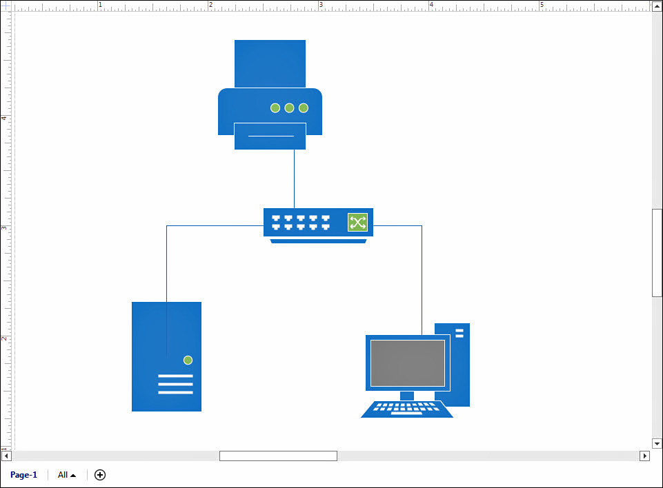
FIGURE 7.18 Occasionally you need your connections to be more specific than this generic set of instructions for a network switch setup.
1. Using the Basic Network Diagram template, open a new drawing.
2. Drag over a switch, a printer, and a server from the Network and Peripherals stencil. Add a computer from the Computers and Monitors stencil.
3. Arrange the switch in the middle and the other devices around the switch.
4. Check the View tab in Visio and make sure that Connection Points is selected under Visual Aids.
5. Zoom in on the switch, and select the shape until the ports are rather large and it is easy to precisely locate your points.
6. On the Home tab under Tools, select the Connection Point tool, which is represented by an X. Hover over the X to see a description of this tool (see Figure 7.19).
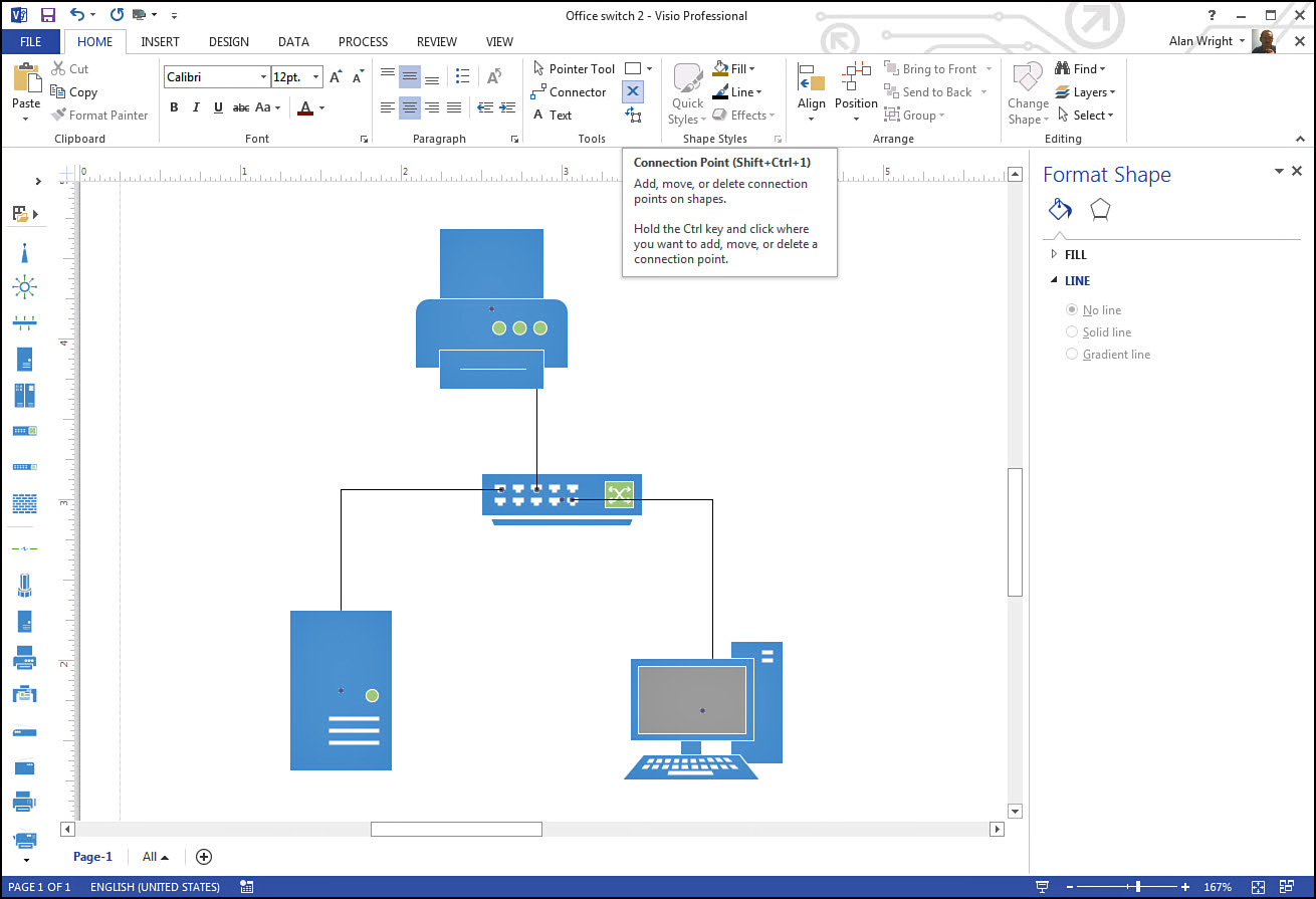
FIGURE 7.19 The Connection Point tool allows you to add custom points to your diagrams for point-to-point connectors.
7. Hold the Ctrl key and left-click a point in the switch shape to add a new point. This new point appears pink, indicating that it is selected. You can move or delete a selected point while using this tool. (This includes predefined points.)
8. Zoom back out and select the Connector tool. Connect the printer to the point you have just added. Repeat to select points for the server and computer shapes.
Adding and removing points to shapes is a little tricky and not something you are likely to use very often. Knowing how to use these tools can bring a bit more elegance to your diagrams and make you look like a Visio guru.