
10. Shapes: More Than Meets the Eye
In This Chapter
• Are shapes smarter than they appear?
• How can I peel back the layers on SmartShapes?
• How can I import pictures into my diagrams from the Insert tab?
• How do I let diagrams speak for me by inserting Excel charts?
• How can I use Vectored Graphics and AutoCAD drawings?
SmartShapes are an important feature of Visio that can easily be taken for granted. This chapter spends a little time looking at what makes them so smart and how you can access all that extra shape potential.
Although you can read about how Visio has lots and lots of shapes, it is a picture that’s worth a thousand words, right? Visio makes it easy to bring pictures and clip art into your drawings and even provides special tools for the job. You look at how integrated Excel tools allow you to insert and edit charts so that spreadsheet data can be visually presented in your Visio drawings.
Besides the common raster-based images you use every day, Visio enables you to work with vector-based graphics as complex as AutoCAD drawings. How can you work safely in Visio with these formats? That is also considered in this chapter.
Understanding Special SmartShape Features
Visio shapes have many properties that you have examined throughout this book. Because these properties allow for so much customization and functionality, they are often rightly called SmartShapes. Much of this flexibility is out of sight and you may rarely, if ever, need to change the shape data. A consideration of what makes a shape a SmartShape helps you understand the behavior exhibited by some shapes and opens you up to new possibilities.
What Is Shape Data?
The term shape data usually refers to information kept in shape date fields. To view this data you can right-click a shape to open the context menu and then select Properties, as shown in Figure 10.1. From the View tab you can also enable this Shape Data pane after selecting the Task Panes button.
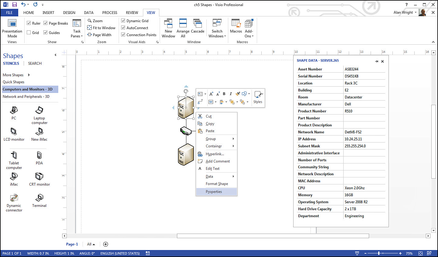
As you can see in Figure 10.1, a lot of information is recorded and stored right in the shape.
Right-Click Menus
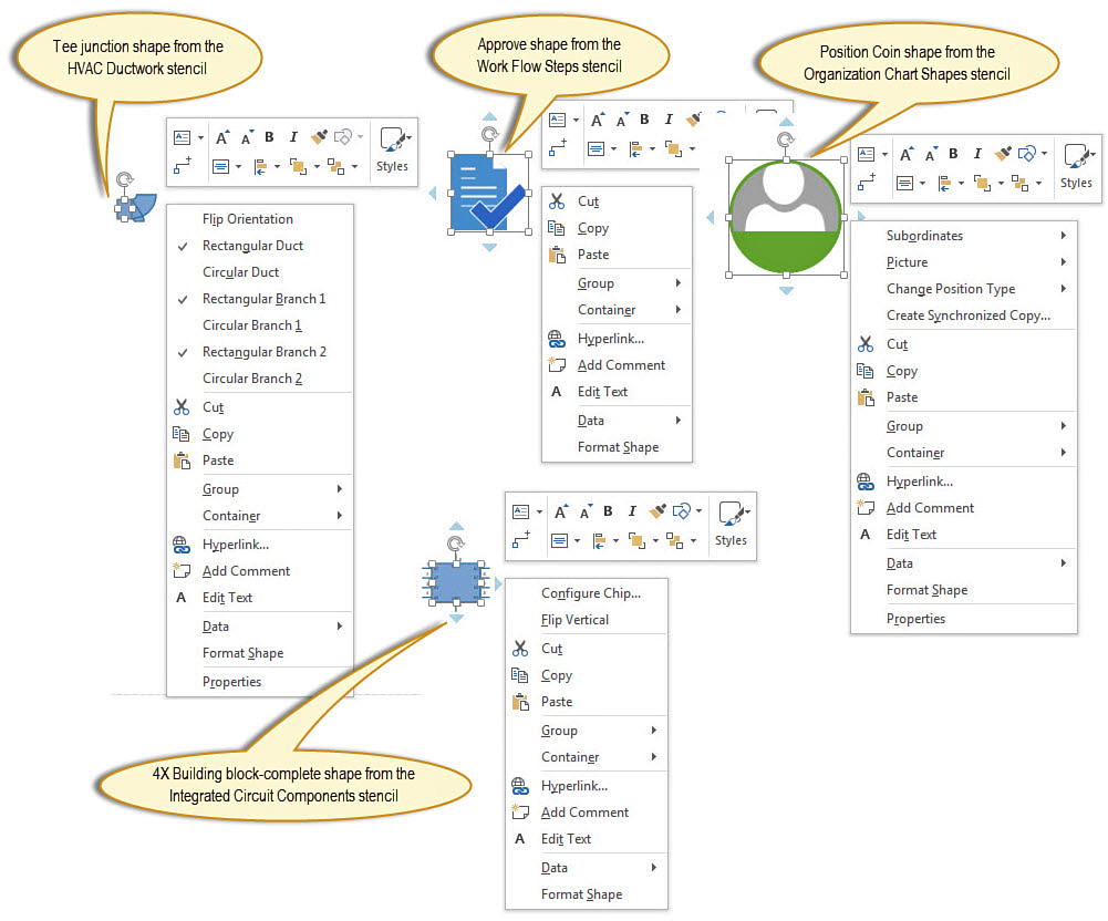
Another way to get an idea of how much data a SmartShape is carrying around is to look at the context menu. Notice in Figure 10.2 how the context menu reveals many special abilities for some shapes from different stencils. The top middle shape is a rather plain shape by comparison. When you see Properties listed in the context menu, it indicates that you can find additional information in the Shape Data pane, as shown in Figure 10.1.
Control Handles
Control handles are a standard feature for shapes when you are moving and resizing. You may see additional control handles from time to time that signal additional adjustments or purposes like glue points indicated for these handles. In Visio 2013 they appear as yellow control handles, and you find their purpose by hovering over them to reveal their tooltip, as shown in Figure 10.3.
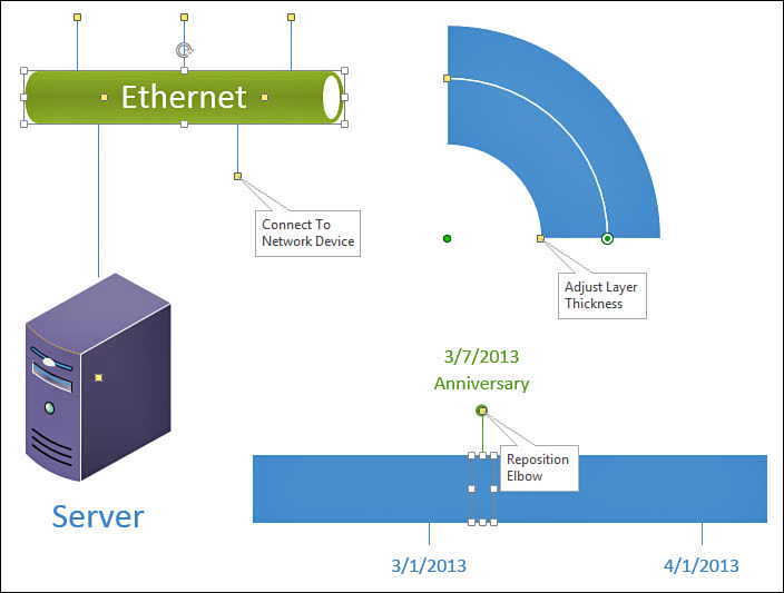
FIGURE 10.3 Hover over yellow control handles to learn what special control has been added to the SmartShape.
Hyperlinks
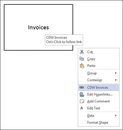
Shapes can provide a nice intuitive springboard to a website or network location by adding hyperlinks. Notice in Figure 10.4 that the shape labeled Invoices opens a network location. Selecting the Hyperlink option from the context menu allows you to name and point to a location. If a hyperlink is already established, you see Edit Hyperlinks and you can edit or add additional links. This is invisible on a SmartShape until you hover over the shape, as shown here.
Smart Tags
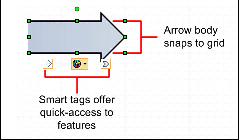
Not as common, and sometimes called action tags, smart tags are a SmartShape feature that you might come across eventually. A few developers add this feature to shapes, and they can provide additional actions or options from a clickable drop-down menu. Although it is similar to the context menus we rely on, one advantage is the presence of a visible indicator that actions are available here. Notice an example of a shape that has been created with Smart Tags from Chris Roth’s Visio Guy website in Figure 10.5.
Import External Images
Because Visio communicates using visuals and graphics, it is natural to want the ability to work with graphics that originate outside of Visio. Not only does Visio allow for this, but quite a few built-in features simplify this for you.
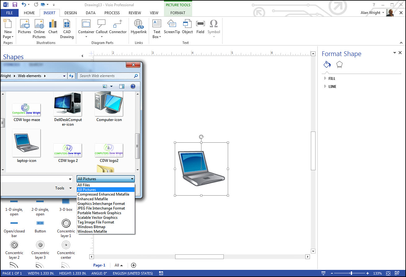
Images can be copied and pasted into Visio. If you look at the Insert tab you see a group of tools labeled Illustrations, shown in Figure 10.6. You can browse to a file that is filtered for all pictures. Selecting the image file allows you to add it to the open drawing window, as was done here with the laptop-icon.png file.
What You Can Do with Images
After you paste and insert an image into Visio, you can work with it further using the Picture Tools Format tab that opens automatically. As shown in Figure 10.7, you can use Line tools to outline the shape, adjust the Z-order, and rotate and crop your image. The first tool group labeled Adjust allows you to adjust brightness, contrast, autobalance, and reduce the size of the picture using Compress Picture.
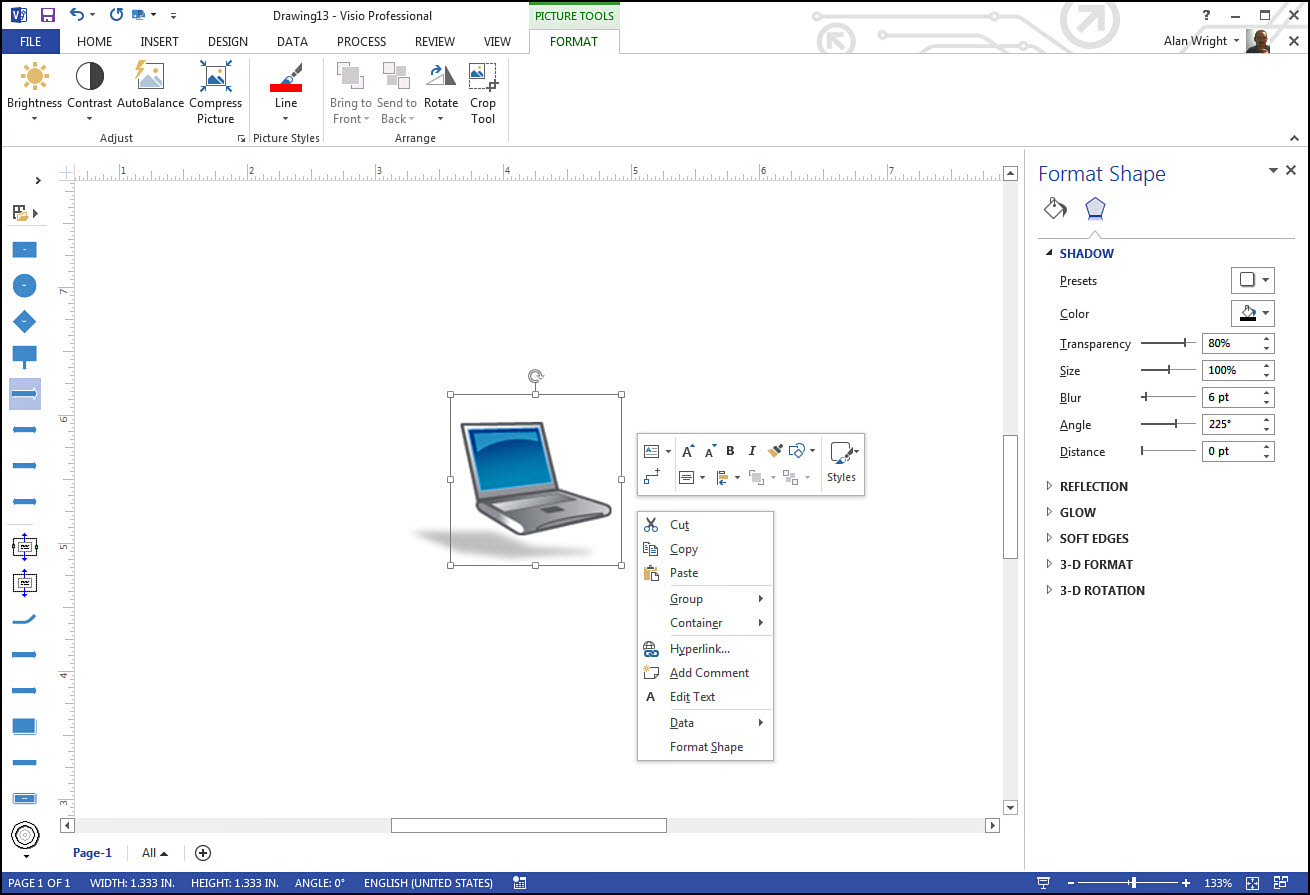
FIGURE 10.7 Inserted images are automatically considered to be shapes and can be modified with Picture tools or standard shape tools.
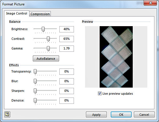
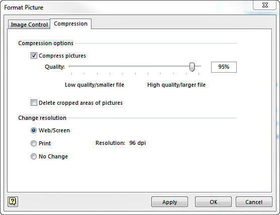
This Adjust tool group is better suited to photographs, and selecting these tools launches the Format Picture dialog box shown in Figure 10.8.
Besides the special picture tools, you can use the Format Shape pane to further modify the images because Visio already considers the image to be a shape. Notice in Figure 10.7 that a shadow was added, and a right-click reveals the familiar shape options that are available for this image. Because Visio considers the image to be a shape, you can resize using the eight control handles for size and movement. The Rotate handle works as expected.
Resizing Images
One downside to adding image files to your Visio drawing is that picture files can be quite large. With cameras and smartphones commonly taking 5MP to 16MP pictures, the size of the file is far larger than needed for a Visio diagram. Inserting a few of these uncompressed high-quality pictures can have very serious consequences if you use this type of drawing on a website—or even try to send it via email.
To avoid the hit on performance that accompanies large files, you can use the Compress Picture tool to quickly adjust the resolution. Shown in Figure 10.9, the slider provides a way to manually compress the picture size; the lower Change Resolution option buttons optimize the resolution of your picture for Web/Screen or Print quality.
 Tip
Tip
If you notice your Visio drawing has a slower speed than expected when redrawing or loading, make sure that there are no uncompressed image files. Make it a habit to compress to optimize the resolution when you paste or insert image files.
 Caution
Be careful when compressing images that will be resized and used at a larger size later. Too low of a resolution appears pixelated if you try to make it larger after optimizing. Also, optimizing for screen size (96dpi) is a lower resolution quality than print (200dpi). If you think the shape may be used at a larger size, consider optimizing at that larger size.
Working with Clip Art
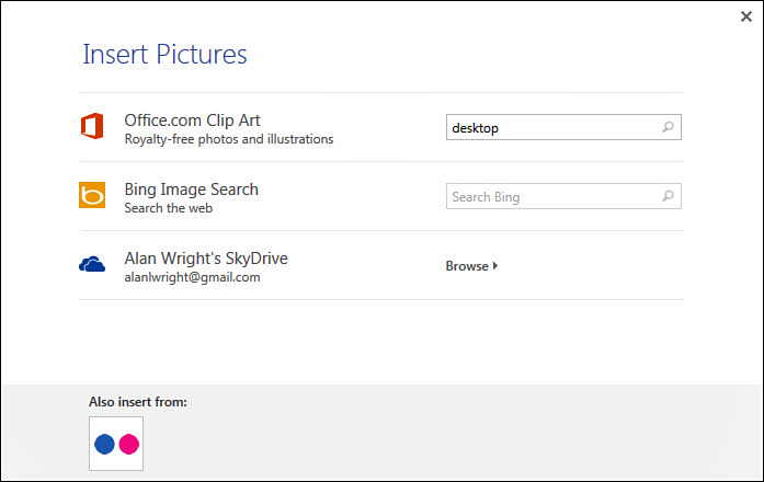
Besides images we have stored locally or on a network, we can search for additional images and clip art from the Insert tab and the Online Pictures tool. This opens the Search interface shown in Figure 10.10. Notice you can search Office.com Clip Art and Bing Image Search. You may see additional options, such as browsing your SkyDrive, if you log in with a Live ID or search attached services like Flickr (see Figure 10.11).
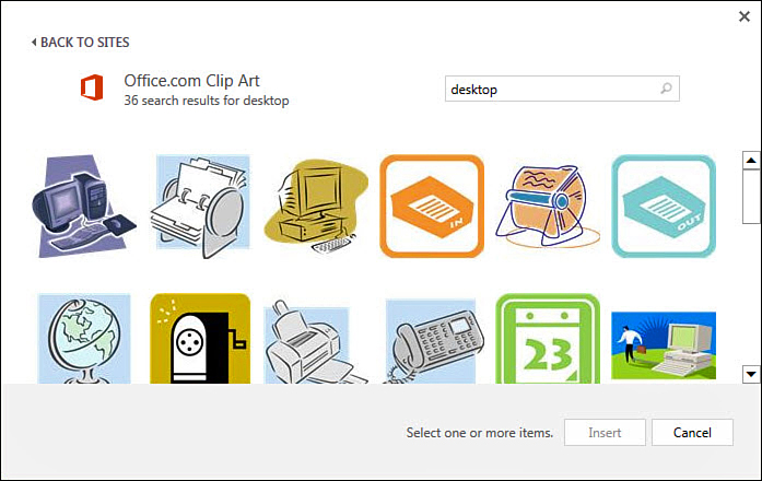
Images found using this tool are inserted with the same Picture Tools Format tab, which enables you to fine-tune your selection. Images you use may be vector based or bitmapped and Visio will work with both. You should be aware of how each behaves when you resize an image. Just remember that bitmapped images can lose their sharpness quickly when they are resized while vector-based images handle size changes with no loss to their image quality.
Caution
By default you are provided with search results that keep you out of trouble with respect to licensing and usage rights for the images you find. Make sure that images you insert into your drawings are free for you to use. Some images can have strings attached related to the paying of royalties or limits on usage.
Using Excel Charts
Visio has the ability to insert and edit Excel charts. The way Visio presents this depends on the version of Excel you installed because it actually pulls tools from Excel.
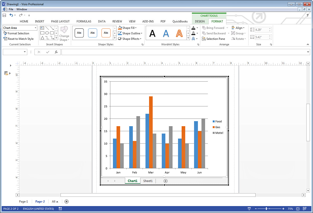
Select the Insert tab and Charts from the Illustrations tool group. As shown in Figure 10.12, Visio opens a session of Excel 2013 complete with the ribbon interface for Excel. (You may not even see a ribbon when using an older version of Office, although the tools are available as menus.) The chart is selected, and you have the Excel ribbon and Excel tools for editing the appearance and contents of the chart. If you look closely at Figure 10.12, notice that the only Visio commands available are a menu bar with File and Window options.
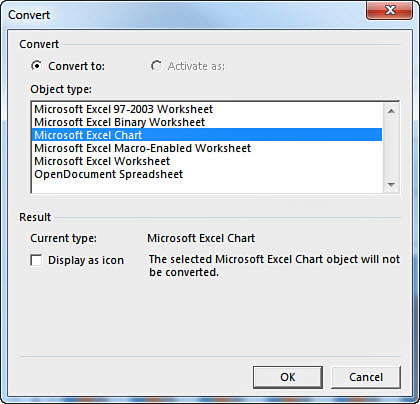
You launch into Edit mode by default when inserting a chart. While in Edit mode you can edit the spreadsheet and chart that accompany it. If you click outside of the chart, you go back to the familiar Visio ribbon interface, and the finished chart appears as a shape that is editable like any other picture shape (see Figure 10.13). If you need to edit the chart itself again, right-click and use the Chart Object menu to access the Edit, Open, and Convert options. The Open option opens the chart directly in Excel, and the Convert option allows you to change the format of the chart object from the choices shown in Figure 10.14.
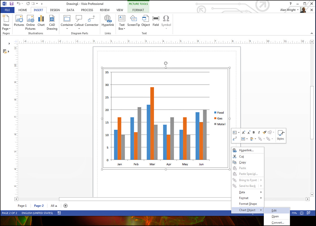
FIGURE 10.13 A completed chart has the properties of an inserted picture. To edit the chart, use the right-click menu that shows Chart Object tools.
Caution
Visio opens Excel system processes to edit charts, which can be pretty intense for computer resources. You might even see a few seconds of unresponsiveness. This seems to be a byproduct of the way Visio takes over the Excel application. If you have open Excel windows, watch for alerts to pop up that were initiated by the chart inserted in Visio.
Importing Scalable Vector Graphics
Vector-based graphics are images that differ from pixel-based graphics (also known as raster graphics) because they render the image based on paths or lines to form shapes rather than a fixed assemblage of dots. If you have ever seen an embroidery machine that can sew a logo onto a hat or jacket, you have seen vector-based graphics converted into paths for a sewing needle.
Because they do not need to add or remove pixels when resizing, vector-based graphics present cleaner images when resized, and they are used for higher end graphics work because of this versatility.
SVG formatted images allow for great flexibility in your drawings. If prepared correctly, they are seen by Visio as grouped shapes with lines and shapes that can be worked with individually once ungrouped. This allows you to use colors and other effects in the case of SVG formatted maps. Some SVG formatted graphics may not allow for this degree of editing and they may appear as a single shape because they retain a sharp image. In either case they are superior choices when you will resize the image.
To insert an SVG formatted image, open the Insert tab and select Pictures. SVG files are seen with the default All Pictures file type; however, you can choose Scalable Vector Graphics to refine your search.
Importing AutoCAD Drawings
AutoCAD (which stands for Automated Computer-Aided Drafting) drawings are unique vector-based drawings created with special software used for architectural and engineering plans and diagrams. The most common format is DWG. They have a few similarities to some Visio templates, and this allows for a certain degree of interchange using the CAD DWG drawing format. You can view, annotate, and even add content to CAD drawings.
Importing CAD drawings is a straightforward process. Use a sample DWG file that you likely already have.
1. Open a new Floor Plan template.
2. Open the Insert tab and select CAD Drawing. Browse and select the sample CAD drawing file named BLDGPLAN.dwg installed by default in the path C:Program Files (x86)Microsoft OfficeOffice15Visio Content1033. (This is the default 32-bit path Visio; you may need to look in the path C:Program FilesMicrosoft OfficeOffice15Visio Content1033 if you have 64-bit Office applications. The 1033 directory provided here is for English; you will see a different number if you have a different language version. German would install to a 1031 directory for example.
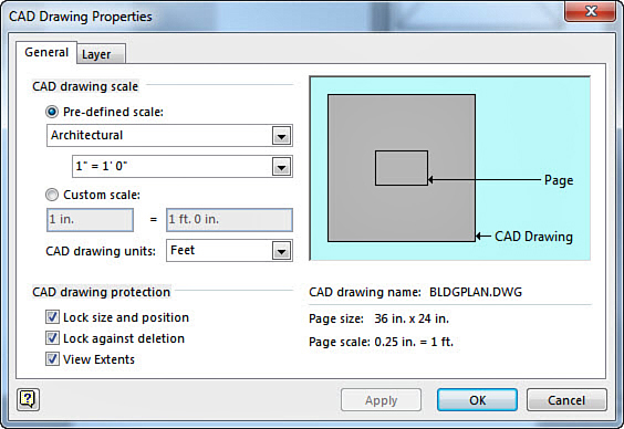
3. In the CAD Drawing Properties dialog box, confirm the scale from the General tab as shown in Figure 10.15. In this case, you open a drawing plan so you can try Architectural for the Predefined scale. The scale itself you may adjust after opening the drawing. However, you will find that this CAD drawing fits your page well using a scale of 1/4” = 1’. Click OK to insert the CAD drawing. Presto! You have a floor plan complete with furniture.
4. Because you want to add furniture, remove the furniture that was included in the bldgplan.dwg file. Right-click the CAD drawing, and select CAD Drawing Object and Properties to reopen the CAD Drawing Properties dialog box. From the Layer tab select Layer 12 and click the Visible column to show No, as shown in Figure 10.16. Click OK to apply.
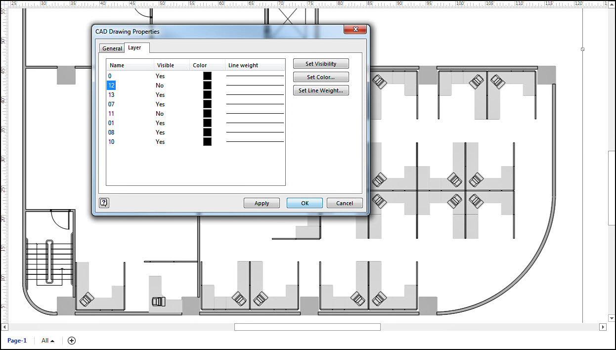
5. Compare the floor plan in Figure 10.16 to the one in Figure 10.17. Hiding the contents of a layer allows you to change content without permanently changing this file. This is important if you have further CAD work to do on the original file.
Based on the choices you made in the CAD Drawing Properties dialog box, you may not be able to resize or move the CAD drawing object. If the default Size and Position settings are left as Locked, you see the drawing as a shape in your drawing window and the control handles are grayed out. To make changes, you can right-click and select CAD Drawing Object and Properties to reopen the CAD Drawing Properties dialog box.
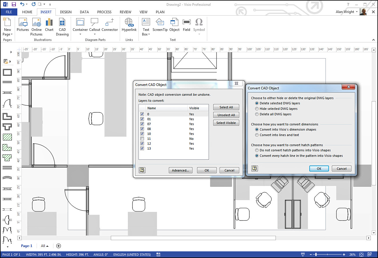
From the right-click CAD Drawing Object menu, you can also select Convert to transform the content on selected layers of the DWG file into individual shapes. There may be times when you need to do this, but it is not as common as working with the DWG file format. The options shown in Figure 10.16 show the Convert CAD Object dialog box and the Advanced window options to perform this conversion.
Caution
Converting a DWG converts the lines and shapes in the AutoCAD drawing to lines and shapes in Visio. This is a one-way trip. The output does not have any special properties and may be difficult to work with as a consequence. For example, objects may appear as a desk or computer, but Visio does not know them to be furniture items.
Adding Content to AutoCAD Drawings
After you have a CAD drawing inserted into your drawing window, you can add content from your stencils. In Figure 10.18 notice how easy it is to add furniture to a floor plan. The shapes even interact with the elements in the drawing without having converted anything from the DWG format.
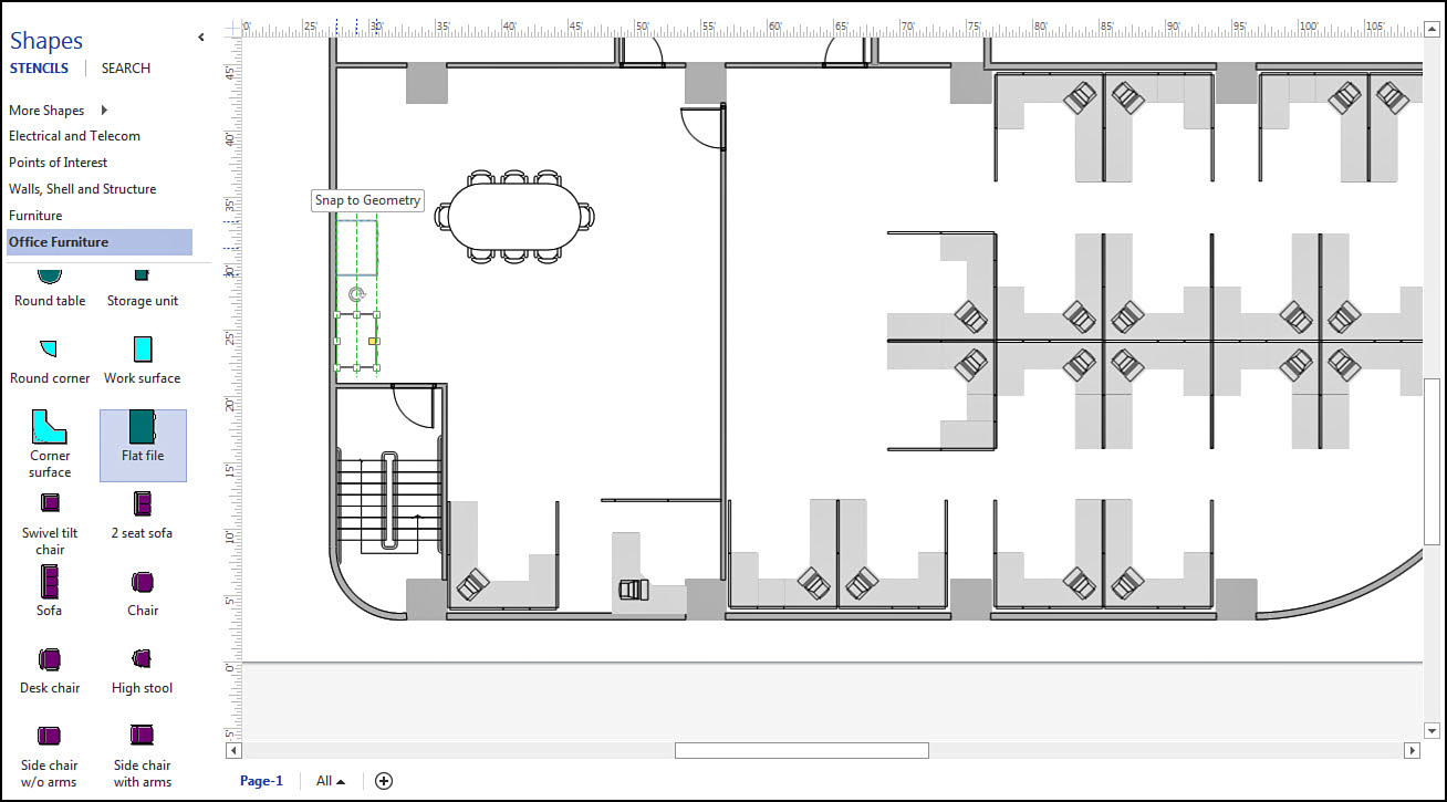
When you’re finished, save the file using Save As, and use the type AutoCAD Drawing, which saves this as a DWG formatted file. You can send this file to a person who has AutoCAD, and the file will open without any need to convert the drawing.