CHAPTER 15
MAKING A VEHICLE MODEL
In Chapter 9 we looked at creating skins, and during that process we created a skin for a cool runabout-type vehicle. In this chapter we’ll create the model itself.
Of course, there is a whole host of different vehicle types, such as those for the open road or off road, aircraft, hovercraft, ships, and so on. In most cases the methods used to create the vehicles can be used with any type of object. But different vehicle types have different capabilities and therefore may require some specialized accommodation for those capabilities in the models.
For example, if you want your vehicles to be drivable by a player-avatar that gets into the vehicle when you want to drive, then your vehicle will need mount points, which are special nodes or subobjects within the model that indicate where your player-avatar gets attached to the vehicle. Different vehicle types, makes, and models will have different needs in this area.
Then there are those special nodes that indicate where other game functions will happen. Wheeled vehicles need to know where the wheels are located, as well as information about how the springs and steering mechanisms are oriented.
Some vehicles might need nodes in their models to indicate to the engine where to generate engine exhaust smoke using particles. Flying vehicles may require nodes to help the engine generate contrails (condensation trails). The list goes on.
THE VEHICLE MODEL
In this chapter we are going to build a complete wheeled vehicle, the runabout, which will wear the skin you created in Chapter 9. Then we will insert it into a little test game so that we can carom about and drive our insurance rates through the roof!
The Sketch
I find the best way to start a new model is with a sketch. Doodle out some ideas, and keep working them up on paper until you get something that suits your needs. Then choose a view (Left or Right, Top or Bottom, Front or Back) that presents you with the highest number of intersections of lines to use as points.
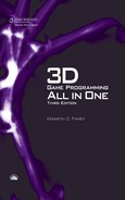
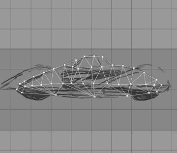
Figure 15.1
Side view sketch of the runabout.
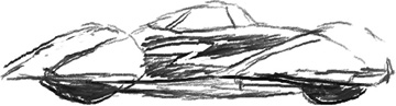
Figure 15.1 shows a sketch of the runabout from the right-hand side. Notice that it is really a sketch and not a drawing. As long as the general proportions and coarse features are present, it’s satisfactory. Now if you were going to model a real car, you might need to use a more detailed sketch or perhaps something that would qualify more as a drawing than a sketch. Then again you may not—it all depends on how much detail is necessary to suit your needs.
The Side view is the main sketch we will use to make our model. When modeling most vehicles, you will usually use a Side view as your primary source for extrusion modeling. The reason for this is pretty obvious. Most vehicles are longer than they are tall or wide. The symmetries of vehicles (how one side mirrors the other) tend to reflect around the longitudinal axis, the one that runs from the rear to the front of the vehicle up the middle.
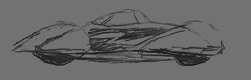
The Top view of the runabout is shown in Figure 15.2. The purpose for sketching this view is to provide a guide for your modeling efforts as they proceed. You will find yourself checking back against this drawing quite often.
One more useful thing is to make a copy of the Side view and, using Gimp, adjust the brightness of the image. This is because when we import the sketch into MilkShape, we don’t want the image to overpower any of the on-screen modeling marks we make. I find the best approach is to darken the whole image by around 40 to 50 percent and reduce the contrast by about 50 to 60 percent or so. Figure 15.3 shows the adjusted Side view. I keep the original sketches as they were so that I can print them out for reference purposes (and also just to pin up on the wall because it’s a cool artsy thing to do).
Figure 15.2
Top view sketch of the runabout.

Figure 15.3
Side view sketch adjusted for use in MilkShape.
The Model
So pour some jet fuel in the ol’ computer, grab the propeller, give it a whirl, and fire up MilkShape 3D again if it isn’t already running. If you need a quick refresher, you can jump back to Chapters 13 and 14. Set your MilkShape 3D GUI display to the four-view mode by choosing Window, Viewports, 4 Window.
Create a fresh new MilkShape document. It’s a good idea to save the empty file right now, just to get the path set up and establish the filename.
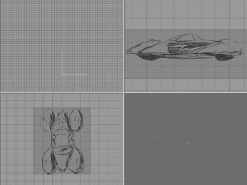
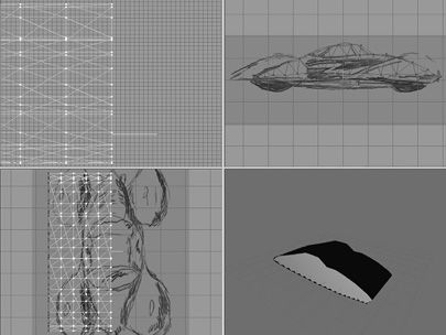
Then you want to import the side sketch as the background in the Side view (Upper-right view). Right-click in the Side view, and choose Choose Background Image from the pop-up menu. Select your sketch, and click OK. You can use my sketches if you want—they are located at C:3D3ERESOURCESCH15 ef_side_sketch.bmp.
Do the same thing for the Top view (Bottom-left view), using your own sketch or mine, found at 3D3ERESOURCESCH15 ef_top_sketch.bmp. Usually, only two views are needed, but you could also sketch in the third view if you want to.
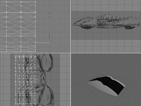
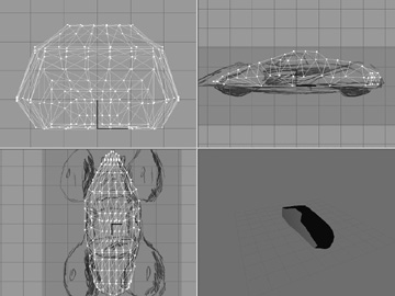
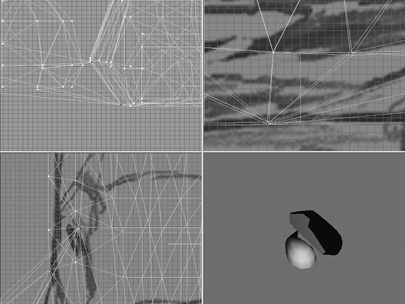
You should end up with something like Figure 15.4.
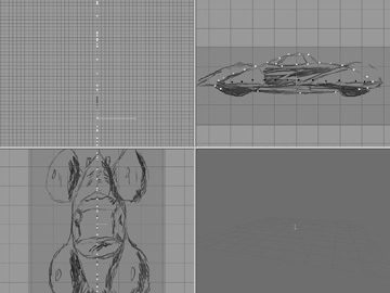
Figure 15.4
MilkShape windows with reference sketches.
So now we start.
Building the Body
First, we’ll build the body:
1. From the Model tab, select the Vertex tool, making sure that the Auto Tool checkbox is cleared.
Placing vertices may be the easiest and most fun job in the world. With the Vertex tool active, go to the view that you are going to use as your guide, and find a spot on a contour or line in the reference image that signifies a contour feature. This could be a turn, a point on a curve, a sharp corner, or anything else that forms the character of the contour. Click on that spot. Blam! You’ve stuck a vertex there. Now find another target. Blam! Keep on going. Blam! Blam! Blam! Don’t get all blam-happy though—too many vertices will yield too many polygons in the long run, as well as make it hard to create the polygons in the first place. It can be difficult to continue to see the shapes when a swarm of pixels is obscuring them.
2. In the Side view, start placing vertices at all the major corners and points around the edge of the car’s body—don’t do the fenders yet. Just click on the appropriate location to place the vertex. See Figure 15.5 for reference.
Figure 15.5
Placing vertices over the reference sketch.
Note
There is also a string of vertices across the “waist” of the body—in Figure 15.5 they are highlighted as black squares (they show red in MilkShape). These extra vertices are added for two reasons. First, they act as useful anchors for creating the faces that we’ll make later. And second, they help add more malleability to the model for shaping the sides of the car.
After we have the vertices placed, we move on to creating the faces joined by the vertices.
It’s important to remember that when we create faces using the Face tool that is found in the Model tab, we click three vertices in sequence to create one face. The order we click the vertices is important. To create a face or polygon that is oriented toward us, we need to select the vertices in a counterclockwise order, as shown in Figure 15.6. For most cases this is not hard to do, but it’s possible to get confused and lose track of the sequence. In this case you can use the Edit, Undo menu item to back up until the sequence is clear. You can also abort any three-vertex sequence by just clicking the Selection tool (or any other tool) and then clicking the Face tool again. Then you can start with a fresh trio of vertices.
Figure 15.6
Vertex order for creating faces.
The direction that a polygon faces is indicated by a mathematical construct called the normal, which is defined as being a line perpendicular to the plane of the face. The side of the face on which the normal is positive is the side that is facing the viewer, and this side is created when its vertices are used in a counterclockwise order.
There is another Face tool, available as a menu option in the Face menu. This tool differs from the Model tab’s Face tool in one important way. The Face menu Face tool doesn’t care in which order you select the vertices; instead, the manner in which the vertices were created dictates the vertex ordering and, thus, which way the face’s normal points. You can use whichever Face tool suits your needs. In this chapter we will only use the Model tab’s Face tool.
3. Starting at the right side (the front of the car), begin creating faces, moving to the left along the top as you proceed, including the window area, as shown in Figure 15.7.
When you reach the left side, you should have something resembling Figure 15.8.
4. After completing the top row of faces, start making faces along the bottom, from the left back over to the right (see Figure 15.9).
5. Finish up the faces for the side of the body. You should end up with something like Figure 15.10.
Figure 15.7
Creating faces starting from the right.
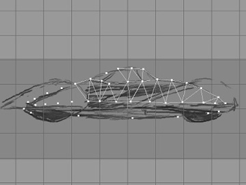
Figure 15.8
Finishing the top row of faces.
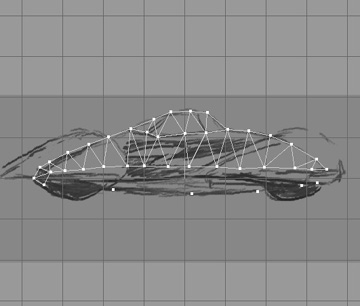
Figure 15.9
Working the bottom row of faces.
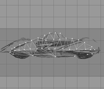
Figure 15.10
Completed plane of body faces.
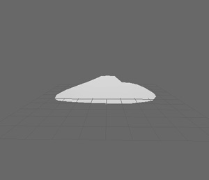
Okay, so now we have a plane of body faces. We want to make sure they are all oriented correctly. The quickest way to do this is to look at the output in the 3D Perspective view. Make sure the view (it should be the Bottom-right view) is set to either Flat Shaded or Smooth Shaded by right-clicking the view and then choosing either Flat Shaded or Smooth Shaded in the pop-up menu. What you should see is the outline of the body rendered in white or light gray, just as in Figure 15.11.
Figure 15.11
The 3D view of the initial body faces.
Tip
This is a looong one, so make sure you’ve got some popcorn handy!
Sometimes you end up with two overlapping faces: one oriented correctly and the other reversed. These are hard to catch until they start showing strange results when rendering, as the model grows more complex. There is another way to check for maloriented faces that is a little more involved:
1. Pick the Selection tool, and set it to Face mode. Make sure that the Ignore Backfaces checkbox is selected.
2. Now use the Selection tool to select all the faces by dragging the selection rectangle around all of them. This will highlight all the faces.
3. Now choose Edit, Hide Selection. All the correctly oriented faces will vanish, leaving behind only the ones facing the wrong way.
4. To fix the problem, unhide all the hidden faces, clear the Ignore Backfaces checkbox, and select all the faces again. This will select all correct and incorrect faces.
5. Then choose Face, Reverse Vertex Order. This will make the good ones bad and the bad ones good. Still with me?
6. Okay, now deselect everything by clicking the Select tool in an open area, and select the Ignore Backfaces checkbox again.
7. Drag select over all the faces one more time. Now only the faces that were originally incorrect will be selected.
8. Choose Face, Reverse Vertex Order with those faces selected.
9. Then for one final time, clear the Ignore Backfaces checkbox, select all the faces, and choose Reverse Vertex Order. This should flip all faces back to the correct orientation. If this reminds you of manipulating a Rubik’s Cube, then you think a lot like I do!
So now we’ll move on to adding some width to the body.
10. Choose the Selection tool, and set it to Face mode.
11. Select all the faces.
12. Click the Extrude tool, and fill in the X entry of the XYZ boxes with the value −10.0 (that’s minus ten point zero). Leave Y and Z at 0.0.
13. Click the Extrude button to the right of the XYZ boxes. You should get a new set of polygons negatively offset in the X-axis by 10 units, as shown in Figure 15.12.

Notice the way that the image in the 3D view looks. Now the body has some depth to it. It’s not just a plane of faces anymore.
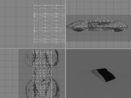
14. Repeat step 9 four more times, until you get five segments, as shown in Figure 15.13. Warning: do not click on any other tool or in the edit windows. After the fifth extrusion you want to end up with the body faces still selected.
Figure 15.13
After extruding the body faces five times.
15. The body faces should still be selected if you got my warning in time. Choose Edit, Duplicate Selection.
16. Click the Move tool, then go to the Top view at the lower left, and drag the highlighted faces (these will now be the copies, not the originals) to the right, clear of the extrusion segments, so that you get something like that shown in Figure 15.14.
17. Choose Face, Reverse Vertex Order.
18. Using the Side views and Top views, align the vertices of the copy of the body faces with their counterparts in the main body.
Figure 15.14
After duplicating and moving the copies.
19. In the Top view drag the body face copy over to the right edge of the rest of the body polygons. Align the vertices as best you can by eye.
Tip
We want to make sure that the vertices in step 15 are perfectly aligned. To do this, we’ll scale our entire model up. Making our model larger in relation to the grid allows us more precision with the grid. This will help ensure good results when we snap our vertices to the grid, which is going to happen shortly.
20. Select the entire set of polygons in all the faces, and then use the Scale tool to make the entire model four times larger.
21. Select the entire model in vertex selection mode, and choose Vertex, Snap To Grid.
22. Choose Vertex, Weld Vertices.
23. Scale the model by 0.25. This will restore the model back to its original size.
24. In the Top view make sure the entire model is selected, and then use the Move tool to drag the model over the sketch so that it is aligned around the longitudinal center of the car in the sketch. You should now have a model that looks like that shown in Figure 15.15.
Figure 15.15
Scaling the nose of the runabout.
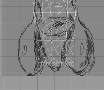
25. In the Top view select the bottom nine rows (or forwardmost nine rows) of vertices. This means that you need to ensure that the Select tool is in Face mode. If you haven’t placed your vertices exactly as I did, don’t sweat it. Just make sure that you select all of the vertices from those at the front of the car, back to the top of the windshield. Look ahead to Figure 15.16 to see what I mean, if it still isn’t clear.
26. Use the Scale tool to scale the selection to 0.9 in the X-axis only; leave the other values at 1.0. Figure 15.16 shows the result of this operation.
27. Change your selection to be the bottom eight rows, and scale to 0.9.
Figure 15.16
After scaling the bottom nine rows.
28. Repeat the decrementing and scaling of the selection, reducing your selection vertices one row at a time until you run out of victims…ummm…I mean vertices. You should now have something that resembles that shown in Figure 15.17.
29. Repeat this iterative scaling process for the rows of vertices as seen in the Top view at the other end of the car body, until it, too, tapers, as shown in Figure 15.18. You may find it necessary to manually move a few vertices at either end to achieve the appropriate amount of taper.
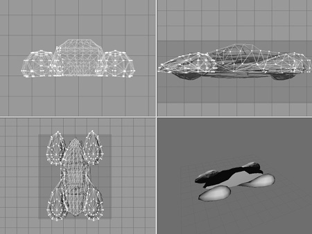
30. Now perform the same sort of iterative scaling operations on the Front view of the car, getting it to look something like the view shown in Figure 15.19.
31. Next, use the Selection and Move tools to place the car so that it is centered around the origin (0,0,0), as shown in Figure 15.20. The axis “bug” at the origin has been enhanced as thick black lines to emphasize its location.
32. Finally, select all the polygons and use the Groups tools to regroup all polygons into a single group—name it “body”.
Figure 15.17
After scaling the nose.
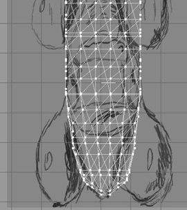
Figure 15.18
After scaling the tail.
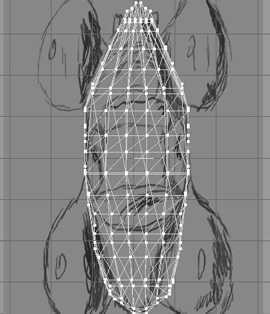
Figure 15.19
Shaping the Front view.
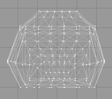
Figure 15.20
Centering the Front view.
Building the Fenders
Next, we will tackle the wheel well and fender assemblies.
1. Hide the body group.
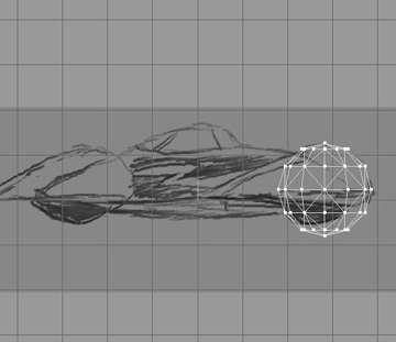
2. On the Model tab, select the Sphere tool, and create a sphere that matches the forward curves of the forward fender, as shown in Figure 15.21.
3. Select the bottom two rows of faces, and delete them. Then move the bottom row of vertices up a bit, to get something that looks like Figure 15.22.
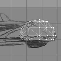
4. Select the leftmost three rows of vertices, and move them farther left, as shown in Figure 15.23.
5. Continue to reshape the fender to match the sketch as shown in Figure 15.24, until you are happy.
The next bit is a little tricky, so move slowly. We want to drag certain vertices from the fender over to the exact position of vertices on the body. The vertex rows we want from the fender are the two bottom ones, and we are interested in the vertices on the body side. By dragging them over to the body, we create a fairing-cum–running board sort of affair.
Figure 15.22
Lopping off the bottom of the fender sphere.
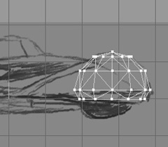
Figure 15.23
Stretching the fender.
6. Unhide the body.
7. Drag the fender away from the body so that it is in the clear in the Top and Front views.
8. Select the vertices and drag them, one at a time, as shown in Figure 15.25. The vertices are on the two bottom rows and are the ones that face the body.
Make sure to place the vertices exactly where they mate with a corresponding vertex. A close-up view is shown in Figure 15.26.
Figure 15.24
Shaping the fender.
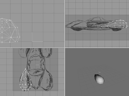
Figure 15.25
The fender vertices.
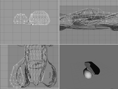
Figure 15.26
Close-up of moved vertices.
9. After each vertex is placed with a mate, use Snap To Grid to make sure they are exactly coincident, and use Weld Vertices to convert each pair of vertices into one vertex. Once you have done this for all the appropriate vertices along the fender bottom, you will get something like Figure 15.27.
10. Finally, move the fender back to a position that matches the sketched fender in the Top view, as shown in Figure 15.28.
11. Repeat steps 2 to 10 for each of the other fenders. Remember to hide the body and the other fenders when necessary to remove clutter from the screen. You should end up with the finished car, as shown in Figure 15.29. But we aren’t done yet!
We need to rescale the car. I like to size my models so that the exporter doesn’t need to scale them. Select your entire model (all vertices, or all faces, or all groups—it doesn’t really matter) and move it so that it is centered over the axis bug, with the bottom sitting about 0.3 units above the X-Z plane (as seen from the Side view). The X-Z plane serves as the ground for us at the moment.
Figure 15.27
All vertices moved.
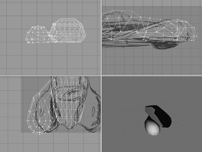

Figure 15.29
All fenders and body completed.
Now scale the car in the Y-axis so that the roof of the car is about 2 units above the ground, while the bottom is still about 0.3 units above the ground. After that, scale the car in the X-axis so that the front bumper is about 3 units in front of the axis bug, and the rear bumper is about 3 units behind the axis bug.
Save your work.
The Mount Nodes
In Chapter 14 you learned how to make a skeleton for an animated character in MilkShape using joints. In this section we are going to use the same feature, the joint, to create nodes that tell Torque where to mount certain things on models.
1. As shown in Figure 15.30, create four unconnected joints, or mounts, on the four corners of the car where the wheel hubs would be. To ensure that the joints are unconnected, you need to use the Select tool to deselect each node after it’s been created.
2. Name each of the joints with the names shown in Figure 15.30, with hub0 being the left front joint.
Figure 15.30
Mounts on all four corners.
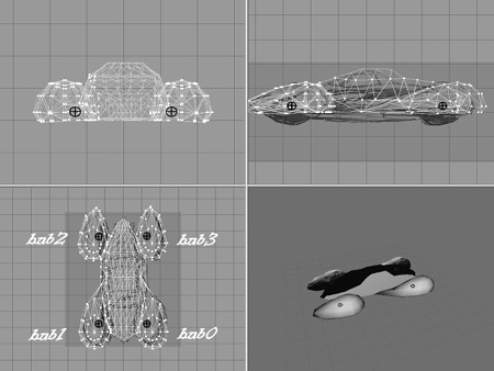
3. Add two more unconnected joints to the locations shown in Figure 15.31. Name the front one “eye” and the rear one “cam”.
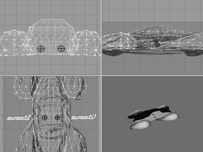
4. Finally, add two unconnected joints to the locations shown in Figure 15.32. Name the one on the right (the left-hand seat position) “mount0” and the other one “mount1”.
Now, the last two pairs of mounts are used for different, and mutually exclusive, purposes. The eye and cam mounts are used for games where the car becomes the player’s avatar. The sample racing game that comes with Torque works like that. The eye node located at the point of the eye mount is the normal first-person point-of-view location for the view’s eye. The cam node is for the third-person point of view; the actual camera is offset from the location of this node and so is usually actually behind and above the vehicle.
The mount0 and mount1 mounts are used for games where the player’s character actually gets “in” the vehicle; they specify where the player’s avatar will be mounted.
Figure 15.31
Eye and camera mounts.
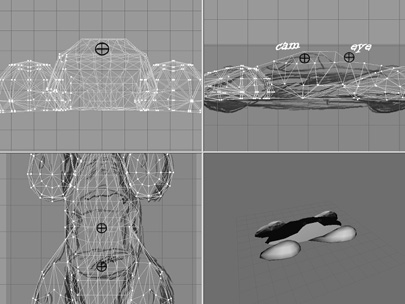
The game continues to use the player’s avatar’s camera and eye nodes. You saw those in use back in Chapter 14.
Skins
Chapter 9 covered the subject of skins and UV mapping, so I refer you back there to map the textures for your new car. You can find a copy of the skin to use at C:3D3E RESOURCESCH15 unabout.jpg. Create a new folder called “runabout” in the game folder artshapes, and put the skin file you created, or the premade one, in this new folder.
Collision Mesh
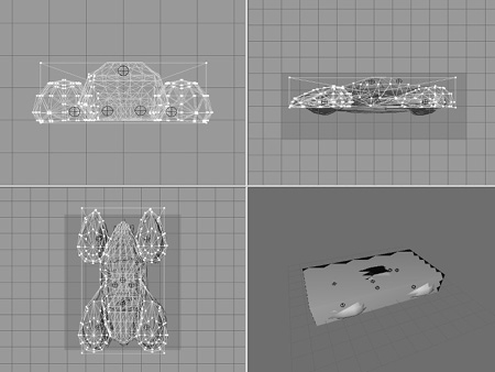
For all objects except player models, we need to create at least one collision mesh if we want the game engine to detect when it collides with another object, so use the Box tool in the Model tab to create a box that surrounds the vehicle, as shown in Figure 15.33.
The new box will have a name like Box01 in the Groups tab, and will be selected by default immediately after you create it. Name the collision mesh “Collision-1”. Collision meshes need to be named “Collision-n”, where n is a non-zero integer. You can have more than one collision mesh if you like, so number them as you create them, starting at 1, and incrementing by one each time you add one.
You should also hide the collision mesh and then save the model before exporting the model.
Collision Meshes
Collision meshes need to be convex hulls if they are to work correctly in Torque. A hull in this context is identical to a mesh. A convex hull is a mesh that has no “dent” in it—no areas where the mesh surface seems to go inward into the mesh.
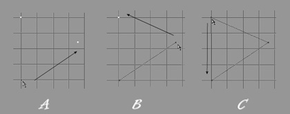
The following illustration should help in understanding.
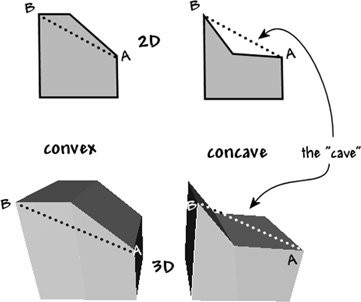
In the illustration, there are two 2D shapes at the top. The one on the left is convex, and the one on the right is concave.
Notice how a line drawn between A and B in the convex shape travels completely through the interior of the shape? With a convex shape, any line drawn between any two vertices will always pass entirely inside the shape. Always.
Now look at the concave 2D shape in the upper-right portion of the illustration. Line A-B in this case travels outside the boundaries of the shape. In fact the line segments of the shape running from A to the vertex between A and B and then on to B form a little indentation—something like a cave.
In fact, that is an easy way to remember which is which: Con cave shapes have caves. Con vex shapes don’t.
The bottom two shapes are 3D versions of the top shapes. You will probably find it harder sometimes to spot a concave 3D shape. But just remember the “cave” and you will do fine.
The bottom-left 3D shape would work fine as a collision mesh in all ways. The bottom-right one would not. It might work in certain special cases, such as for collisions with player characters, but projectiles would not detect the mesh, and hence not collide with it.
THE WHEELS
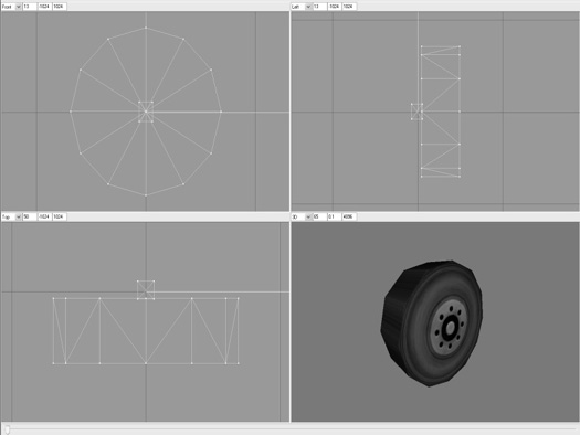
Of course, a cool car needs cool wheels. There’s not much to them, so I invite you to model your own wheel for use on the car. You, of course, may decide to make a complex model, but there is really no need—a lot can be done with a decent skin. A collision mesh is not needed, but do make sure that the wheel is oriented so that in the front wheel, you see the roundness of the wheel, hubcap and all. In the Side view (Upper-right view) you should be looking at the tread of the tire on the wheel, and the inside of the wheel (the hub) should be on the left. This is not the same as they would be oriented if you modeled the wheels directly onto the car. Also ensure that the axle of the wheel and the midline of the tire are aligned with the origin bug, unless you include a hub assembly for the wheel. If you do include a hub, align the hub with the axis bug instead of the wheel.
Make sure that the wheel is about 1.5 units in diameter, and about 0.4 units wide (or thick). Figure 15.34 shows a simple low-poly wheel, and how it should be oriented in the various views. Not that the model origin (0,0,0) is centered on the hub. When Torque mounts this wheel to the car, the origin of each wheel that is mounted is aligned with the location of the corresponding hub node in the car model.
TESTING YOUR RUNABOUT
In order to test the runabout, we first need to export it from MilkShape. We will use the built-in exporter for this task, since it is more up to the job and has fewer settings and stuff for us to get wrong.
1. After saving your work, export your model from MilkShape using the DTSPlus Exporter. Choose File, Export, Torque DTS Plus.
2. Use defaults, but make sure they are correct. You want to have Output dump file and Copy textures checked, and Use .cfg File cleared. Set the Scale to 1. The other settings don’t matter.
3. Click on Export DTS to export your runabout to DTS format in the game folder at artshapes unabout unabout.dts.
4. Open your wheel model, and export it as artshapes unaboutwheel.dts. Keep the same settings as for the car.
Figure 15.34
Mountable wheel in MilkShape 3D.
If you didn’t create a wheel of your own, you can copy the one at RESOURCES CH15 into artshapes unabout. Make sure you copy both the wheel model and its texture file.
Next, you need to edit the script that controls the vehicle so it will look for your model and not the default one.
1. Locate the file artdatablocksvehiclesdefaultCar.cs, and open it with Torsion.
2. Find the line (around line 101 or so) that says this:
shapeFile ="art/shapes/buggy/Buggy.DAE”;
Replace it with this line:
shapeFile ="art/shapes/runabout/runabout.dts";
3. Then find the line (around line 74 or so) that says this:
shapeFile ="art/shapes/buggy/wheel.DAE”;
And replace it with this line:
shapeFile ="art/shapes/runabout/wheel.dts";
4. Save the file.
Okay, now it’s time to run the FPS Example demo. We’ll launch the game directly from the hard drive, instead of from the Torque Toolbox, just for giggles.
1. Browse to C:3D3EDEMOExamplesFPS Examplegame, and double-click the executable file FPS Example.exe. Click on the Continue Using Demo button when the splash screen appears.
2. When the main menu appears, click the Play button.
3. Choose the Deathball Desert mission.
4. Click Go!.
5. After the game loads, you might need to remove some objects from the Scene tree using the World Editor, just as you’ve done before if you haven’t already done it for yourself. (Press F11.) We need to remove the entire Static Meshes and Particles folders.
6. After clearing out an object or two, make sure to use the Free Camera to fly over to a piece of terrain that looks friendly to automobiles. (Press Alt-C to toggle between Player and Free Camera.)
7. In the Scene tree, click on the Library button, and make sure that the Scripted tab is selected.
8. Double-click the Vehicles folder to open it and then double-click on the Default-Car to insert it into the world at the point where you are looking down at the terrain.
9. Toggle back to Player Camera, exit the World Editor (Press F11) and then fly over to near the car, and spawn your player there using the F7 key.
10. Run up to the car and bump into it. You should find yourself mounted into the car and driving it around. If you press the Tab key, you will get a third-person view from behind and above.
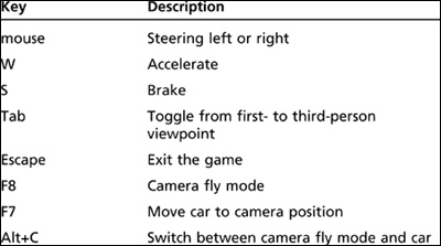
Table 15.1 Torque Racing Demo Controls
MOVING RIGHT ALONG
Building the model is only half the battle—well, maybe three-quarters. There is still the matter of defining the vehicle’s characteristics, like mass, drag, speeds, particle generators, collision handlers, and so on. You take care of these things in scripts that run on the server.
To do the testing you just did, you used the existing demo buggy script that comes with the Torque Engine and simply substituted our model in place of the dune buggy. It looks like a roadster but drives like a dune buggy! In fact, you will recall that you had a test-drive of a dune buggy back in Chapter 9.
Later, in Chapter 22, we will create the script that will define the behavior of the vehicle that we’ve modeled here. At that time we’ll also tweak some of its riding parameters and its response to user inputs and game environment stimuli.
Coming up next, in Chapter 16, we’ll continue with MilkShape and make some weapons and other items.