CHAPTER 17
MAKING STRUCTURES
There are quite a few different options available to the game developer when creating objects for use in a game. We’ve already seen how to make things like trees and weapons using MilkShape to create DTS-type shapes. But what about complex structures, like buildings and bridges?
Well, you can also use DTS shapes for those, making sure to create multiple collision meshes where needed. Buildings have a lot of surfaces that either you can walk on or at the very least you can’t walk through. So you will spend a great deal of effort creating collision meshes. This is a real issue for structures that are interiors. Bridges and ramps are not usually such a big deal when it comes to collision, but you still have the collision mesh workload.
Fortunately, there is a solution to this problem. In Torque another kind of object is supported—a DIF-type object, also called an interior. Now, using the word interior is a bit misleading, because you could (and probably will, at some point) use the same kind of object for complex structures that aren’t really indoor locations but do have many collidable surfaces. Therefore, I prefer to use the word structure to describe DIF objects.
Anyway, once-upon-a-time, the good folks at GarageGames decided that they really needed a CSG (Constructive Solid Geometry) tool that was more empathetic to the way the Torque Engine likes to do things. One of the most important of these things was cross-platform compatibility. Torque runs on PC (Windows), Macintosh, and Linux. So GarageGames, spearheaded by Matt Fairfax, teamed up with some bright and industrious fellows named Dave Wyand, Tom Brampton, John Kabus (aka Bob the C Builder), and Ron Yacketta, and scoped out a tool called Torque Constructor. Constructor is made with the Torque Engine, available for Windows but not (sadly) for Macintosh or Linux in the foreseeable future!
That was the good news. The bad news, if you are CSG modeling fan boy (I am, sort of), is that recently during the development of Torque 3D, the powers-that-be decided that CSG modeling should be deprecated (a fancy word meaning “not officially used anymore, even though it will still work”). Well, to me, CSG modeling as a work-flow issue is still important enough to warrant keeping a CSG tool like Constructor in this book!
I need to point out that interior lighting as used by CSG models in Torque prior to Torque 3D is not supported by the engine anymore, at least not in the original sense. DIF-portals don’t work—but there is a newer more useful version of portal zones that does do a similar job in a more encompassing and complete way. That’s an advanced topic outside the scope of this book.
Also, and this is very important, if you have any DIF files that were used in previous version of Torque, you can’t use them in Torque 3D. You will have to rebuild your .csx or .map source files into new .dif files. It’s a minor annoyance, but one that you need to stay on top of, for your peace of mind.
CSG MODELING
In the 3D graphics world, tools like Constructor and others that I’ll mention here in passing (including Hammer and 3D World Studio) are known as CSG Modeling tools. CSG stands for Constructive Solid Geometry, where 3D models are built out of things called brushes and models are built up using a collection of 3D brushes.
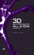
A brush in this sense is like a building block. You select a particular brush (also called a polyhedron) for a particular need and apply it to your model. There is a small set of shape primitives that serves as the basic brushes (see Figure 17.1): the cube (or box), the cylinder, the cone (or spike), and the ramp (or wedge). Some programs also include the arch and the sphere, as shown in Figure 17.2. Each of these primitives is a closed 3D solid.
Figure 17.1
Cube, cylinder, cone, and ramp solids.
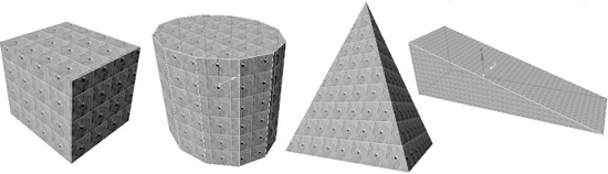
Figure 17.2
Arch and sphere solids.
Note
Now, when looking at the third object from the left in Figure 17.1 you might be inclined to think, “Waitaminute! That’s not a cone, it’s a pyramid! What’s up with that?” Well, just imagine that instead of four sides meeting at the point at the top, as shown in the picture, there were actually 64 sides meeting at the top. What do you think you would see: a pyramid or a cone? Well? Of course, it would be a cone. And don’t even start on me with that “but a cube is just a cylinder with four sides instead of 64 sides” business, or I’ll take away your mouse. Sometimes things just are what they are. So let’s get on with the program.
The primary modeling operations that you apply to CSG brushes are known as Boolean operations. You might remember Boolean logic from way back in Chapter 2. In this case, the Boolean operations are borrowed from mathematical set theory, a sub-variation of logic theory, but in this case applied to representations of solid objects. That guy Boole sure had a lot of wacky ideas. Wacky ideas that work! There are three CSG operations: intersection, subtraction, and union.
The simplest operation to grasp is the union. Simply place two brushes (solids) in space such that part of one is “embedded” in the other, and treat them as one resultant solid, and you have a union. With most CSG modeling programs, you simply overlap the two brushes as appropriate and then group them together. That’s the way it works with Constructor.
Difference results are the results of subtraction operations. What you get depends on which brush is the Minuend (the brush on which the subtraction will be performed, and also which will be left over afterward) and which brush is the Subtrahend (the brush that is subtracted from the Minuend, dictating the nature of the subtraction operation). Some people call the Subtrahend brush the Subtraction brush.
As performed by Constructor (and most other apps that perform Booleans), the Subtrahend is the brush that must be selected when the subtraction operation is performed.
Again, place two brushes in space such that one is “embedded” in the other. Select the Subtrahend brush, and perform the subtraction operation. Then remove the Subtrahend brush. You will see that the part of the Minuend that was coincident between the two brushes has been removed.
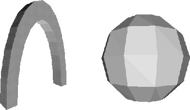
View A in Figure 17.3 shows two brushes before performing a Boolean operation on them. View B shows the union of the two brushes; they haven’t been actually joined but have been merely placed in coincident locations.
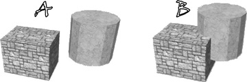
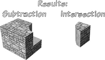
In Figure 17.4 we see on the left the result of a subtraction operation, where the (now removed) cylinder was the subtrahend. We are left with the Cube brush with a “bite” taken out of it, the shape of which matches the part of the cylinder that was previously situated there.
On the right in Figure 17.4 is the result of the intersection operation. You’ll note that all that remains is a brush in the shape of the cubic area that the cube and the cylinder occupied together. With an intersection operation, all solids involved must be selected when the operation is performed.
Now, with Constructor you aren’t limited to only performing CSG operations. You can also shape and distort brushes in various ways by manipulating vertices and faces in ways similar to the more familiar “polysoup” programs like MilkShape and 3D Studio Max.
Figure 17.4
Boolean operation results.
The key here, in using the CSG approach, is that there are limitations and restrictions on the topologies available to us to creating brushes. This is a feature, not a problem. These limitations allow Torque 3D to employ extremely efficient collision detection and rendering operations. The limitations also mean that it is reasonably easy to create software to parse the model and generate the collision hulls (or convex shapes) automatically, eliminating the need for the modeling artist to manually create collision hulls.
TORQUE CONSTRUCTOR
Constructor is a free program from GarageGames, and can be downloaded from their website at www.garagegames.com. Don’t go there yet, though—read on, first. When you get to their main page, near the top under the GarageGames logo, find the link Store. Hover your mouse over it and a menu will appear. Locate Tools and click on it. When the Tools page opens, navigate to the second page using the links below the black button labeled “What Can I Do Here?”. On the second page, about two-thirds of the way down, you will find the Torque Constructor links. You can download from here.
That was the “hard way” to get Constructor. The easy way is simply to go to the companion DVD for this book, and install it from there.
INSTALLING CONSTRUCTOR
There is an installer for Constructor 1.0.3 included on the companion DVD in the TOOLSTORQUEWINDOWS folder. Run the installer, and follow its directions, but I suggest that instead of installing it in its default location (in Program Files) you instead install it to C:Constructor. That’s where I put it; it helps reduce disk browsing.
After you have run the installer, you need to install the update patch, called TorqueConstructor_Update_Win_103-106.zip. Simply extract the contents into your Constructor folder. When done correctly, you will be prompted to allow replacement of various files (the ones being updated) so go ahead and approve all of those prompts.
The update fixes various bugs and adds compatibility with newer versions of Torque 3D.
Once the update is done, you are ready to go.
After you finish you will have Constructor installed into a directory structure that should look something like that in Figure 17.5.
The Cook’s Tour
Let’s have a very quick look at the Constructor interface—enough to be able to talk intelligently about it. Then we’ll get into making something. After that we’ll take another look at some of the other features of the program. So, launch Constructor using your desktop shortcut, or from the Programs menu on your Start button.
Note
With earlier versions of Constructor, when you first ran Constructor, you would be prompted for an ignition key. It should not happen anymore, because one of the updates to Constructor was the removal of the ignition key. If you are prompted for the ignition key, then you should re-install the update.
The Main Screen
When you fire up Constructor, you will be greeted by the pleasing view of the Constructor main screen, as shown in Figure 17.6. Now that just looks like muscle, right there.
Your view of the main screen may vary slightly, depending on your computer’s screen resolution. Figure 17.6 was snapped at 1024 pixels by 768 pixels. If you have higher resolution, you may see more things on your screen, especially in the toolbars on the sides, because Constructor automatically adjusts its contents to suit the available screen real estate.
Figure 17.5
Constructor directory structure.

Resizable Forms
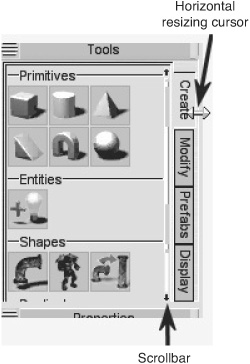
Direct your eyes down into the upper-left corner of the screen, and you will see an area in a box with the label Tools. Oddly enough, this is where you find the tools! Okay, Dave will probably hit me upside the head with a fish for saying that, but in my own defense, I have seen some programs use some fairly strange words when what they really meant to say was “tools.” Anyway, if your screen resolution is fairly low, you might find that the contents of the Tools form are not completely visible, which is the case in Figure 17.7, and as it was in Figure 17.6.
Figure 17.6
The Constructor main screen.

Note the two-way arrow cursor pointing left and right located over the right-side bezel that surrounds the form. Leave that alone for a minute. On the same side of the toolbar is a really teensy, tiny, skinny little twig of a scroll bar. Fortunately, there is a “scroll bar” label there in the figure, with an arrow pointing up to the actual scroll bar. There are two itsy-bitsy, teeny-weeny solid black arrows at each end of the scroll bar. See that? Cute, eh?
Move your cursor over the Tools form, and move your mouse wheel forward and backward. See the scroll bar move and the contents change? Okay, don’t spend too long playing with the wheel. You can also click and drag the “thumb” (the darker part of the scroll bar—the part that slides) up and down instead of using the mouse wheel, or you can click those little arrows.
Figure 17.7
The Tools form with horizontal resizing cursor.
Forms, Palettes, Toolbars, and Tabs…It’s Torque Terminology Time!
Different programs use different words to describe things like the little graphical containers that hold tools, menus, or other visual devices, like the container for Preferences. There is no real standardization in terminology. Some programs call them toolbars, or bars. Some call them palettes. Some, like Paint Shop Pro, use both toolbar and palette and have some features available in one and different features in the other. Some people use the word tab, although that has a more precise, and different, meaning usually. Dave Wyand calls them forms. And if that’s what Dave wants to call them, then that’s what I’m calling them!
Why so small? Real estate. The less screen space the tools take up, the more space there is for your actual model in the view windows, which we will come to later.
Now back to that two-way arrow in Figure 17.7. Just move your cursor to the same location where the two-way arrow is in the figure, and you will see your cursor change to the two-way arrow. Click and drag leftward until you can see as much of the Preferences content as you need, in the horizontal aspect.
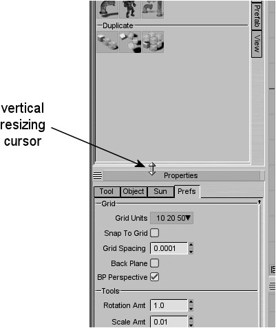
You can do the same thing by “grabbing” the bezel at the top of the toolbar to resize the form in the vertical sense, as shown in Figure 17.8.
Figure 17.8
The Preferences form with vertical resizing cursor.
And yes, in case you are wondering, you can perform all of these same operations on all the forms. That is why we went through this exercise, so that you can get your forms in your Constructor screen to conform to your personal requirements based on your computer configuration. In the next section we’ll briefly go wandering amongst these forms, and while doing that you can go ahead and adjust the sizing of the various forms to suit your fancy.
The Forms
Take a look at Figure 17.9. Notice anything different compared to Figure 17.6? Okay, you Macophiles can stop jumping up and down now! In Figure 17.9 is Constructor shown using the OSX Graphite theme, as might appear on a Macintosh, rather than the Windows-centric Neutral theme that Figure 17.6 uses. I’ve inserted it here to make that point, but also to provide a handy reference for this next part of the tour.
Figure 17.9
The Constructor screen with the OSX Graphite theme.

Starting at the top of the screen, you’ll find the familiar menu bar. It contains a few of the standard menus, like File and Edit, and then a string of specialized menus, culminating with a familiar Help menu. As you click each menu, you will see the familiar drop-down menu. If you choose Layout, Themes, you will see where you can switch between the Macintosh (OSX Graphite) and Windows (Neutral) themes.
The menu bar is the only major visual feature of Constructor that does not have its label out there dangling in the electronic breeze. And I might also point out that it is most assuredly not a form but a menu bar, and I don’t care what Dave says (*smiles and waves at Dave*)!
So, having gotten the menu bar out of the way, let’s proceed on our tour in an orderly fashion. If you would, please step to the far right and upper corner of the screen where you will find the Scene form. In the Scene form you can switch between loaded maps, or between the brushes, entities, static meshes, and reference shapes (yes, shapes!).
Immediately below the Scene form is the Materials form. In this form you can select materials using a browser or a list, switch between texture albums, and perform some materials and texture operations.
On the mid-left side, is the Properties form, where you can find the Perferences. Using the Preferences, you can adjust global program settings like grid values and operations, scene lighting, and so on.
Moving to our right now, we find stretched across the bottom of the window the Selection Modes form. We use this mode to establish what scene objects are chosen when we perform a selection operation in one of the modeling view panes.
Moving back to the left, arriving at the far-left and bottom of the Constructor screen, we encounter the Values form in all its glory. For the moment, the only values reported are the scene coordinates coinciding with the 2D position of the cursor in any one of the view panes. In the 2D views (top, back, right, and so on) only the relevant 2D coordinates are reported. If your cursor is in the Perspective view pane, then the full 3D coordinates are reported in the Values form.
Moving up the left side, we find the Properties form. This is where we set the parameters for the various modeling tools we can use. The contents change according to which tool is currently active.
Finally, above the Properties form, and ending our little tour, is the Tools form. Here we can select various kinds of tools, for creating, modifying, or displaying objects or for using prefab objects, depending on which tab we select. The tabs run down the right side of the Tools form. Within each tab, to varying degrees, is a variety of tools and operations that can be selected, depending on the context.
In the center of the screen, where they refuse to be overlooked, are the four default View forms. Within each of the View forms is a view pane, providing a look into the scene from various angles. At the lower-left corner of each view pane is an axis bug that shows you the orientation of the scene in the view. The blue axis is the Z-axis: positive going up. The red axis is the X-axis: positive going right. And the green axis is the Y-axis: positive going back, or away from the “front,” and deeper into the scene. The lower-right side of each view pane contains a number, in units of meters, that indicates the distance that the view’s camera is from the center of the scene. Along the top of the view pane is a series of buttons that you can use to tweak the way the view works, what view angles are used, and other options.
Now I know that was not a very detailed examination, but the goal was to drag you around the Constructor screen and set the scene, so to speak.
QUICK START
What we’ll do is run Constructor and quickly create a structure that we can stick in our sample Torque game and poke around with. It won’t be anything particularly useful, but the point is to establish mastery of the tool chain. The tool chain is in essence the collection of programs and procedures you need to follow from source creation of a piece of artwork to using a compiled version inside the game engine.
Note
More taxing terminology! In CSG development circles what you create are often called rooms. This hearkens back to early editors for Quake, where everything was a room. There were no outdoor areas as such—no external terrain. When we create the rooms and save them, we save them as map files, because Valve used the word map to describe their version of what id Software (the guys who made Quake) called a room. Clear as mud?
And of course, just to be persnickety, GarageGames calls these creations interiors (which fetches back to the term rooms, in a way) in Torque, and that derives from Torque’s journeyman days as the Tribes engine. I use the word structure, which I think is both pithy and generic at the same time. My use of structure can encompass rooms, maps, and interiors as they are used in their respective contexts while still also applying to things like bridges and guard towers.
Oh yeah, one more thing. In Constructor the entire collection of all the objects you’ve created in one file is called a scene. A scene is a collection of 3D objects, and the word is used in the context of game engines and most 3D shape tools. Constructor uses this terminology because it has the ability to combine CSG objects created in Constructor or other CSG tools, like Hammer, with “polysoup” or mesh objects or shapes created with tools like MilkShape or 3D Studio Max all at the same time! So another word is needed to encompass all of these things. Hence, scene. When we save our scene, we can save it as a map file (I tossed this in just in case you might be thinking that you finally understand everything).
So scene = room = map = interior = structure. Sort of, sometimes. In any event, the source format for the files we will be dealing with are MAP, a text file format, while the compiled version is called DIF, a binary format.
We save our work as .csx files—this is called the native format for Constructor creations—and compile the work to .dif for use in Torque 3D using the Export As DIF function. More about this later.
We can also save our work as Valve 2.0 compatible files in MAP format. See the sidebar, “CSX vs. MAP.”
CSX vs. MAP
Using CSX format files, we can save information about scenes that MAP format files don’t support and wouldn’t understand, like the placement of references shapes as static meshes and various other features, as shown here:
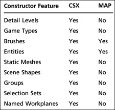
So why use MAP format? Well, there are dozens of tools out there that support MAP format in addition to Constructor—Valve Hammer, 3D World Studio, Quake 3’s tools, to name but a few. It’s fairly ubiquitous, but somewhat limited. If you are new to all this, use the native CSX format.
1. If Constructor is not running, launch it now.
2. Locate the Tools form in the upper-left corner and, within it, the Cube brush in the Primitives section, as shown in Figure 17.10.
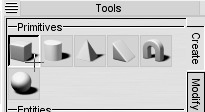
3. Click the Cube brush to select it. The brush icon and the cursor will change, as shown in Figure 17.11.
4. Move the cursor over to the Top view pane, positioning it four grid squares left and four grid squares up from the center (where the heavy dark grid lines meet).
Figure 17.10
About to select the Cube brush.
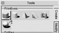
Figure 17.11
The selected Cube brush.
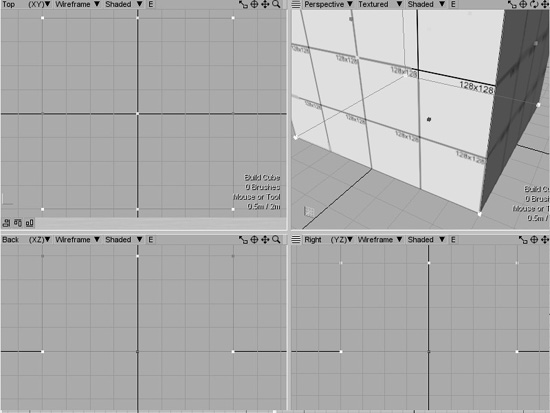
5. Click the mouse button, drag down and to the right until you are positioned four grid squares below and four squares to the right of the center (as shown in Figure 17.12), and then release the mouse button.
Note the small red object handles on the left and right sides, and the small green handles on the top and bottom sides (which, when in the Top view, are actually the front and back sides of the object, as oriented in the scene). You can grab these handles and resize the object in this view, or any of the other 2D views, without having committed the brush to the scene. In other words, we only have a “phantom” brush object at the moment.
Figure 17.12
After click-dragging from upper left to lower right.
6. Press the Enter key to commit the brush to the scene. Note the change in appearance of the cube.
The handles have now disappeared, and colored arrows sprout from the center of the object. Collectively these three arrows are called the Axis Gizmo. Each arrow points along an axis in the positive direction. The red arrow is for the X-axis, green for the Y-axis, and blue for the Z-axis. You can also see the little axis labels at the end of each arrow. The gizmo not only shows the axes and their orientation but also serves as the “grab handle” for different transformation operations, as we’ll see shortly. Figure 17.13 shows the new appearance of the cube object.
While we’re at it, we ought to do something about the awful texture we’re stuck with, created for us by default.
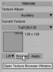
7. Cast your eyes over to the right-hand side, into the Materials form. That perfectly horrid texture is there, glaring at us in yellow and blue. Just below the texture, locate the Browse button, as shown in Figure 17.14. Click it, and watch the Texture Browser dialog box appear.
Figure 17.13
Cube after being committed to the scene.
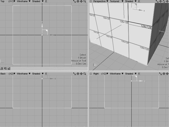
Figure 17.14
The Browse button.
Note
“That perfectly horrid texture is there. What’s up with that? Is this the Texture Taste Police?”
I actually heard you say that out loud, you know (*waggles index finger*).

Yeah, that one. All yellow and blue with “Error” written all over it and stuff. Well, note that it’s the default texture. Unless you choose a different texture (the procedure for which is covered just a little bit later in this section), then every time you create an object in the scene, it will have this texture assigned to all faces. There is a good reason for this.
The usual way most modelers create structures using CSG tools is to first create the structure and then apply the textures when the structure is finished and the artist is happy with the result. In other programs often the null texture is assigned as the default texture. The only problem is that the null texture doesn’t show in the game engine. The face will be completely transparent, since there is not actually a texture present (it was null, see?). If you forget to assign a proper texture to a face, you might have a lot of difficulty detecting this visually. At various angles you might see a background texture behind the face with the null texture and not realize that the texture is missing. And yet from another angle that hole where the texture is missing might provide a view into or out of an area that would interfere with game play in a serious way.
By using such a garish default texture, if you were to miss out on texturing a face and then went into the game to visually verify your model, you would have a much better chance of detecting your error.
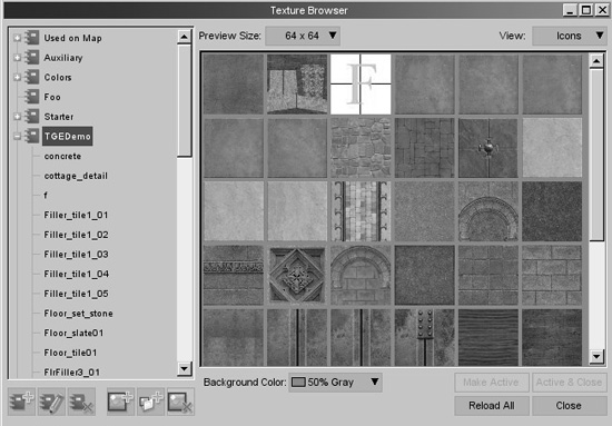
8. On the left side of the Texture Browser, select the entry (or album), TGEDemo, by clicking it. Figure 17.15 shows what this looks like.
Figure 17.15
Texture Browser with TGEDemo selected.
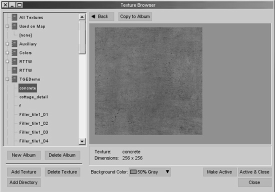
9. Click the first texture in the upper-left corner of the texture array (concrete) in the Texture Browser. The contents of the browser change, focusing on the texture you chose, as shown in Figure 17.16.
10. At the lower-right corner of the Texture Browser resides the Active & Close button. Click it. The Texture Browser will close.
11. Back over in the Materials form on the right, locate and click the Apply button, just below the little picture of the texture you just selected. Take a look in the Perspective view pane at the upper right. You will see the cube with the new texture applied to it, on all faces.
Tip
If you find yourself stuck in some mode that you don’t want to be in, press the Escape key. This will allow you to go and select things again, or change your modes, or whatever. There’s a reason why it’s called “Escape”!
This won’t work as well if you are in a dialog box, however. But then, you have to try harder to get stuck into an unknown mode while in a dialog box.
Figure 17.16
Texture Browser with the concrete texture.
12. Now we have to export our scene. Go to the File menu, and choose Save As. The Save As dialog box will open.
13. Save your work as test.csx in the scenes folder that’s inside the Constructor folder.
14. Choose File, Export As DIF….You will get a dialog titled Export As DIF.
15. Do what the dialog title tells you, and browse your way to the 3D3E DemoExamplesFPS Examplegameart folder. You need to create a folder in here called “interiors”, so go ahead and do that and then double-click on the interiors folder to browse into it. Click on the Save button. You will then get a rapidly changing progress dialog showing the export process underway. You will know you have successfully exported the structure as test.dif when the dialog vanishes and there are no error messages.
16. Now go launch your Torque demo, as you’ve done in the past, and choose the Deathball Desert level.
17. After you’ve spawned in, switch to camera fly mode (F8), go up a little bit in altitude, and aim your cursor to a point in the game world where you want the test structure to be. A good place to go would be over one of the “stations” that have the bridge between the two towers. Park yourself on top of one of the towers. Then aim the center of your screen to the open area to the side of the tower.
18. Open the World Editor by pressing F11. Because the demo is limited in the number of objects you can put into the scene (there is a way around this, by the way. I might tell you later, if you are nice), you need to delete some objects to make room for your addition.
19. Press F1 to get the Object Editor, and then in the Scene tab in the Scene tree panel over on the right side, expand the MissionGroup entry by clicking on the little triangle to the left of the MissionGroup entry.
20. Locate and expand the Structures Simgroup, and in there, delete one of the folders—Orange or Green. It doesn’t matter which. Now you have some room for your stuff.
21. Now change from the Scene tab to the Library tab on the right side. In there, locate the Meshes sub-tab and click on it once to open it. Find the art folder, double-click it, and you will find the interiors folder we made earlier. Open that and you find the DIF file we created.
22. Double-click on the test entry in the interiors list. Your creation will be plunked down at the spot where the center of your screen intersects a point a certain fixed difference from the camera. If you haven’t yet made room for your model (see step 19) then you will get a dialog telling you that you can only have 32 objects in your scene. Go back to step 19, and do it right this time!
Tip
You can relight the scene at any time while in the Mission Editor by pressing Alt+L or by choosing the Lighting, Full Relight menu. In fact, you can easily make your textures appear on your structures just by grabbing them and dragging them a bit. But the scene might still need relighting, if the shadows need to be re-baked.
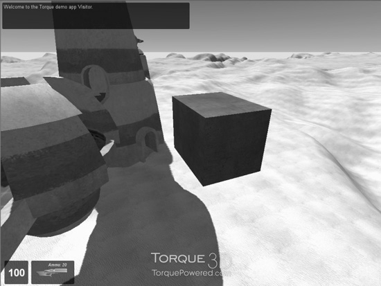
You should have ended up with something like what you see in Figure 17.17. Of course, where the cube actually is depends upon where you decided to plunk it.
That took a while, but what we’ve done, in addition to learning the basic steps involved in getting a structure exported in Torque, is to prove the tool chain. We now know that we have all the required bits and pieces to get this kind of artwork into the engine. The CSG tool (Constructor), with its built-in exporter, and, of course, the in-game Torque World Editor. This might seem trivial, but proving the tool chain is an important first step in any project involving multiple programs and processing steps.
Figure 17.17
Cube test object in the demo game.
Managing Your Textures
When you make a model with Constructor, no doubt you will be using textures on the faces. You need to ensure that you copy the textures from whatever folder they are contained in to the folder in the Torque path where they will be needed.
The textures we will be using in this chapter are in the Constructor extures gedemo folder. If the textures aren’t already in the interiors folder where we deposit the DIF file, Constructor automatically copies them for you. So you only need to keep the source of your textures up-to-date. The destination is synchronized seamlessly.
Constructor also generates a text file alongside the DIF file that contains reference information about the model. The most useful information is a list of all the textures used by the model. This greatly aids in figuring out what’s missing if a texture doesn’t properly show in the game. If an expected texture isn’t in the list in the text file, then it didn’t get exported. If it didn’t get exported, it probably isn’t in the source .csx file.
BUILDING BRIDGES
So, you’ve had a taste of how you can use Constructor. Now let’s dive in and muck about with it a bit and actually create something. Because this is our first real structure, we’ll start out with something not too complex—a stone bridge.
1. Launch Constructor.
2. Select the Cube brush.
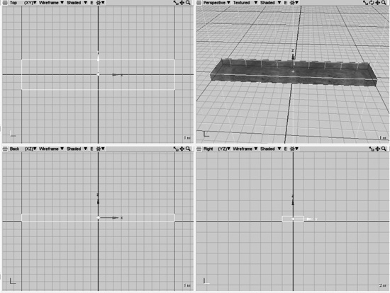
3. In the Top view, create an Oblong brush that is 4 units (grid squares) wide in the Y-axis, and 20 units long in the X-axis.
4. In the Front view use the little blue handle to move the bottom or the top edge (doesn’t matter which) until the shape is only 1 unit high in the Z-axis. Then, if needed, continue to use the red, green, or blue handles to resize the brush where needed, and the little light-blue handle in the center of the brush to move it until you have something resembling Figure 17.18. This is the roadbed of the bridge.
5. Press the Enter key to commit the brush when you are satisfied with your handiwork.
Tip
You might find it difficult to move or otherwise modify a brush before it is committed, because the hotspots where you can grab the brush to make the changes are very persnickety before the brush has been committed. Take heart! You can go ahead a commit a brush as soon as you’ve created it, and then make the adjustments afterward.
Tip
If you want to check the dimensions of your brushes, just position your cursor over the boundary lines at appropriate places, and look in the Values form at the lower left. Your cursor’s coordinates in the window where the cursor is located will be shown. Remember that if the center of your brush is at the same location as the center of the scene, then boundary values for your brush will show as exactly half of the dimension being checked.
For example, if we want the Oblong brush to be 20 units long, then when you place your cursor over one end of the brush in the Top view pane, the X value will be 10.000.
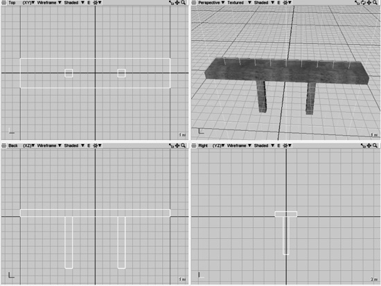
6. Create two more Cube brushes, and place them as shown in Figure 17.19. These will be the bridge pylons.
Tip
While in brushes selection mode, you can create a copy of a brush simply by selecting a brush, holding down the Shift key, clicking on one of the axis arrows for the brush, and then dragging in the direction of the axis arrow. A copy of the selected brush will be dragged away from the original. Make sure that you are in brushes selection mode when you do this.
Next, we are going to add some texture to the bridge.
Tip
If you have the texture you want selected when you create a brush, then the brush will automatically receive that texture on all of its faces when you commit the brush to the scene.
7. Ensure that the Brushes button is depressed in the Selection Modes form at the bottom of your window, and then move your cursor to the Perspective view pane.
8. Click your cursor inside the Roadbed brush to select that brush.
9. In the Materials form at the right, click Browse to invoke the Texture Browser.
Figure 17.19
Bridge with pylons.
10. Click the texture album called TGEDemo to select it.
11. Locate and select the Floor_set_stone texture.
12. Click the Active & Close button, to make the texture active, and close the dialog all at once.
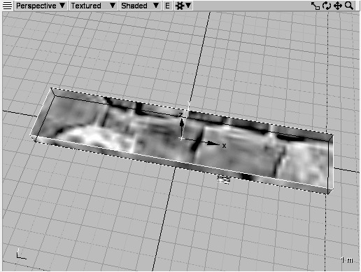
13. You will see that the texture has been applied to the brush already, because we had the brush selected when we clicked the Active & Close button in the dialog. If the brush was not selected, we would have to select it. Back in the Materials form, click the Apply button. Check the Perspective view pane for evidence of success. You will see the cube with the new texture applied to it, on all faces, as shown in Figure 17.20.
Notice that the texture seems really big and a bit blurry. Now we have to adjust the scale of the texture. This is a bit of a fiddly operation. By eyeball, I estimate that the texture is about four times too big. So we need to make the texture about 25% (or 0.25) its current size.
Figure 17.20
Roadbed with Floor_set_stone texture.
14. In the Selection Modes form at the bottom, click the Faces button.
15. In the Perspective window, click one of the faces of the Roadbed brush. It will be highlighted as shown in Figure 17.21. It’s pretty hard to see the color effect in that grayscale image—the highlighted face will have an aquamarine or green hue to it. Also note that a small cubelike device appears that shows the orientation of the applied texture. In Figure 17.21 the selected face is the top face.
16. Look over to the left side in the Properties form, and click on the Object button near the top of the form. You will see a set of texture mapping (or UV mapping) tools appear in various panes. There is a pane called Texture Position.
17. In the Texture Position pane of the Properties form, locate the Scale fields. In each field (X and Y) type in 0.25. Be sure to include the zero in front of the decimal.
18. Press the Enter key. You should now have a brush face that looks like Figure 17.22.
Figure 17.21
Selected brush face.
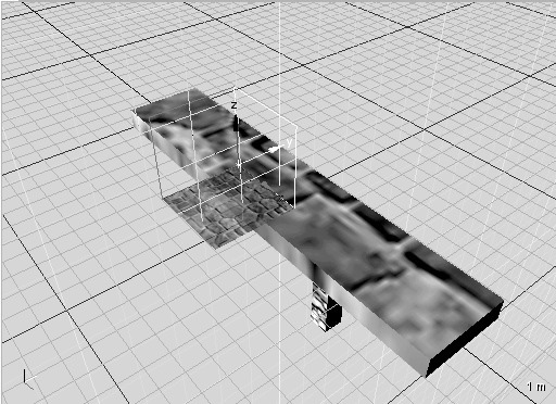
Figure 17.22
Scaled face texture.
You can rotate and move (offset) a texture using the same technique on the other fields labeled appropriately.
19. Now go ahead and apply textures and adjust them as you want, for all the other faces.
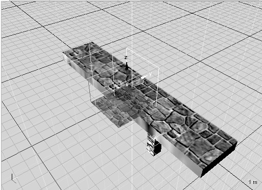
20. Save your scene as bridge.csx in the Constructorscenes folder, and then choose File, Export As DIF…to export your bridge to Torque 3D, just like you did in the last section.
21. Now go launch your Torque demo, as you’ve done before. After spawning, switch to camera fly mode (F8), go up a little bit in altitude, and aim your cursor to a point in the game world where you want the bridge structure to be.
22. Open the World Editor by pressing F11.
23. Open the Object Creator by pressing F1 (it’s probably already open, but you know…).
24. Find your way to the Interiors folder in the Meshes pane inside the Library tab Then drill down through art, and interiors, and you will see bridge listed.
25. Double-click on the bridge entry in the Interiors list to insert the bridge.
BUILDING A HOUSE
The bridge was nice and certainly useful albeit fairly simple to execute. If you actually need a bridge you will probably make something more ornate. The point here is to learn the tools. Artistry is up to you.
In this section we will go a little bit further and make something a bit more complex: a hut with a door opening and a window created using CSG Boolean operations.
1. Launch Constructor.
2. Select the Cube brush, and create a cube that measures eight units in length (along the X-axis) by six units in width (along the Y-axis) by seven units in height (along the Z-axis).
Remember that you can check the dimensions by hovering the cursor over various points on the cube and looking in the Values form at the lower-left corner of the Map Editor window.
3. Position the Cube brush so that it is horizontally centered in the Top and Back views and vertically offset upward in the Back and Right views so that two units are below the centerline and five units are above it. See Figure 17.23 for guidance.
Figure 17.23
Properly sized and positioned initial brush.
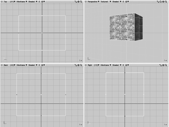
The brush is offset vertically so that the centerline can be used to represent ground level. Because this is going to be a building that might be placed in somewhat rough terrain, we need to make sure to have a “foundation” or “basement” that extends fairly far below the ground level. Although I am not doing so here, you might consider using a separate brush for the basement, so that you could use a texture different from the aboveground textures. A nice concrete texture would be suitable.
4. Don’t forget to press Enter to commit the brush to the scene.
It’s important to remember that there are several selection modes: Brushes, Faces, Edges, and Vertices. The buttons are at the bottom of the screen. Make sure you are in the selection mode you need for the operation you want to perform. A handy keyboard shortcut is to press 1 for the Vertex mode, 2 for the Face mode, and 3 for the Brush mode.
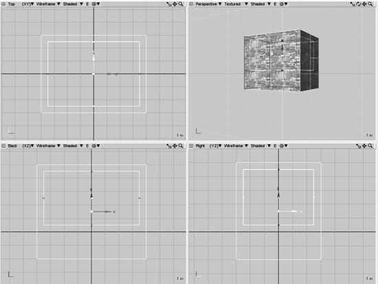
5. Next, go back and select the Cube brush tool again, and make another brush inside the first one, except make this new oblong seven units in length by five units in width by four units in height.
6. Position the new brush so that it is centered horizontally inside the first brush and positioned vertically aboveground so that it is centered between the top of the first brush and the ground level. Figure 17.24 shows what this should look like.
Figure 17.24
New brush inside the first brush.
7. Commit the brush to the scene. The new brush will remain selected, and that’s what we want for the next step.
Tip
Just a quick reminder: if you find yourself stuck in some mode that you don’t want to be in, press the Escape key.
8. In the Tools form on the left there are tabs whose labels are displayed sideways down the right-hand side of the Tools form. Click the Modify tab.
9. In the CSG group of iconified buttons that now appear in the Tools form, the one on the far left is the button for the Boolean Subtract operation. Click that button. This will subtract the volume of the second brush from the first brush. You will notice a subtle change in the 2D and Perspective views after you’ve pressed the Boolean Subtract button. There will be some extra lines. The second brush is still selected.
Tip
When you’ve performed a Boolean CSG operation on a brush, the brush will be transected into multiple different brushes which together make the resultant brush. You can select each of these sub-brushes and treat them like normal brushes, because in actuality, they are just normal brushes.
10. Press Delete. The second brush will be removed. It might not be obvious, but your first brush is now hollow, and it should look like what’s shown in Figure 17.25.
You may find it helpful to immediately group the brushes in the resultant object together so that you can still treat it like a single brush. Select all of the brushes in the resultant object, and then choose Objects, Group (or press Control-G).
11. Back in the Tools form, click the Create tab on the right-hand side of the form (with the label written sideways).
12. Select the Cube brush yet again. (Are you getting the feeling that you will become intimately familiar with the Cube brush in fairly short order?)
Tip
Don’t get too focused on working in only one view. Sometimes everything needs to be done in a single view, but you should glance in the other views to monitor your progress and to ensure that you aren’t doing something really dumb that isn’t visible in the view you are working with.

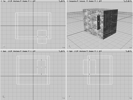
13. Make a brush for the door that is two units long, three units deep, and three units high. Position it so that the bottom is level with the “floor” and so that it protrudes from inside the hollow brush to the outside, as shown in Figure 17.26. Commit the brush.
14. Now click the Modify tab again, in the Tools form, and then click the Boolean Subtract button (far left) once more. This will carve out the door.
15. This time, don’t delete the Subtraction brush. Instead, grab that sucker by its X-axis gizmo in the Back view, drag it left, and then drag it up using the Z-axis gizmo. We can reuse this brush (it’s the Earth Day thing to do!) to make a nice little window. Drag it around in the Back view until it’s positioned to the left of the door and suitably up from the floor.
Figure 17.26
Protruding Door brush.
16. In the Tools form, in the Transforms section, click the fourth button from the left—that’s the Size Bounds button. Doing this in the Tools form is exactly the same as choosing the Tools, Modify, Scale menu.
Tip
The Planer Scale button is the same as Tools, Modify, Scale option, and the Size Bounds button is the same as the Tools, Modify, Size option.
17. Move your cursor directly over the center of the Subtraction brush in the Back view, then click and drag your cursor to resize the window to your liking, using Figure 17.27 as a guide.
To quickly go back to the mode where you can move objects around by clicking them and dragging (translating), just press the Escape key.
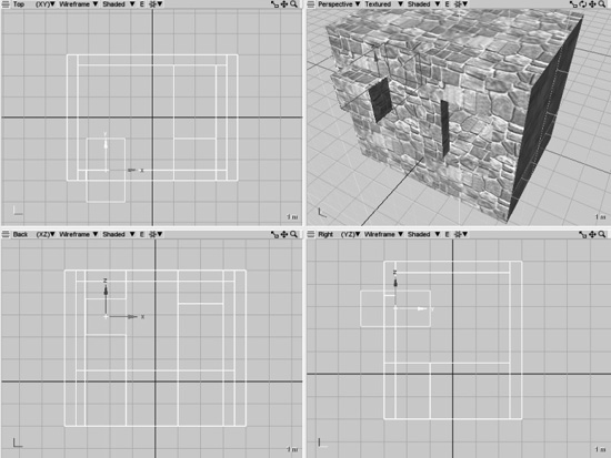
18. Once you are happy with the position of the Subtraction brush, press the Boolean Subtract button again. This will carve out the window.
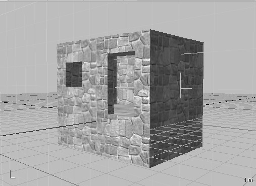
19. Press Delete to remove the Subtraction brush. Now you will have a handy one-room house, as shown in Figure 17.28.
Note that I’ve used the Floor_set_stone texture for all of these brushes. You, of course, have been empowered and are free to use whatever textures you want!
20. Save your file as Constructorsceneshouse.csx.
Okay, export your house, using the technique I showed you earlier. As an extra challenge, export your house for use in the Emaga6 program. Go ahead, I dare you! Good luck!
Figure 17.28
House with door and window.
MOVING RIGHT ALONG
So, in this chapter you learned yet another tool. Constructor is a pretty feature-complete tool for creating structures for Torque. You built the two most common sorts of structures: an outdoor structure (the bridge) and a building using CSG operations.
Your imagination is the only real limit here. Castles, complex underground tunnel systems, factories, playgrounds, and just about anything else can be created with Constructor.
In the next chapter we’ll take a look at how to make things for the game world environment.