CHAPTER 14
MAKING A CHARACTER MODEL
In this chapter we are going to build a character model, step-by-step. We are going to animate it and skin it. It’s going to be a long and sometimes hectic ride, so hang on to your hat! For example, my wife took about 30 hours, spread over almost a week, to work through this chapter.
Oh yes, and remember—the more time you spend on your modeling and artwork, the better your final product will look.
MODELING TECHNIQUES
Modelers use many different approaches or techniques. The differences can be based on what tools are available to do a given job or what data is available about the item to be modeled. Other techniques are available but not described here—that’s because we are modeling for games, and low-poly modeling is the philosophy we need to follow. Remember that the more polygons one model uses, the fewer polygons available for other instances of that model, or for other models, in a given rendered frame of a scene at a given frame rate. In games there is that polygon budget to consider.
Note
In this chapter we will be using FPS Example, so your game folder will be 3D3EDEMODemosExamplesFPS Examplegame.
Shape Primitives
In two dimensions, primitives are the simplest geometric constructions: dots or points, lines, rectangles, ovals or circles, arcs and other curves. We can assemble all other more complex shapes using these basic or “primitive” 2D shapes.
In three dimensions, the primitives are: planes or faces, boxes, cylinders, spheres, pyramids or prisms or wedges, cones, and arches. When we talk about shapes in three dimensions, we typically mean a fully enclosed collection of faces that simulate some real-world solid object. So, while planes and faces are certainly 3D primitives, they are not normally included in the list of 3D shape primitives.
Creating models using shape primitives can be an extremely quick way to build a low-poly model, depending on your expertise and eye for detail. The basic technique involves selecting a primitive that best matches the part of the model you are building. The primitive shape must contain enough polygons and vertices for you to adjust the shape to closely match your target.
This is the technique we are going to use to build our character model in this chapter.
Box Method
This is a variation of the Shape Primitives method, whereby we start out with a box primitive and then subdivide the faces of the box into smaller faces based on our needs for more detail in the model as the model takes shape. As we subdivide each face, we yield more polygons that can be moved around and placed. More detail means more faces, and more smoothness means more faces. When making a head, we might start with a simple box with six faces and end up with a complex shape with more than a hundred faces.
Incremental Polygon Construction
Incremental Polygon Construction is a method that fairly closely approximates modeling with clay in the real world. Sculpting with clay generally involves adding bits of clay together to create shapes that grow in size and detail. The clay can be poked and prodded, smoothed and pinched, until it accurately depicts the item being modeled.
With Incremental Polygon Construction, the process is similar. We apply vertices in 3D space that represent high points and low points of the features to be modeled, and then we build triangles or faces connecting these vertices. One point of departure from clay modeling is that we typically don’t add faces on top of (such that they completely obscure) other faces, because we have no need for a solid to give us the required volume. But the principle of adding faces to the existing topology of a model as the model grows is the same, as is the useful concept that we add only what we need and no more.
The best way to get started with modeling in this way is to use photographs or sketches of the target from several directions: from directly in front, directly above, and one or both sides. From the pictures we can obtain the locations and shapes of the features and their high and low points. We mark these points in our 3D views, and then we proceed to build faces from them.
This technique can be quite slow going. It is also prone to errors that are difficult to correct, because you may have moved dozens of steps beyond where the error actually occurred before the error becomes evident.
Axial Extrusion
In the simplest sense, you start with a primitive object (usually a box, but it could be a simple facet or triangle), subdivide it, and then select specific polygons to extrude into meshes to form general shapes. When you subdivide objects, you increase the number of polygons on each side of the shape. You then adjust and refine the extruded polygons to form the details of the model. This approach is similar to making models of geographic terrain using a contour map as a guide, with cardboard or plywood sheets to build up the terrain, and then smoothing the edges with some kind of filler.
With Axial Extrusion, you limit your extrusions to one of the three axes—sometimes all three in various combinations—but individual extrusion only occurs in one axis. This technique is usually restricted to inanimate objects, but sometimes certain parts of character models are made this way.
One example of using axial intrusion in character modeling is when creating a head. A series of flat-plane profiles (called cuts) are made of a head, after which each profile is extruded once in each direction on the transverse axis (the axis that runs from ear to ear). Then each extruded mesh is married to the extruded meshes of the adjacent cuts by an averaging of the vertices. You’ll actually get to do some of these extrusions later in this chapter and others.
Arbitrary Extrusion
Arbitrary Extrusion has much in common with Axial Extrusion, except that you extrude your base primitive shapes in whatever directions are necessary. Like Incremental Polygon Construction, this approach to modeling can be seen as similar to sculpting in clay. Machinery lends itself well to modeling with this technique.
Topographical Shape Mapping
Topographical Shape Mapping is a method usually used to model terrain, like Axial Extrusion often is, except that Topographical Shape Mapping is best suited for automated operations rather than manual modeling.
In the geographic sense, topographic data can be obtained from various government and private sources. The data consists of, at a minimum, a coordinate and an altitude for each mapped point on the real terrain’s surface. Various algorithms and many programs that can read this data from a file and render a 3D view of the terrain in question are available. The data files come in various formats depending on the agency that produces them: DLG-O, DEM, SDTS, and DRG, to name just a few from that acronymic world. Normally, this approach is used in one of the many available Geographic Information Systems (GIS), and there are tools that can convert this data into a format you can use for modeling in games.
Hybrids
Well, the Hybrid category is the catchall category. Often it is prudent to combine techniques in a single model—use the approach that works best for the component being created. If you find yourself mixing techniques, most likely you will be doing a little bit of Incremental Polygon Construction mixed with many shape primitives or using a few primitives mixed with a great deal of Arbitrary Extrusion.
The best point to be made here is that you should use what works best for you in your current circumstances.
MODELING FOR TORQUE 3D
When we create models that we want to export for use in Torque 3D, there are a few (but not many) rules that must be followed. The aspect of modeling for Torque 3D that has the most impact is supporting Torque 3D’s animation scheme. At the simplest level, Torque 3D has built-in support for using certain animations at certain times. You merely need to create the animation sequence in one of two ways (which I’ll tell you about in a minute), name the sequence appropriately, export the animation, place the model with (or without, depending on the method used) its animation in the appropriate place in the Torque 3D folder tree, and proceed. This little process—from creating the model to using it in a game—including the tools used to execute the steps in the process, is called the modeling tool chain.
Torque 3D supports animations in two ways that are covered in this book. The first way is to use embedded animations, where the animations are included with the model in the DTS file. The second method is the DSQ or Torque 3D Blended Animation Sequence system, which itself has two important features: it supports blended animation, where two different animations are played for the same model at the same time, and it supports the separation of animation sequences from the model (DTS) using the sequence files (DSQ) format.
Using either method, you can create your own skeleton with your own bone-, joint-, or node-naming system, or you can use the Torque 3D Blended Animation Sequence system. The caveats are (1) you need to use the Torque 3D Blended Animation Sequence system if you want to play more than one animation sequence at a time, (2) if you want to employ the animations provided by Torque with the Torque 3D demo that employ the Torque 3D Blended Animation Sequence system, you will need to use a bone-, joint-, or node-naming convention that matches theirs, and finally, (3) you need to use DTSPlus Exporter (by Chris Robertson), which exports sequence files (DSQ). And why not use GarageGames’s animation sequences? There are about three dozen animations already done for you! You would then only need to create animation sequences that fulfill your specific needs and use the stock sequences for everything else.
Anyway, even if you do not use the Torque 3D Blended Animation Sequence system but want to use the embedded animation approach, you will still need to make sure that you name your animations properly if you want Torque 3D to automatically invoke them for you.
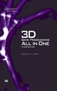
Table 14.1 (found later in this chapter) has a pretty comprehensive list of animations that Torque 3D will recognize by name, along with the contexts in which they are used. Here is a list of the most common character animations:
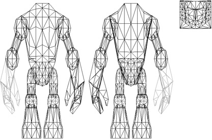
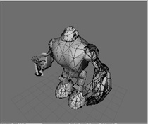
THE BASE HERO MODEL
But first, we need to create a character model. The technique we are going to use is basically the Shape Primitives approach. We will hand-modify various shape primitives to get the results we want.
The kind of model we are going to make is primarily a segmented-mesh model. An alternative would be a continuous-mesh model. The difference is that in the segmented-mesh model, there are different, distinct objects or meshes for different components in the model, whereas in the continuous-mesh model, the entire model has one large, convoluted surface. Our primary segments will be as follows:
![]() head
head
![]() torso
torso
![]() right leg
right leg
![]() left leg
left leg
![]() right arm
right arm
![]() left arm
left arm
So that’s six segments in all. (A continuous-mesh model would have one segment.) All the leg and arm segments will each have two subsegments. Each segment or subsegment can be thought of as an individual mesh, or submesh.
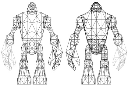
To get an idea of what the finished model will look like, flip ahead a bunch of pages and take a peek at Figure 14.63, “The completed Hero model.” I’d insert that picture here too, but I don’t want you to have too many preconceived notions about what it should look like. The point of this chapter is to learn techniques and procedures, not be a human photocopier (not that there’s anything wrong with that)!
The Head
This would be a good time for you to do a little bit of setup for MilkShape 3D. Select File, Preferences and then click the Misc tab. Change the Joint Size from the default of 1.0 to 0.05 and then click OK. We do this in order to set a usual visual appearance for the joints. With the Joint Size set to 1.0, the joints of the models included in RESOURCESCH14 would be much too large and will result in an image that looks like it has been scribbled on by a two-year old. We’re not going to encounter the joints until much later in the chapter but best to get this done now.
We’ll use the Shape Primitives approach to build the head. The keys to successful use of this technique are (1) choosing the right primitive and (2) using a primitive with sufficient vertices to do the job.
For the head part of the model, we’re going to use a cylinder with 12 faces on the tube, stacked 6 segments high. That translates to a 6-stack, 12-slice cylinder, in Milk-Shape 3D terms.
Tip
Makes sure to set up your views to match mine. Right-click in each view, and from the Projection submenu, choose the appropriate projection for each view:
The Top-right view should be set to Projection, Left
The Top-left view should be set to Projection, Front
The Bottom-right view should be set to Projection, 3D
The Bottom-left view should be set to Projection, Top
1. Open MilkShape 3D, create a new document, and in the Preferences dialog box, set Point Size to 3 and Grid to 1×1 in the Preferences dialog box. Save the new file as in your game folder under artshapesactorshero. You’ll have to create the hero directory.
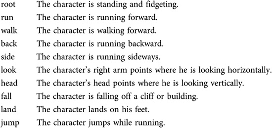
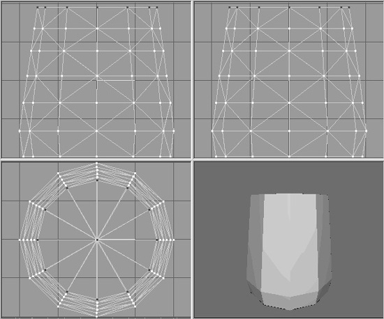
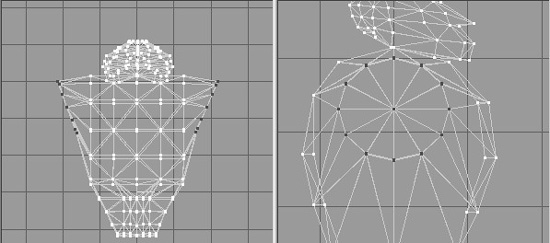
2. Create a 6-stack, 12-slice cylinder, as depicted in Figure 14.1. Size the cylinder such that the bounds of the cylinder extend from about −20 to +20 on all three of the axes.
Figure 14.1
The initial cylinder.
3. Choose Select in Vertex mode, and from the Side view (right pane), select the bottom layer of vertices. Ensure that both the Redraw All Viewports and Auto Tool boxes are checked.
4. Scale the selected bottom vertices to 95 percent of original (on the X- and Z-axes, ensure that the Y-axis scale value is 1), as depicted in Figure 14.2. Make sure that the Scale Options has the Center of Mass radio button checked.
Figure 14.2
Selecting the bottom vertices.
Tip
To turn off the grid display in any view, right-click in that view and choose Wireframe Overlay to uncheck that menu item.
5. Now select the top five rows of vertices, ignoring the bottom two rows, and scale them to 95 percent.
6. Next, scale the top four rows of vertices to 95 percent.
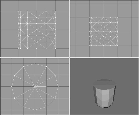
7. Repeat the scaling operation for the top three, then the top two, and finally the top row by itself. You should now have a cylinder with a bit of a bevel at the bottom that tapers gently toward the top, as shown in Figure 14.3.
Figure 14.3
Tapering the cylinder.
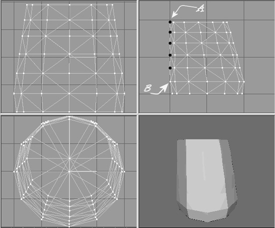
8. Next, shift the top five layers of the cylinder toward the back, so that the rearmost vertices (designated A, highlighted in black, in Figure 14.4) line up, at the back, with the layer of vertices that is second from the bottom (B in Figure 14.4). They don’t have to be aligned precisely, but try to get them pretty close, as shown in Figure 14.4. You can cycle between Select and Move for each layer to move the layers one at a time.
9. Next, working from the Right view (Top-right viewport), select the bottom six vertices visible in that view (at the right side of the view), and move them down and to the right a bit. Figure 14.5 shows which vertices you want and how far to move them. These vertices make up the jaw.
10. Select all the vertices in the model, and scale to 75 percent in the Y-axis only. Do this by typing the value 0.75 into the Y scale box when you have the Scale tool selected and then clicking Scale. Set the X and Y scale values to 1. Don’t forget to save!
Figure 14.4
Shifting the layers.
The view in what MilkShape calls the Left viewport is for us actually the Right view (or Right Side view), located in the upper-right frame, because Torque 3D’s coordinate system is oriented differently. It’s because of this that I normally use MilkShape 3D with the Show Viewport Caption option under the Window menu turned off, in order to avoid confusing myself.
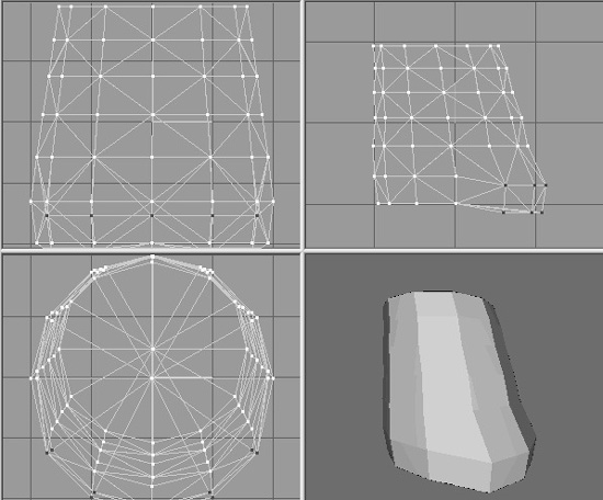
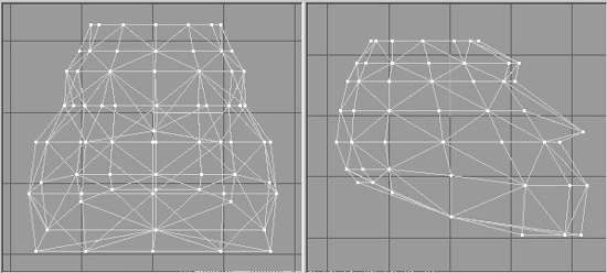
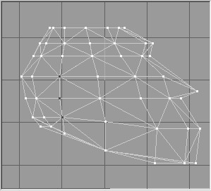
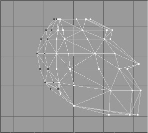
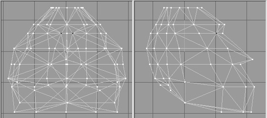
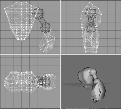
11. Now, using the same technique of selecting and moving (without doing any scaling) as explained in steps 4 to 9, shape the model as near as you can get to Figure 14.6. This is the Right Side view (upper-right frame). You only need to work in this view for now, and no other, and you only need to use the Select and Move tools. Now you can see the head shape taking form in profile, with the nose jutting out.
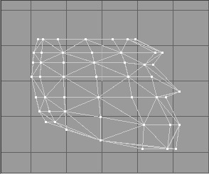
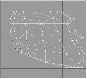
12. Okay, this next part gets a bit tricky. Using the Right Side view, select the 16 vertices in the lower-left corner (which is the lower back of the head/upper rear neck area), as shown in Figure 14.7.
13. Scale this group of vertices to 80 percent by typing 0.8 in the X-axis scale box, and then clicking Scale.
14. Now select just the nine vertices in the lower left, as shown in Figure 14.8, and scale these to 80 percent again.
What this does is make the jaw and cranium parts of the head stand out in an exaggerated fashion. By doing the scaling incrementally on the vertices in the region like that, we get a fairly smooth shape. Take a moment to swivel the model around in the 3D view, and you can now see a definite cartoonlike big-jawed, low-browed heroic figure taking shape. Okay, so not all heroes look like that. But we’re making a game, right? So make it fun!
Figure 14.7
Back of the head/upper neck.
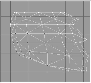
Figure 14.8
The smaller back of the head area.
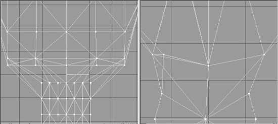
Now, as cute and lovable as that beetle-browed look is, it’s a bit too Cro-Magnon and robotic looking, so we need to tone down the forehead and eyebrow area somewhat.
15. In the Right Side view, in the row of vertices that is second from the top (see Figure 14.9), select the vertex that is the second from the right (in the temple area) by dragging the Selection tool around it. This will have the effect of selecting that vertex and any others that are obscured behind it. There happens to be one more back there, so you will end up with two vertices selected, which you can see by examining the model in other views.
Figure 14.9
The temple vertices.
16. Drag the vertices back (to the left) a few ticks.
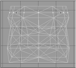
17. Switching now to the Front view (upper-left frame), scale those two vertices by 120 percent in the X-axis. This has the effect of widening the gap between them. (See Figure 14.10.) These steps have the effect of softening the sharp corners, just enough to make the head more organic looking.
Figure 14.10
Scaling the temple vertices.
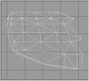
18. Still with the Front view, select all the vertices in the top three rows, which is mostly the cranium area, and then incrementally apply 90 percent X-axis and Z-axis scaling to them—as you did earlier: top three, then top two, and so on. Figure 14.11 shows the results we are looking for here.
Figure 14.11
Scaling the cranium.
19. If you haven’t saved your work recently, do it now. No particular reason, other than it’s good practice to save periodically. We’re getting close to being finished with the head.
20. Using Figure 14.12 as a guide, select the three ear vertices in the Right Side view.
21. Stretch the ear vertices apart by scaling them 117 percent in the X-axis, as shown in Figure 14.13.
22. Now still in the Right Side view, guided by Figure 14.14, select the three columns of vertices at the rear of the head.
Figure 14.13
The scaled ear vertices.
Figure 14.14
Selecting the three columns of vertices.
23. Drag them forward so that the rightmost column of selected vertices is just behind the unselected column (the fourth column), as shown in Figure 14.15.
24. Next, drag the two columns at the back of the head forward, so that you end up with a configuration like the one depicted in Figure 14.16.
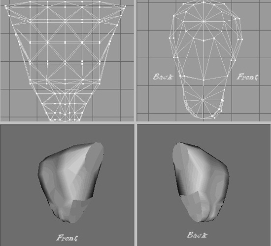
25. By now, you should be getting fairly adept at using the Select, Move, and Scale tools in MilkShape, so I’ll give you a little assignment. Make the scalp region at the top of the head look like the scalp shown in Figure 14.17, using just these three tools and operating only on the top row of vertices. You will have to work in both the Front and Side views while monitoring your progress in the 3D view. Note that the 3D view in Figure 14.17 is smooth-shaded, not flat-shaded like most of the other figures.
Figure 14.15
Dragging the vertices forward.
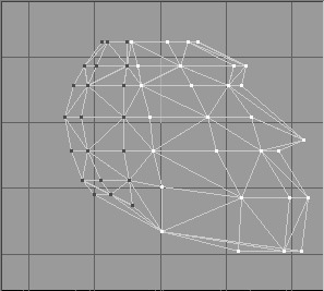
Figure 14.16
After dragging the vertices.
26. Next, use the same techniques to shape the nose and eyes. Figure 14.18 shows which vertices to use to shape the nose. Scale the vertices by 50 percent in the X-axis.
27. Shape the eye-socket vertices, as shown in Figure 14.19, by scaling to 30 percent in the X-axis.
28. Now this entire work should exist as one group. Rename that group as “head” in the Groups tab in the toolbox.
29. Save your work in your game folder as artshapesactorsheromyhead.ms3d. By saving the head in its own file, you can keep it safely out of the way while you work on the other parts.
Figure 14.17
Shaping the scalp.
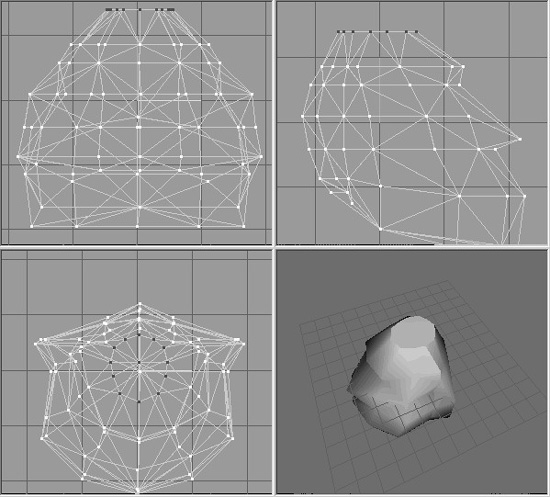
Figure 14.18
The nose vertices before scaling.
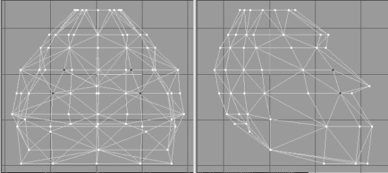
Figure 14.19
The eye-socket vertices after scaling.
30. Save your work one more time, but this time as artshapesactorshero myhero.ms3d. This is the Hero model that we will build up as we go along.
And there you have it—as you can see in Figure 14.20, steely-eyed, big-jawed, beetle-browed genuine dyed-in-the-wool hero material!
Figure 14.20
The finished Hero head.

The Torso
Like the head, the torso will be based on the cylinder shape, but this time we will use two of them and weld them together.
1. If you have the head file still open, leave it open. If you don’t have it open, then open it, or you can open myhero.ms3d. Either one will do, because they both contain only the head so far.
2. Save the file in your game folder as artshapesactorsheromytorso.ms3d. We want to have the head around to use as a sizing guide when we start the torso model, and then we will delete it.
3. Drag the head mesh up until it is three or four grid lines above the model origin (the 0,0,0 coordinate), as suggested in Figure 14.21.
4. Use the Cylinder shape, and make one that has 6 segments, or stacks, and 12 slices, or faces. Give the name “chest” to the group it creates.
5. Rotate the cylinder by 90 degrees in both the X- and Y-axes.
6. Move and scale the cylinder until it has the same relationship to the head, as shown in Figure 14.22.
7. If the Auto Tool option is on, then turn it off.
8. In the Front view, select all the vertices from one end of the cylinder, then hold down the Shift key, and drag over the vertices at the other end of the cylinder to select them as well. These vertices form the cylinder caps for either end.
Figure 14.21
Positioning the head mesh.
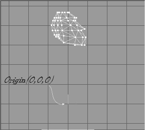
Figure 14.22
The relationship of the chest cylinder to the head.
Tip
When trying to use the Shift key to add to a collection of selected objects, you might need to press the Shift key a couple of times. That’s because when you are in certain modes, like Move mode, holding the Shift key toggles between zooming the view using a mouse drag, and adding to the collection.
9. Scale the vertices to 50 percent in the Y- and Z-axes.
10. Drag the vertices up until the top ones are in line with the top of the cylinder. Figure 14.23 shows what the result should look like, with the head hidden. We’ll keep the head object hidden for the next little while.
Tip
To hide the head, just make sure that it is the only object selected, then choose Edit, Hide Selection. You need to make sure that all the faces (triangles) in the head object are selected, not just the vertices. The best way to ensure that you select the head the right way is to open the Groups tab, highlight the head object in the list, and click the Hide button.
Figure 14.23
The cylinder caps after scaling and moving.

11. If you like to use the Auto Tool option, turn it back on now.
12. In the Front view, select the right-hand end cap, and rotate it by −20 degrees in the Z-axis.
13. Now rotate the left-hand end cap by +20 degrees in the Z-axis.
14. Next we will delete the head and we will need to manage our files during the process. So pay close attention here.
First, save your current work as myhero.ms3d. That should have saved the torso and head together in the myhero.ms3d model. Then in the Groups tab in the toolbox, choose the head group and delete it. Then save again, this time saving as mytorso.ms3d. This gets the head out of the way so it won’t clutter our model. We have the head already saved separately, so no worries here. We’ve also saved our torso in its own file for possible future use as a component in some other model. Now we can get back to working on building up myhero.ms3d some more.
15. In the Top view, select the two vertices in the middle at the bottom, in the area of the sternum, as shown in 14.24, and move them toward the inside of the chest a bit. Use Figure 14.24 as a guide.
16. Now you’ll do the same for the back as for the front, but just slightly differently, for a different effect. In the Front view, select all the vertices in the top three rows, including the ones that are in the end caps.
17. Hide these vertices, using Edit, Hide Selection.
Figure 14.24
The sternum vertices after moving.
18. Now in the Top view, select the middle three vertices at the top of the view, as shown in Figure 14.25. These are the middle back vertices.
19. Move the middle back vertices toward the inside of the chest a bit, just as you did with the sternum, but perhaps not quite as much.
20. Create another new cylinder (to be named “ab”), and give it the same 90-degree rotation in the X- and Y-axes.
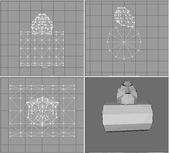
21. Move and scale the ab cylinder until it has the same relationship with the chest, as shown in Figure 14.26.
Now we have our primitive abdomen inserted. We’re going to have to splice that mesh onto the chest mesh in order to complete the torso. It’s actually not terribly hard to do, and after you’ve done it once, it will seem intuitively easy. But there are quite a few fiddly little steps involved to get there from here. So please be patient.
Figure 14.25
The middle back vertices.
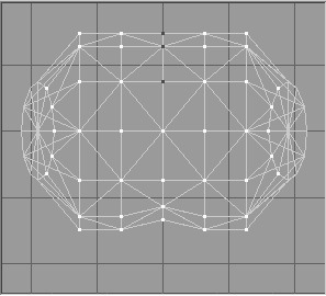
Figure 14.26
The ab cylinder relative to the chest.
22. Using the Groups tab, hide the ab mesh.
23. In the Right Side view, select the bottom vertices, as shown in Figure 14.27, and then hide them using Edit, Hide Selections.
Figure 14.27
Hiding the lower chest vertices.
24. Back to the Groups tab, unhide the ab mesh by clicking the Hide button (which toggles between hiding and unhiding each time you click it). Don’t use the general Unhide All command, because we want the chest vertices that we just hid to stay hidden.
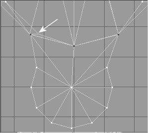
25. In the Right Side view again, select the vertices shown in Figure 14.28, and drag them up so they are directly over the location where the hidden vertices for the chest are. Study Figure 14.28, which shows the vertices selected and dragged into position. Compare it with Figure 14.27 to get a sense of the right place to put the vertices. The intersection of lines shown by the white arrow in Figure 14.28 does not get a vertex at this time—we will deal with that shortly.
Figure 14.28
The ab vertices dragged over on top of the chest vertices.
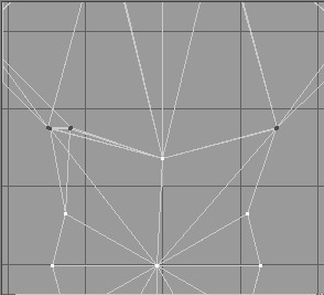
26. In the Front view, locate the end cap vertices, as shown in Figure 14.29, and drag them out to the position indicated in that figure.
Figure 14.29
Dragging some end cap vertices over on top of chest vertices.
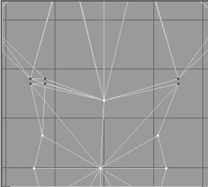
27. Next, do the same for the vertices to the left of the previous set. Drag them to exactly the same place as the previous set, as shown in Figure 14.30.
Figure 14.30
Dragging the end cap neighbor vertices over on top of the chest vertices.
28. Repeat steps 26 and 27 for the other end of the ab mesh.
29. Drag the next set of vertices over to the chest positions, as shown in Figure 14.31.
Figure 14.31
Dragging the next set of vertices into position.
30. Repeat the drag operation for the other end. You should now have something that closely resembles the layout in Figure 14.32.
31. Zoom in on all the places that you dragged vertices to, and make sure that they are exactly over the line intersections of the chest triangles.
32. In the Right Side view, select and hide all vertices on a line from the center of the cylinder forward (with forward being toward the right of the view). Figure 14.33 shows the vertices we’re interested in.
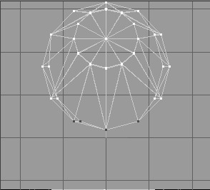
33. Back in the Front view, select the center vertex at the top of the ab cylinder, as depicted in Figure 14.34. If you’ve done step 32 correctly, then as you scan around the other views, you will see that only one vertex has been selected.
Figure 14.32
The final Front view layout.
Figure 14.33
Select and hide these vertices.
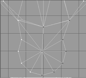
Figure 14.34
The top center cylinder vertex.
34. Switch to the Right Side view, and drag that lone vertex up to the spot that I pointed out with the white arrow back in Figure 14.28.
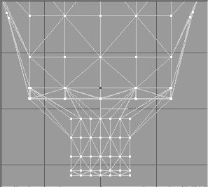
You should now have a configuration that looks like the one shown in Figure 14.35. Again, take the time to zoom in and ensure that all the dragged vertices are exactly over the line intersections of the chest triangles.
35. Unhide all the hidden vertices using the Edit, Unhide All command.
36. Select all the vertices from both meshes located at the places where you placed the dragged vertices. It’s probably best to do this with the Right Side view, as I did in Figure 14.35. These are the vertices of each mesh, chest, and ab, that share the same locations.
Figure 14.35
Selecting the common chest and ab vertices.
37. Choose Vertex, Snap To Grid. This should have the effect of forcing the closely adjacent vertices of each mesh to exactly align on the grid locations. However, if your vertices weren’t aligned closely enough earlier, then they might diverge, as you can see happened to me in Figure 14.36. That’s because I didn’t take my own advice to zoom in and tweak each moved vertex position to be exactly right.
Figure 14.36
After snapping to grid…oops!
It should be pretty obvious where the misaligned vertices have to go. If you have any that wandered off like I did, go back to the Right Side view and the Front view, and move the wayward vertices into position. Then repeat the Snap To Grid operation.
38. Compare your results with the images in Figure 14.37, making sure you have the same thing as shown there.
Figure 14.37
The well-aligned vertices.
39. If they aren’t already selected, reselect the vertices shown back there in Figure 14.35.
40. And now for the moment we’ve all been waiting for: choose Vertex, Weld Together.
All vertices that share identical common coordinates will be “welded” together. This basically means that superfluous copies of vertices will be deleted, and the polygons that we’re defining will be reattached to the remaining single copy of each vertex.
41. In the Groups tab in the toolbox, choose both meshes, the chest and ab, so that they are both selected and highlighted in the wire-frame views.
42. Click Regroup, and then rename the newly consolidated group as “torso”.
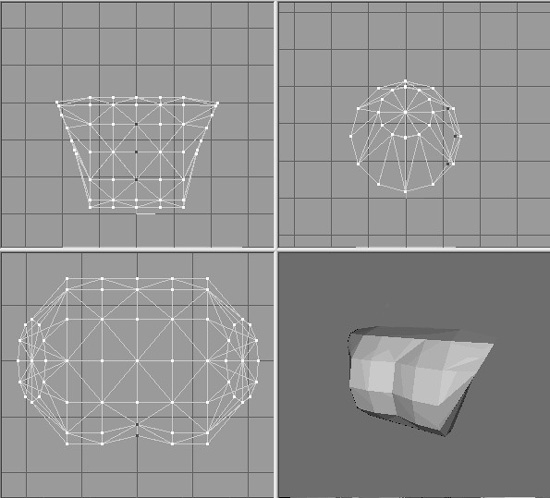
You can now consider the torso to be finished. However, you can probably see areas where you can make obvious tweaks and adjustments. I did a few, just to make the integration of the back and the behind, as well as of the chest and the front abdomen, a bit more natural looking. I also added a wee bit of anatomical correctness, so to speak. Figure 14.38 shows the results of my tweaks. It should be fairly painless for you to duplicate these adjustments. The only operations I performed were Select (Vertex) and Move.
43. Save your mytorso.ms3d file so you don’t lose all your work.
44. Open your myhero.ms3d file, and delete the older version of the torso group that is in this model.
45. Then merge the mytorso.ms3d file that you saved in step 43 into this model and save the whole shebang again as myhero.ms3d.
This updates myhero.ms3d with the latest and greatest version of your torso. The myhero.ms3d file should now contain the finished head and the finished torso.
As we create the remaining parts of the model, we’ll add them to the myhero.ms3d model by merging as we go along.
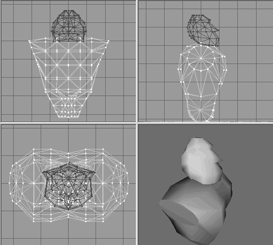
Matching the Head to the Torso
Now we should make sure that the torso and the head match correctly.
1. If the head and torso are nicely aligned, close to what you see in Figure 14.39, then you are done with this section, and you can skip to the “The Legs” section, which comes up next. Otherwise, continue on to step 2.
2. On the Groups tab in the toolbox, choose the head object (your torso mesh will be called “torso”, so the head mesh will be the other one). Rename it as “head” if it isn’t already called that.
Figure 14.39
Positioning the head.
3. Deselect the torso, and then click the Select button so that the head mesh is highlighted (and the torso mesh isn’t), drag the head around in either the Front or the Side view, and position it as shown in Figure 14.39.
I see two things I don’t like right away. The head is bigger than it should be, and its shape seems to be a little too…ummm…blah. This isn’t hard to fix, however.
4. Scale the head to 75 percent in the Y-axis only.
5. Move the head down until it just touches the top of the torso.
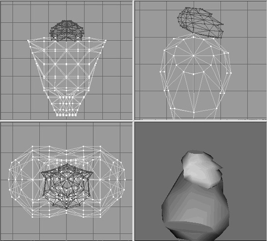
6. Rotate the head by 5 degrees around the X-axis so that the face is pointing a little bit down, as shown in Figure 14.40.
There, that’s more like it! Now to fiddle with the torso some more. If you liked the head better when it was bigger, simply choose Edit, Undo until you get the larger head back.
Figure 14.40
The reshaped head.
7. Select the vertices that form the shoulder sockets on both sides of the torso, using Figure 14.41 as a guide.
8. Scale the vertices to 60 percent in the Y- and Z-axes.
9. Save your work in your game folder as artshapesactorsheromyhero.ms3d.
10. If you changed the head, you need to delete the torso, then save the file as myhead.ms3d to preserve your changes to the head. Then choose Edit, Undo until you get the head back.
11. Delete the head, and then save the file as mytorso.ms3d.
Now the head, torso, and overall hero files have been created, aligned, and their corresponding files are up-to-date.
Figure 14.41
The shoulder socket vertices.
The Legs
When we start the legs, we’ll want to keep the torso mesh around to use as a sizing reference, at least for the first little while. However, we won’t need to have the head mesh in there, cluttering things up, so we’ll get rid of that.
1. If you haven’t done it already, open your torso file, found in your game folder as artshapesactorsheromytorso.ms3d.
2. Now save the same file as artshapesactorsheromylegs.ms3d, and continue working with this version.
3. Hide the head mesh using the Groups tab in the toolbox and the Hide button found there.
4. Select the torso mesh, and drag it up about one torso’s length above the origin.
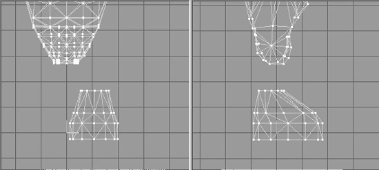
5. Create a cylinder with 3 stacks (segments) and 12 slices (faces), and position and shape it as shown in Figure 14.42. This is the foot.
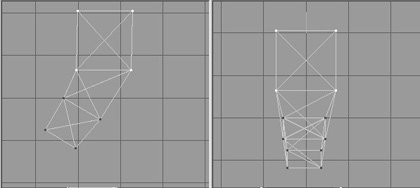
6. Create another cylinder, and rotate it 90 degrees in the Z-axis, making sure that it is oriented so it runs left to right where the knee would be.
7. Using Figure 14.43 as a guide, move the vertices of the top of the foot up to meet the knee cylinder.
By now you’ve probably realized that almost everything from here on is more a matter of style and taste and less of technique. So you should feel free to go ahead and deviate from the specific construction details if you think of something you might like better.
8. Reshape the knee cylinder as shown in Figure 14.43.
Figure 14.42
Shape and placement of the foot.
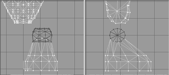
9. Select the foot cylinder, and rename it as “LeftFoot”.
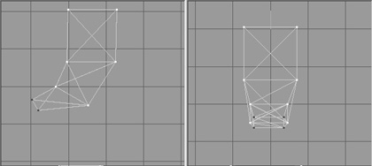
10. Create two more cylinders, and orient them as shown in Figure 14.44 to make the upper leg and hip.
11. Select the two new cylinders, plus the knee cylinder, and use the Regroup tool in the Groups tab of the toolbox. Name the resulting mesh “LeftThigh”.
12. Shape the left thigh to match that shown in Figure 14.45—or to suit your own evil purposes.
13. With the left foot mesh selected, choose Edit, Duplicate. A duplicate of the leg is created in exactly the same location as the original, so you can’t see it yet.
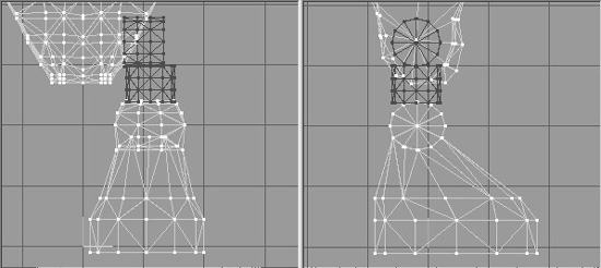
Figure 14.45
The finished left leg.
14. Choose Vertex, Mirror Left<--> Right. The duplicate leg mesh now appears on the other side, and in the right place, or pretty darn close.
15. Rename the new leg mesh as “RightFoot”.
16. Now duplicate and mirror the left thigh in the same way, renaming the new thigh mesh as “RightThigh”. You should now have two legs, each made up of a thigh mesh and a foot mesh and named appropriately.
17. Next, delete the torso and head meshes from the model.
18. Save your work! You should be saving this as artshapesactorsheromylegs.ms3d.
Integrating the Legs to the Torso
Just as we did with the head, we now have to integrate the legs with the rest of our model.
1. Open the file artshapesactorsheromytorso.ms3d in your game folder.
2. Select File, Merge, and choose the legs file you just created, which should be called artshapesactorsheromylegs.ms3d.
3. Choose the right foot, right thigh, left foot, and left thigh meshes, and move them into position. You should now have a model pretty close to the one shown in Figure 14.46.
The Arms
Finally, the last set of meshes in the model. We can create the arms in exactly the same way we created the legs—building up from shape primitives, splicing them together until we have the desired mesh topology.
With arms comes the perennial question, what to do about the fingers? In some models we can make detailed meshes for each finger, with cylinders segmented at the knuckles, and so on. However, we must keep in mind that our goal here is to create a low-poly model, and that typically means fewer than about 1,500 polygons in the model. If we go over that count by a small amount, no big whoop, but we must remain mindful of it.
So, let’s get to work! We’ll start with the left hand.
1. Open your saved mytorso.ms3d file, and resave it as myarms.ms3d in the same location as your other work files.
2. Create a box offset to the left side (on the right in the Front view) of the torso, situated low, near the bottom of the torso.
Figure 14.46
The Hero model with head, torso, and legs.
3. Duplicate this box, and move the copy to abut the bottom of the original box.
4. Scale the second box to 80 percent.
5. Duplicate the second box, and move the new box below the second.
6. Scale the third box to 80 percent of the second box.
7. Align the boxes as shown in Figure 14.47.
8. Hide the torso mesh to keep it out of the way for the moment.
9. Using Vertex Selection, the Move tool, and the Snap To Grid and Weld tools as you did with earlier parts of the Hero model, align the vertices of the three boxes as shown in Figure 14.48, and weld the vertices together.
10. Rotate the two bottom rows of vertices by −30 degrees in the Z-axis, as shown in Figure 14.49.
11. Move the two bottom rows in the Front view to align them as shown in Figure 14.50.
Figure 14.47
Alignment of the three boxes.
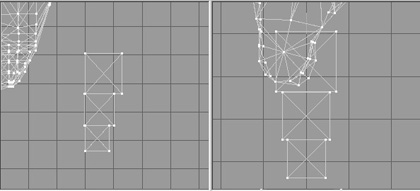
Figure 14.48
Welding the hand vertices.
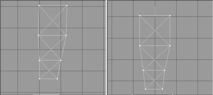
Figure 14.49
Rotating the two bottom rows.
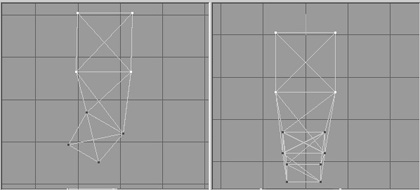
Figure 14.50
Moving the two bottom rows.
12. Rotate and move the bottom row of vertices to match what is shown in Figure 14.51.
Figure 14.51
The bottom row of vertices.
13. Now, setting the Select mode to Group, select all the groups of boxes, duplicate them, and move them forward to abut the front of the original boxes, using Figure 14.52 as a guide.
14. Repeat the process in step 13, putting the new copies at the rear of the originals, using Figure 14.53 as a guide.
15. Repeat the duplicating process one more time, but this time move the new boxes to the left side of the Front view. This is the thumb.
Figure 14.52
Two sets of shaped boxes abutting each other.
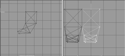
Figure 14.53
Three sets of shaped boxes.
16. Choose Vertex, Mirror Left <--> Right to reverse the orientation of the thumb boxes (see Figure 14.54), and then scale the thumb to 50 percent.
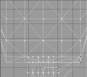
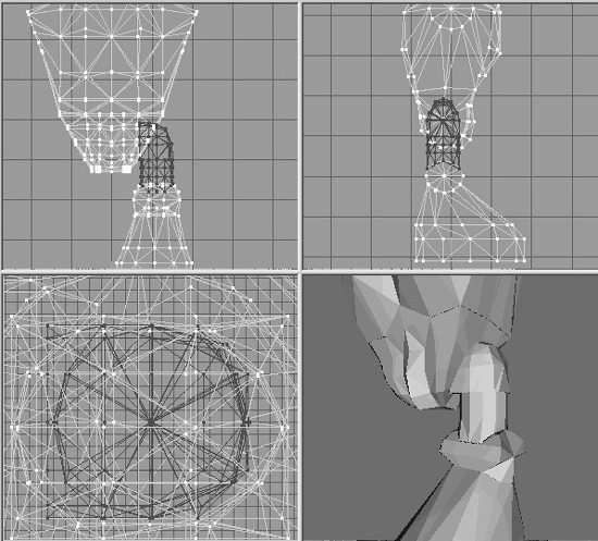
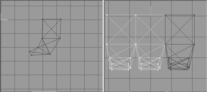
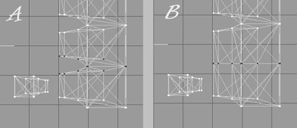
17. Now we’ll switch back to the hand part. In the Top view, select the vertices that are adjacent in the two forward parts of the hand boxes, as shown in Figure 14.55, panel A. Then choose Vertex, Flatten, Z, and the vertices will be brought together onto a common plane, as shown in panel B of Figure 14.55.
18. Double-check the other views, and if all vertices look to be coincident, then choose Vertex, Weld Together to weld them.
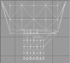
19. Repeat step 18 for the rear part of the hand, welding the result. Compare with Figure 14.56 to make sure it is correct.
Figure 14.54
The start of the thumb.
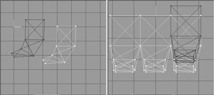
Figure 14.55
Welding the hand vertices.
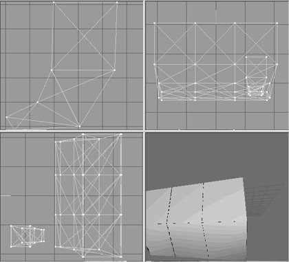
20. Select the rearmost vertices, in the baby finger area, and scale them to 50 percent in the X- and Y-axes, as shown in Figure 14.57.
21. Move the scaled vertices forward until they are close to the middle hand boxes, using the Top view in Figure 14.58 as a guide.
22. Repeat steps 20 and 21 for the front index finger area.
23. In the Front view, rotate and shape the thumb to approximate what’s shown in Figure 14.59.
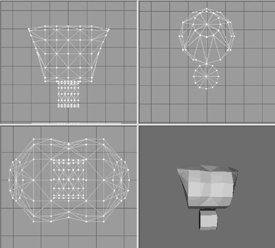
24. Unhide the torso, and compare the size and positioning of your hand with the views shown in Figure 14.60. Rotate the hand to match, if required.
Figure 14.56
After the hand welding.
Now you might be thinking that the hand looks awfully blocky compared to other parts of the model. You are right, but take heart. We can compensate for this with our skins. Remember, we want to keep our polygon count as low as we can.
25. Using the Groups tab in the toolbox, select all the hand groups, regroup them to form a new mesh, and rename it as “LeftHand”.
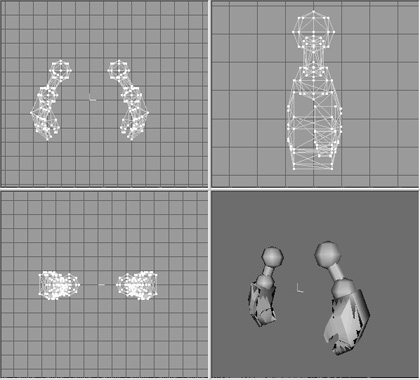
26. In the Front view, use the Sphere tool set to four stacks and eight slices, and create a sphere that completely fills the left shoulder socket of the torso. Check all your views to make sure that you have it pretty close.
27. Make another sphere with the same settings that fill the top of the hand, and place it there.
28. Make a one-stack, eight-slice cylinder that you can rotate, and move it into a position that connects the two spheres. Use Figure 14.61 as a guide for sphere and cylinder sizing and placement.
Figure 14.57
The scaled baby finger area.
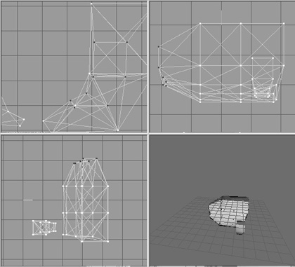
Figure 14.58
Placing the scaled baby finger vertices.
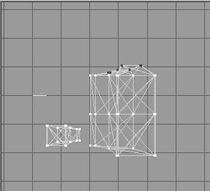
Figure 14.59
The thumb positioning.
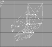
Figure 14.60
Comparison of torso with hand.
29. Select all the upper arm components, regroup them, and name the new mesh “LeftArm”.
30. Select the new left arm mesh, duplicate it, and then choose Vertex, Mirror Left <-- > Right.
31. Adjust the new mesh if necessary, and rename it as “RightArm”.
32. Repeat the duplicating and renaming operations for the left hand mesh, calling the newly duplicated copy “RightHand”.
33. Delete the torso mesh.
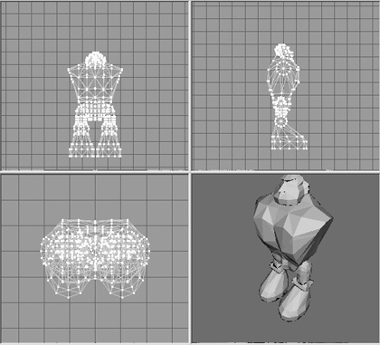
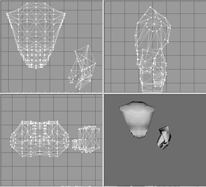
34. Save your work! You should now have a pair of hefty arms that closely resemble those shown in Figure 14.62.
Figure 14.62
The completed arms.
Integrating the Arms to the Torso
Once again, it’s integration time. If you are inclined to wonder about doing the model this way rather than all at once in one file, I want to point out that now you have a different source model file for each major component of your model. This allows you to make different mix-and-match models using the same components over and over. Just make three sets of arms, four sets of legs, five heads, two torsos, or something like that. Mix ‘n’ match ’em, and you’ll have all sorts of different model configurations!
1. Open the file artshapesactorsheromyhero.ms3d in your game folder.
2. Select File, Merge, and choose the arms file you just created, which should be called artshapesactorsheromyarms.ms3d.
3. Choose both the right arm and the left arm meshes, and move them into position. You should now have a model pretty closely resembling the one shown in Figure 14.63.
Figure 14.63
The completed Hero model.
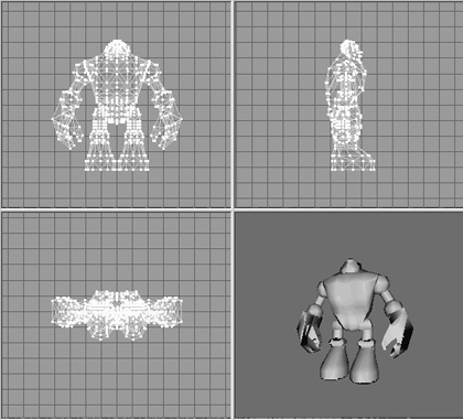
Finally, we need to scale our mesh to the correct size. We want our guy to be around 2 meters tall. We are going to export at a 1:1 scale, so we need to set the top of the head to be close to 2.0 units high in the Y-axis as measured from the scene’s origin (the 0,0,0 center of the scene, where the three colored lines of the axis bug intersect). Use the Scale tool and one of two methods: (1) eyeball the height of the character as he exists now (move your cursor to the top of his head in the Side or Front views, and get the Y-axis value in the status bar of the window at the bottom left), calculate the scale in your head (or with a calculator), and enter the appropriate scale value in all three scale fields of the Scale tool (the same value for all three), or (2) click-drag the mouse in each of the views until you shrink or grow the model to where you want it. I personally prefer method 1—I get more consistent results, and it only takes two or three scale adjustments at the most.
Select the entire model and move it so that the feet straddle the axis bug, while resting squarely on the X-axis line in the Front view. The X-axis line in the bug is colored yellow.
TESTING THE TOOL CHAIN
As you may have noticed by now, when we create art for games, we use an assortment of third-party tools to generate our various kinds of artwork.
Party On, Garth!
A third party is some entity that provides tools and resources used in a particular system context but that is (1) not the user of the system and (2) not the creator of the system.
An example in the context of computer systems: when you are using a computer system made by Dell, Dell does not make the operating system—Microsoft does. So in this context, you are the first party, Dell is the second party, and Microsoft is the third party.
In the context of operating systems: when you are using Windows to create flyers for your bowling league, you are the first party, Microsoft (who makes Microsoft Windows) is the second party, and your drawing software is made by a third party—unless you use Microsoft Paint, in which case there is no third party. I hope. Okay, let’s not get too deep into this….
Anyway, in the context of game engines, Torque 3D is the product of Torque, the second party. MilkShape 3D, Gimp, UVMapper, and so on, are all third parties.
Oh yeah, and whatever happened to Garth, anyway?
At the start of any project, or whenever any new tools are brought to bear on the project workload, there is an activity that should be performed called testing the tool chain, or sometimes proving the tool chain.
The idea is to create some art resource, at a minimal effort, perform all the steps required to get that resource into the game engine, and then use the game engine to actually view the art resource. Each time a new “layer” of resource complexity is added, the first step should be to test the tool chain with a minimal example of the new complexity. Thus, we build up our model in an incremental, step-wise fashion.
If you are familiar with the “cyclone,” “tornado,” or “spiral” development methodologies (essentially that’s just three names for the same thing), you will find that the incremental approach is an ideal fit. If you aren’t familiar with development methodologies, don’t sweat it. Just understand that building up your model in a step-wise fashion is both intuitive and easy on the brain, not to mention that it fits well with current project management and development pipeline best practices. The primary advantage (and it’s a huge advantage) is that most design or implementation errors are detected very early on and fixed right away, so that they don’t fester and end up infecting an entire project.
Here, look at this:
Modeling Work Flow
1. Create character model.
2. Export model to game engine format.
3. Insert mesh into game environment.
4. Run game and view model in game environment.
5. Add UV-mapped skin texture.
6. Export model to game engine format.
7. Insert mesh into game environment.
8. Run game and view model in game environment.
9. Add rigged skeleton with no animations.
10. Export model to game engine format.
11. Insert mesh into game environment.
12. Run game and view model in game environment.
13. Add one animation, usually idle or root.
14. Export model to game engine format.
15. Insert mesh into game environment.
16. Run game and view model in game environment.
17. Add another animation.
18. Export model to game engine format.
19. Insert mesh into game environment.
20. Run game and view model in game environment.
21. Rinse and repeat steps 17 to 20.
Notice how we add complexity to the model a little bit at a time, and each time we add to it, we test the model in its final context. Traditionally, that first export in step 2 is the “testing the tool chain” part. The rest is just sensible work flow. Note that the UV-mapped skin texture series of steps don’t need to happen before the rigging and animation steps, and therefore we don’t need to wait until the guy doing our textures and UV mapping is done before we create and test animations.
You should be aware that the previous section of this chapter, “The Base Hero Model,” was the equivalent of step 1 in the modeling work flow procedure.
So let’s try it testing the tool chain right now.
Make sure you have MilkShape 3D running and you’ve got your freshly completed Hero model open and on full display.
1. In MilkShape 3D, choose File, Export, Torque DTS Plus. You will see the Torque DTSPlus Exporter dialog box appear.
Caution
Do not use the Torque 3D Game Engine DTS Exporter. In fact, don’t use it at all in this chapter.
2. We’re going to take the defaults, but we should make sure they are correct. You want to have the following checkboxes enabled:
![]() Output dump file
Output dump file
![]() Copy Textures
Copy Textures
You should probably always have Output dump file enabled. The file that is created is called dump.dmp, and it will be in the same folder that you exported your model to. You can look in it for errors if things don’t work right. You should delete all dump files before shipping your game.
Copy Textures is a nifty and very handy feature that allows you to keep your source model and its texture files in a location far removed from the game folders. When you export to the appropriate location in the game folders, any textures that your model uses will be copied to the same folder as the exported DTS version of your model. Muy cool.
Make sure you have the Scale field in the Options pane set to 1.
Click Apply to save your settings, and then click Export DTS when you are ready to close the dialog box and perform the export.
3. When prompted, save your DTS output file in your game folder as artshapes actorsheromyhero.dts.
That was pretty painless. That’s step 2 of the work flow done. We’ll dust off the Torque 3D Toolbox and check out the model.
1. Launch Torque 3D and open the FPS Example Blank Room in the World Editor.
2. Ensure that the Shape Editor tool is selected. It’s the last one on the right.
3. In the Shapes tree, click the Library tab and then navigate to artshapesactors hero. Double-click myhero.
4. The model should appear in the center of the screen.
5. Hold down the right mouse button and use your mouse to rotate the model and bring it closer to you or move it farther away. Right-click and drag will slide the camera around. The mouse wheel will let you zoom in and out.
6. If necessary, go back to your model in MilkShape and make adjustments to your model, and then come back here to check them out.
THE HERO SKIN
Now it’s time to skin the model. In Chapter 9 you learned how to create the textures for skins, and in Chapter 13 you learned how to do simple UV mapping for skins. Next, we have to do the UV mapping for the player-character, which is somewhat more complex. We are not going to go over the creation of the texture for Hero character skin. The Resources folder includes a mapped Hero skin texture for you to use, but I encourage you to make your own in the same fashion as the one for the Standard Male.
1. If MilkShape 3D is not already running, launch it and open your Hero model, located in your game folder at artshapesactorsheromyhero.ms3d.
2. Choose File, Export, Wavefront OBJ, and export your Hero model as artshapes actorsheromyhero.obj.
3. Launch UVMapper (found at 3D3ETOOLSUVMAPPER), and maximize the window.
4. Load the artshapesactorsheromyhero.obj. You will see a crazy quilt of lines. This is the “default” mapping created by MilkShape. Let’s forget about that, because we are going to create our own mapping.
5. Choose Edit, New UV Map, Planar, and then use the settings shown in Figure 14.64. These are the default settings so you probably won’t have to make any changes. Click OK when finished adjusting these settings.
6. Choose Edit, Color by Group. Your screen should now look like Figure 14.65. Of course, your version will be in color, and so the light yellow will actually be more visible to you. In the figure, which has been converted to grayscale, the yellow has become a very light gray.
Figure 14.64
Planar mapping settings for Hero model.
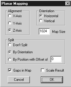
Figure 14.65
The unwrapped Hero model.
7. First, choose Edit, Select, All, and press the forward slash (“/”) key on the numeric keypad to shrink the selection to 25 percent, half-sized in the x dimension and half-sized in the y dimension (the asterisk [“*”] on the numeric keypad will do the opposite). Press Enter to save your adjustment. If you don’t like the adjustments you just made, press Esc to undo your changes since making your last selection or remapping. If you’re working on a laptop without a keypad, click and drag the selection to the right and down to shrink it to approximately 25 percent.
8. Choose Edit, Select, by Group, choose the group “head”, and then click OK.
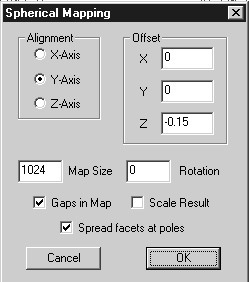
9. Choose Edit, New UV Map, Spherical. Use the settings shown in Figure 14.66.
Figure 14.66
Settings for the spherical mapping of the head.
10. Press the equal sign (“=”) to expand the head selection to fill the window, and then press the forward slash on the numeric keypad a few times to shrink the selection. Use your mouse to drag the head to the upper center of the window, as shown in Figure 14.67.
Now you might notice that there appears to be two triangles out of place in the head unwrapping. Look inside circle A in Figure 14.67 and see if you can spot them. In your model this may not be the case, but the more closely your model matches the one I’ve done here, the more likely this is to happen. This little oddity is easily fixed. You should be able to do the mapping without that happening—it’s all a matter of which settings you use. You can try to get the right settings by trial and error. However, the simplest fix is to just move the miscreants to their lawful location. So that’s what we’ll do.
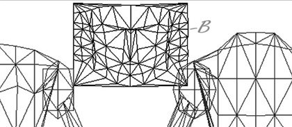
11. Drag your cursor over the middle of the two wayward triangles. Don’t touch any parts of any other triangles in any other part of the model. The triangles will now appear surrounded by a selection box.
12. Click and drag them over to the right-hand side where there is that suspicious-looking gap, and place them as well as you can. Location B in Figure 14.68 shows where the triangles end up.
Figure 14.67
The unwrapped head.
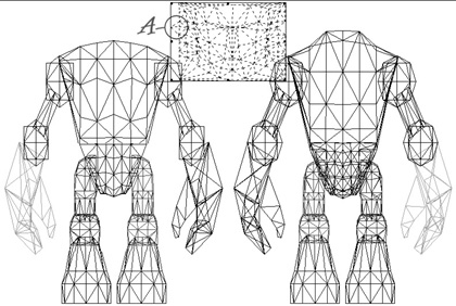
Figure 14.68
The adjusted triangles.
13. Use the arrow keys to adjust the position of the triangles. There you go!
Now you need to do a bit of housekeeping-like fiddling.
14. Choose Edit, Select, All. You will get everything on the screen selected in a selection box with the little black sizing handles at the corners and midway along each side.
15. Grab the sizing handle on the right side. Your cursor should change to the left-right sizing cursor (this is an arrow pointing left and right).
16. Drag the sizing handle toward the left until you get a blank space on the right a little wider than the width of the head.
17. Choose Edit, Select, Group, and choose the head. Drag it over to the upper right, in the blank space you just created. You should now have a layout like Figure 14.69.
Figure 14.69
The reorganized map.
As you work you will probably reorganize your layout a few times—that’s perfectly normal. You want to keep it clean and make sure your items are easily selectable.
18. Now choose Edit, Select, By Group, and choose the LeftHand group.
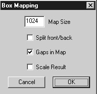
19. Choose Edit, New UV Map, Box. You will get the Box Mapping dialog box, as shown in Figure 14.70. Make sure you have Split front/back turned off, and Gaps in Map turned on. Click OK.
The unwrapped left hand will appear in the window, surrounded by the selection box.
Figure 14.70
The Box Mapping settings.
20. Move and size the hand mapping, just as we did with the head, placing it in the center of the window in the blank area. Make sure it is small enough to allow the mapped right hand in here as well (see Figure 14.71).
Figure 14.71
The UV-mapped hands.

21. Perform the same UV-mapping operation and placement operation on the RightHand group, putting them in the center space.
22. Next, map the left and right feet the same way. For each group as you unwrap it, size the sole (oval shape) so that it is longer than it is wide. Place the feet underneath the main model, as shown in Figure 14.72.
Figure 14.72
The UV-mapped feet.
23. Next, map all the arms and legs. Use Planar mapping for these.
24. Shrink and move the mapped objects, ensuring that no mapped objects overlap any others.
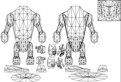
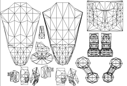
25. Once all the objects are mapped, overlap similar items (with the exception of the torso front and back), and enlarge the torso, hand, and head objects as much as possible. The larger the mapping, the more detail can be applied in the texture.
26. Finally, move and arrange the objects to match the layout in Figure 14.73. This is the final texture-mapping layout that we’ll use for the template.
27. Choose File, Save Model, and save it in your game folder as artshapesactors heromyhero.obj (thereby obliterating the one you created from MilkShape; don’t worry though—you can always export another from MilkShape if needed).
In the Save Model dialog, the following options should be checked: Export Normals, Export UV Coordinates, Export Materials, and Export UVMapper Regions. The rest of the options should be unchecked.
28. Choose File, Save Texture Map, and save the map as artshapesactorshero myhero.bmp. Make sure the texture size is set to 512 by 512.
29. Launch MilkShape 3D, and create a new file.
Figure 14.73
The final UV-mapping layout.
30. Choose File, Import, Wavefront Obj, and import the artshapesactorshero myhero.obj file.
31. In the Materials Tab of the toolbox, click New.
32. Click the top Texture button, and locate the artshapesactorshero myhero.bmp texture map template file you created in UVMapper.
33. Rename the material as “heroskin”.
34. Using the Groups tab, select all the meshes, and then switch back to the Materials tab and click Assign. You have to select each mesh one at a time, click Select, and then select the next mesh until all meshes are selected. You should now have a 3D view that resembles Figure 14.74.
Of course, your version is in color. The lines of the triangles in the color groupings assigned in UVMapper are clearly visible. You are now in a position to go ahead and use Gimp to create your skin for the Hero model. Refer back to Chapter 9 if you need a refresher. Make sure to save your skin as a JPG file type in order to use it in Torque 3D. This means that you will also have to go back into MilkShape and redefine your material to point at the JPG version and not the BMP version.
Figure 14.74
The 3D view showing the UV template texture.
If you are wondering why the exercise in Chapter 9 didn’t make a skin for use on this model…I mean, well come on! Do you want me to do everything for you? Ya lazy bums! Make your own danged skins. They’re likely to be 10 times better than mine anyway.
Now, if you are finished with your griping, you need to test your UV mapping. Export your hero using the method we used in the previous exercise and then use the Torque 3D Shape Editor to view your model the same way you did back in the “Testing the Tool Chain” section.
If everything looks good with the UV mapping, we’ll continue into the animation section using the UV template Hero skin that I’ve included in the 3D3E RESOURCESCH14hero.jpg file.
CHARACTER ANIMATION
Well, a static model—no matter how cool looking when it’s standing there—is not terribly interesting in a first-person shooter. We’re going to have to animate that sucker!
If we were a big-name, big-money shop, we might go out and hire a motion capture studio to make our animations. But we’re not—we’re indie developers! So we will have to explore other options, and there are some.
On the Internet you can find some stop-motion photography sequences that might help you develop your character animations. There are also freely downloadable files with character animations in them; they will probably have a different skeleton structure than the one we use here, but a certain amount of tweaking can go a long way.
I know someone who manually creates animations using action figures that he poses, changing the poses step-by-step as he works through the animation, converting what his eye sees into the appropriate frame in his animation program. This is certainly a good low-budget option.
In this book we are going to hand-build our animations, because the point is to learn how to do it. They may not be the best animations in the world (or maybe they will be!), but they will be your very own if you make them yourself. If you need a model, ask a friend or family member to step slowly through whatever it is you are trying to animate, if it’s humanly possible. You’d be surprised how helpful that can be. Bribe them with their favorite dessert or something.
Animating Characters in Torque 3D
The general method for making animated characters for use in Torque 3D is to construct a skeleton that corresponds to components of the model and then attach that skeleton to the corresponding components in a process called rigging. We then create a sequence of keyframes—essentially a series of skeleton poses. When the Torque 3D Engine wants to animate the model, it calculates the positions of the meshes in the model by the position and rotation of the nodes (the joints where the “bones” of the skeleton connect to each other) based on where the keyframes appear in the animation timeline.
We are going to create six different basic animations:
![]() root (same as idle in some non–Torque 3D systems)
root (same as idle in some non–Torque 3D systems)
![]() run
run
![]() look
look
![]() head
head
![]() headside
headside
![]() death
death
Table 14.1 shows a complete list of Torque 3D–supported animations. This is not the list of Torque 3D animation sequence files that come with the demo (although all the animations that are supported are indeed included as animation sequences). It’s just that many of the animation sequence files are not automatically invoked by Torque 3D from within the engine or from anywhere in the scripts. Anyway, the ones in Table 14.1 are invoked by the engine or by the demo scripts, as described in the table.
Table 14.1 Torque 3D–Supported Animation Sequences
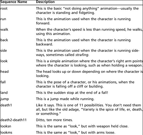
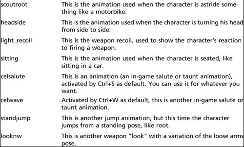
These animations correspond to character animation support built into Torque 3D. The names must match the names used by Torque 3D; however, we can add our own arbitrary animations and activate them from within the script programs if we want. There are also other animations that Torque 3D supports that we won’t cover here.
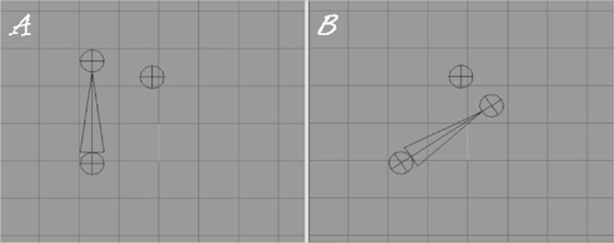
In Figure 14.75 the spheres are joints, or nodes. The spike between two of the spheres is a “bone.” The direction the spike is pointing indicates the relationship between the nodes. The node at the big end is the parent, while the other end is the child node. Notice that in Figure 14.75 the parent node in frame B is rotated 60 degrees in its orientation from frame A, and the child node follows the rotation. The unattached node doesn’t move. Note that the horizontal and vertical lines inside the nodes are angled in the rotated nodes but not in the unattached node.
Open your myhero.ms3d file, if it isn’t already open. Set Joint Size to .05 in the File, Preferences dialog box on the Misc tab. We need to use such a small joint size because the scale of the Hero model is quite a bit smaller than the Standard Male Character model from Chapter 9.
Figure 14.75
Bone movement during joint rotation.
Building the Skeleton
Before we can create the animations, we need to construct the character’s skeleton. We build the skeleton from the bottom-up, so to speak, beginning with the base node and working toward the outer extremities.
1. We will start with the unlink node (or joint), which we place at the origin: (0,0,0). Make sure that you click the Joint tool (lower-right corner of the Model panel, on the right side of the main window), before trying to place the joints.
Tip
To select a joint, click the Joint button in the Select Options frame in the Model tab. You can only do this when the Select tool is active (its button is clicked in the Tools frame).
2. Now make sure that the unlink node is still selected, and then place another node up in front of the head, roughly off the end of the nose, and name this one cam. Figure 14.76 shows the relative appearance of these two nodes in the Side view. This arrangement is independent of the rest of the skeleton. (See the sidebar discussion “Torque 3D’s Biped Skeleton” for an explanation of the unlink and cam nodes.)
Figure 14.76
Location of Bip01 Pelvis and Bip01 Spine nodes.
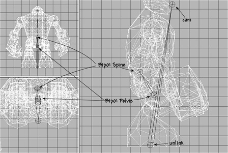
If the unlink node is not selected, you need to select it before creating the cam joint. Do this by clicking the Select tool in the Model panel and then clicking the Joint button in the Select Options frame at the bottom of the Model tab’s panel. Then just click the unlink joint, or click-drag a box around it.
Whenever you create a child node (in this case, the cam joint), you need to have the parent node selected before placing the child. This will make the bone connector appear, thus showing the relationship between the nodes.
3. Now we’ll start on the skeleton itself. This time, make sure that you don’t have any joints selected, while the Joint tool is selected.
4. Place a joint node directly above the unlink node, but up around where the Y value is about 0.7 or so. Name this joint Bip01 Pelvis.
5. Next, while making sure that the Bip01 Pelvis node is still selected, place another joint a little bit above and behind Bip01 Pelvis. Name this node Bip01 Spine. Figure 14.76 shows the relative appearance of these two nodes. Make sure that the big end of the bone that joins these two joints is at the end where the Bip01 Pelvis node is. The big end of the bone is the parent end.
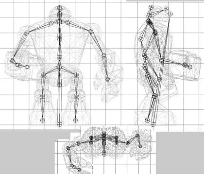
6. Add all the new nodes, and label them appropriately. Figure 14.77 provides a guide to the node placement and their names.
Figure 14.77
The Hero skeleton with labeled nodes.

The order in which nodes are added obviously matters. Here is the sequence for the hero’s skeleton:
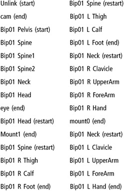
Read the sequence from the top of the left column to the bottom. Then resume at the top of the right column, and work down to the bottom. Nodes that are tagged with (start) are parents only, not children of any other nodes. Nodes that are tagged (end) are children only, and not the parent of any other nodes. Nodes that are tagged (restart) are nodes that already exist, and are listed again in order to show where a particular child attaches. You do not have to make another copy of a (restart) tagged node, just select the one that is already there, and start adding a node to it.
7. Starting with Bip01 Pelvis and moving on to the spine, hips, and shoulders (in that order), adjust the joints of the skeleton to match the skeleton pose in Figure 14.78.
Remember to rotate hip, knee, elbow, and shoulder joints to move the joints at the extremities. You want the character slightly bent at the knee joints, with his left arm bones slightly bent beside him and the right arm bent up at 90 degrees. Pay particular attention to the placement of the Bip01 Spine and Bip01_x_Thigh nodes. Bip01 Pelvis should be well below the level of the Bip01 Thigh nodes, and they should be just a tad higher than the lower spine.
Figure 14.78
The pose-adjusted skeleton.
8. Adjust the mesh rotations, and fine-tune the mesh group placements to match the pose of the skeleton. You might need to fiddle back and forth between the mesh groups and the joint nodes until you are satisfied with the result.
Torque 3D’s Biped Skeleton
The node names and bones you see in Figure 14.77 are somewhat of a standard for Torque 3D. They don’t have to be used, though. There are standard skeletons for other games whose nomenclature you could use instead. Torque 3D uses a standard biped skeleton that is the same as the one used for CounterStrike and other games. As mentioned earlier, if we don’t use the Torque 3D skeleton, with the node names that exactly match, then we can’t use the stock Torque 3D animations.
There are some details about the skeleton and its parts that are really important, and we need to get them exactly right.
The first, and most important, is the node names. Most of the nodes—those that are joints in the “bone structure” of the skeleton—have names that start with Bip01. Any nodes that have this in their names always have a space immediately after the Bip01 string in the name. Additionally, some of the names have an R or L in them to specify right or left side, respectively. These names always have a space after the R or L in addition to the space in front of the R or L. (The space in front is the same space that always follows the Bip01 string.)
So, for example, with the name Bip01 L Clavicle, there is one space between Bip01 and the L and one space between the L and the Clavicle. Got that? Good.
Now, notice in the Side view in Figure 14.77 the node called unlink. This node is not really a required node for our purposes. It comes from a usage requirement when exporting from programs like 3D Studio Max. I’ve included it here anyway, because I wanted a place to attach the cam node to and something that wasn’t part of the main skeleton. With the unlink node, we just need to ensure that any animations that move the entire body forward or back also move the unlink node as well. This will have the effect of seamlessly dragging the cam node along with it. The cam node is a “child” node of the unlink node, but it has no child nodes itself. The unlink node is not a child of any other node, and neither does it have any children other than the cam node.
Now, you could attach the cam node to the head node, for example. The problem with this approach is that the cam node will then move and swivel according to how the head moves in its animations and not simply along with the body in general (the desired effect).
Finally, note that the naming convention used by Torque 3D reflects the fact that the first tool used to make Torque (and Tribes) models was 3D Studio Max. Hence, the node names for the skeleton are names of bones. MilkShape 3D doesn’t model its skeletons with bones for the nodes; instead, MilkShape 3D’s nodes are joints. This is why we have a node called Bip01 R Forearm when the node itself is obviously the elbow (a joint) and not a forearm bone.
Here is a list of Torque 3D’s special nodes and the purposes they serve:
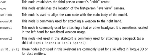
Note that you are not obligated to use the nodes as described above. Different modelers have taken great liberties with the mountn and ski n nodes, though the eye and cam nodes tend to be used for the same purposes by everyone. You can also create your own special nodes for your own uses, like finger and thumb joints for detailed hand movement or jaw, cheek, and lip nodes for facial animations.
Rigging: Attaching the Skeleton
So far we have built the skeleton, named the nodes, and aligned the bones into a pose we like. Next we are going to attach our model to the skeleton. That way, when the skeleton is manipulated, the mesh of the model will follow suit. It is during this step that you might be inclined to thank me for insisting that you retain mesh groups for the different model components like arms and feet and so on!
Rigging the Head
We’ll begin with the head, just to get a feel for the rigging operation.
1. In the Joints tab in the toolbox, choose the joint (or node) named Bip01 Head. Make sure it appears highlighted in red in the wire-frame views.
2. Switch to the Groups tab, and choose the head mesh. It should appear highlighted in red, as you already know.
3. Switch back to the Joints tab, and click Assign. Now the head mesh is assigned to the head node. To double-check, just click anywhere in a blank space in a wire-frame view to make sure that no objects are selected, choose the head joint to ensure it is selected, and then click the SelAssigned (Select Assigned) button. The head mesh should appear highlighted. If not, go back and repeat these three steps.
Aw shucks, there it is—the head is now rigged! Of course, that’s not the end of the story. There is still the rest of the model.
There’s also the issue of what to do when a bone is rigged wrong. Sometimes it’s a trivial fix, and other times you might have to rerig the whole model. Or you might have to rig a model by attaching a node to just a few vertices rather than a whole mesh or submesh. That can get very, um, fiddly—I guess that would be a reasonable description.
Part of the simplicity in rigging this model comes from the technique we used; building from primitives allows us to easily define meshes and submeshes. We’ll use a “one node per mesh” rule of thumb. It can get trickier using other techniques, such as assigning individual vertices to joints, but sometimes those other techniques might be more appropriate for the model you want to build. It’s a judgment call, as everything important tends to be. In fact, we are going to employ a trickier technique—assigning a set of individual vertices to a joint—as the one exception (as there always is) to the “one node per mesh” rule next.
Rigging the Torso
Okay, so the head was a cakewalk. It wasn’t even necessary to show any pictures for you to be able to follow along. How about the torso then—duck soup again, no?
Well, yes…I mean no, actually. No duck soup for this one!
The entire head mesh is attached to the head node, and that is fine. Tilting or rotating the head node will indeed move the head in the manner we want. There really isn’t a whole lot to choose from. The neck is more a part of the spine than the head. The cam and mount1 nodes aren’t even really related to the skeleton. They are special nodes that will have a different role to play in Torque 3D, which we’ll cover later. So that leaves the head node to control the head mesh.
The torso, though, has at least five nodes that it might be attached to. But which should it be? Let’s eliminate the neck node for now. That leaves the three spine nodes and the Bip01 Pelvis node. Actually, we can use more than one node for a mesh, giving different parts of the mesh to different nodes. When we built the torso mesh, we actually combined two primitives together, remember that? One was the chest cylinder, and the other was the abdomen cylinder. We could have left them as two separate submeshes, but I wanted to show you how to join them together. We can still use them as if they were two separate meshes, by assigning their respective vertices to different nodes.
If you look at the nodes, you’ll see that the Bip01 Spine node is pretty well the obvious candidate to control the abdomen part of the mesh. The Bip01 Spine2 node, although probably not as obvious, is likely the best candidate for the other node, for our torso, even though it exists in circumstances dissimilar to the Bip01 Spine. (Bip01 Spine2 doesn’t have limbs attached.) But we’ll go with these two anyway and see how that works out.
What this will mean in terms of animation is that we can have the vertices that are attached to one node move in one way, while the vertices attached to the other node move differently. Or not. It all depends on how you rig it.
None of this worrying about which node to use is strictly necessary. The animations we are going to create don’t actually require the torso mesh to be given more than one node, but it’s a good thing to learn, so we’ll do it.
1. To get started with rigging the torso, let’s tidy up the ol’ drawing board a bit by hiding all the meshes except the torso mesh. If you’ve forgotten how, just go to the Groups tab of the toolbox, choose each mesh, and click Hide. Unfortunately, we can’t selectively hide parts of the skeleton. It’s either all or nothing when it comes to the bones.
It isn’t always necessary to hide all the meshes that you aren’t working with. You just need to ensure that you can easily select the individual vertices that you want in the mesh of interest. In the case of the torso mesh, in the Top view, you can see pretty well every other mesh overlaps the torso.
2. Choose the Bip01 Spine node in the Joints tab.
3. Switch to the Model tab, and set the Select tool to Vertex mode. Then select the vertices that are the abdomen. You can use either the Front view or the Side view. Figure 14.79 shows the vertices to select.
4. Back in the Joints tab, click Assign. Now the vertices are attached to the Bip01 Spine node.
5. Now choose the Bip01 Spine2 node, and then select the vertices for it, using Figure 14.80 as a guide.
6. Click Assign in the Joints tab. That should do it.
7. Double-check to make sure you didn’t overlook any of the vertices by choosing each node in turn, clicking the SelAssigned button, and looking to see which vertices for that node might have been missed. If you did miss any, you can simply select the node, select the vertices, and then click Assign to add them to the nodes list.
Figure 14.79
The abdomen vertices.
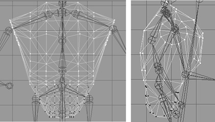
Figure 14.80
The chest vertices.
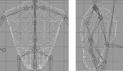
There, that’s the torso. It might not have seemed so difficult a task to you, but to me it was a nightmare! Well, maybe not that bad, but it shows you the kinds of decisions you will have to make when rigging your models. What goes where and how will it work best?
Now that we have a few nodes rigged, let’s take a look and see what they actually do.
1. If you don’t have an Anim button at the lower right, then choose Window, Show Keyframer, and make sure there is a checkmark there.
2. Click Anim to activate the Keyframer.
3. Using the Select tool in the Joint mode, select the pelvis joint (or you can use the Joints tab to make the selection).
4. Use the Rotate tool in freeform mode in the Right Side view. You will recall that freeform rotation is a simple matter of selecting the Rotate tool, clicking in the wire-frame view, and dragging the cursor left and right.
Now what you should be seeing is the entire torso, plus the head, rotate around the Bip01 Spine node. You should also see some strange things as well. The arm, leg, foot, and hand meshes don’t move. That’s because they aren’t rigged yet.
But notice that the leg bones are rotating when you rotate Bip01 Spine. Aha! I don’t know about you, but when I bend over, my legs don’t move back. Well, not unless I’m floating in water, of course. So the pelvis node, while it seems to be an obvious candidate for bending your character at the waist, looks to not be the right one.
So go back, right now, and change it. It’s simply the same procedure I showed you for the pelvis, except you do it for the Bip01 Spine1 node instead. Make sure to click the Anim button to take it out of the Keyframer first, or you won’t be able to make the changes. I’ll wait.
Musical Interlude…
There you are. Now that that’s done, go back into the Keyframer as I showed you before, and check the rotation of the Bip01 Spine1 node.
Another Musical Interlude…
Good! So everything should be working as expected now. The torso and the head meshes bend over in unison, and all the bones attached above Bip01 Spine1 bend in unison, as shown in Figure 14.81. As you’ve probably deduced, it is now a reasonably minor matter to rig the rest of the nodes. Use Table 14.2 to guide you in your rigging.
Feel free to improve on my rigging choices. Some of the joint nodes have no vertices attached, so you can use them to get finer control of the shape’s movements, if you like.
Figure 14.81
Bending at the lower spine.
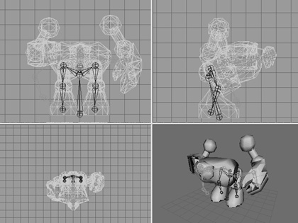
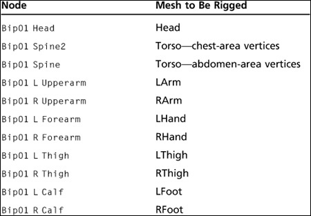
Tip
The hand meshes should attach to the forearm joints. And the foot meshes to the calf joints. Carry on.
You just need to match a mesh to a node, attach it, and move on. I’m enjoying the music here, so you go ahead and do the rest of the rigging, and I’ll sit back and relax.
Yet Another Musical Interlude…
Great! With that done, let’s move on.
Embedded Animations
Embedded animations are animations that are included with the model in the DTS file. We often use embedded animations for one-off purposes like small peculiar objects with few animations. At one time, the only kind of animation that you could export from MilkShape was embedded ones. Some modelers prefer to use them because they keep the resource’s management headaches to a minimum, because there are no separate sequence files running around the hallways making nuisances of themselves, banging the doors and getting lost in closets.
Idle Animation
The idle animation is the one used by games when the character is just standing there, doing nothing in particular. In some games you will see some pretty complex idle animation where the character scratches himself in rather inconvenient locations, looks around, scuffs his feet, and so on. We’re just going to do a basic breathing sequence so that you’ll know that the character is alive. The name for the idle animation in Torque 3D is root, so we’ll be naming our idle animation that when we export the model.
Even with a basic animation, the watchword is subtlety. Don’t overdo it.
1. Make sure the Keyframer is enabled by clicking the Anim button in the lower-right corner.
Caution
Make sure that you always leave animation mode by toggling the Anim button so that it’s not depressed, before saving or exporting any aspect of your model, even sequence files. The Anim button should only be depressed when you are actually doing animation work. Leave animation mode as soon as your animation work is finished.
2. Set the Total Frames in the Keyframer to 30. Do this in the right-hand edit box in the lower-right corner of the Keyframer (see Figure 14.82).
3. Move the slider to the first frame.
4. Choose Animate, Set Keyframe. This indicates that this particular frame is a keyframe.
5. Move the slider to the 15th frame.
6. Take note of the angle of the elbows and hands.
Figure 14.82
The Keyframer control panel.
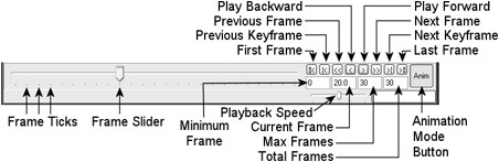
7. Select the Bip01 Spine1 node, and rotate it 5 degrees around the X-axis.
8. Rotate Bip01 R Upperarm and Bip01 L Upperarm in the opposite direction to the Bip01 Spine1 node rotation by about 5 degrees to place them back where they were before.
Tip
Whenever you change the position or rotation of a joint, you might notice that you only see the update of the animation happen in the view in which you are working. To update the other views, just click in each view once.
9. Choose Animate, Set Keyframe to set the keyframe attribute for this frame.
10. Move the slider back to the second frame.
11. Turn off the Operate On Selected Joints Only feature by choosing Animate, Operate On Selected Joints Only if there is a checkmark there in the menu.
12. Choose Animate, Copy Keyframes.
13. Move the slider to the 30th frame.
14. Choose Animate, Paste Keyframes.
15. Turn on the Operate On Selected Joints Only feature by choosing Animate, Operate On Selected Joints Only again.
Tip
From this point on, I’ll be referring to Operate On Selected Joints Only as Selected Joints, to save my lazy fingers all that cutting and pasting and also to make following along go a little smoother for you.
16. Choose Animate, Set Keyframe.
17. Save your model file!
Note
Copying and pasting keyframes can seem like an activity fraught with peril, after you’ve done it a few times and not received the results you expected.
The key is to remember to turn off the Selected Joints feature before copying the keyframe and then turn it back on again after pasting the keyframe.
Figure 14.83 shows the subtle pose difference between the 1st and the 15th frames. Use the unlink and cam nodes as your stable points of reference—they will never be moved. Now you can test your animation by clicking the Play button on the Keyframer controls. The Play button is the one that looks like a single arrow pointing to the right.
Figure 14.83
The difference in poses.
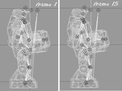
As long as the Play button is down, the animation will loop by running to frame 30 and then back to frame 1 again. If you find it runs too fast, you can change the Animation FPS number in the Preferences dialog box to a lower value to slow the animation.
Notice that when the animation is actually running, that subtle pose change becomes quite noticeable.
Tip
An excellent tool called characterFX is useful for creating animations, and it works well with MilkShape. Unfortunately, for logistical reasons it could not be included with the tools on the companion DVD. However, it does a great job of streamlining the process and is quite flexible, so a quick Google search for it on the Internet might be worth your while!
The idle animation is an example of a cyclic animation—one that repeats over and over, barring something more interesting to do. To this end, we make sure that the tail end of the animation blends nicely with the start by making the start and end frames of the animation exactly the same. That’s why we copied the keyframe from frame 1 and pasted it at frame 30.
Run Animation
The run animation is the staple of first-person shooters. Run and shoot, run and shoot. Our Hero character has a somewhat awkward lower body, which will tend to make any animation of him running look a bit goofy. Well, we’ll turn that into a feature and capitalize on that goofiness. By the way, this is another cyclic animation, so we need to make sure that the start and end frames are the same.
1. In the Keyframer, set the Total Frames to 96. Additional frames will be added after the 30 you started with for the idle animation, so that we end up with a total of 96 tick marks above the slider.
2. Move the slider to frame 31.
3. Make sure that Operate on Selected Joints Only mode in the Animate menu is not enabled.
What we are going to do next is make the start and end frames into keyframes first, before doing anything else. This ensures that they are “frozen” as they appear before any animation is done. That way MilkShape can’t interpolate the positions behind our backs.
Note
At this time, it’s a good idea to think ahead. There are a number of other later animation sequences that will require keyframes set to be identical to frame 1. These keyframes will be used as reference frames by Torque 3D for those other animations. The reference frames need to be identical to the base pose, which is frame 1. At the moment, there are no other poses and no keyframes at frames higher than 30, so all the frames up to 96 should look like frame 30, which you will recall is a copy of frame 1. And frame 1 is our base pose.
Given that, it behooves us to make those reference frames now, because it helps to “pin” the MilkShape animations in place. So once you’ve finished step 5, where you set the keyframe for frame 67, repeat that process for frames 68, 71, 74, and 77. This sets all the reference frames we will need.
4. Choose Animate, Set Keyframe. You should have a pose in frame 31 much like that shown in Figure 14.84.
5. Move the slider to frame 67. This will be the last frame in the run cycle. Now make it a keyframe by choosing Animate, Set Keyframe. You should again have the same pose as in Figure 14.84.
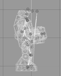
Tip
A typical run cycle has four phases: push off from one leg, land on the second leg, push off from the second leg, and then land on the first leg. Rinse, repeat.
Our run cycle has frames 31 to 67 inclusive reserved for it. That means a total of 36 frames, and it just so happens that when we divide by the four phases of the run cycle, we get exactly 9 frames for each phase! Coincidence? You be the judge.
6. Now make sure that Selected Joints mode is enabled again in the Animate menu. Move the slider to frame 40.
7. In the Right Side view, select the Bip01 Pelvis joint (it acts as our base node), and move it up about three-quarters of a grid square, as shown for frame 40 in Figure 14.85. The movement of this base node moves the entire model—it’s a transformation operation.
Note
The base node is the node to which all other nodes attach, either directly or indirectly. Some people call it the “grandpa” node, the “grandparent” node, or the “master” node. I call it the base node. In every model with a skeleton there will be a base node, and sometimes more than one. In our model one base node happens to be named Bip01 Pelvis and the other is unlink. As the chapter unfolds, I might use either the term base node or the name Bip01 Pelvis. I won’t call unlink a base node, because it only has a single child and is therefore not much a base for anything. Don’t forget this, so that you don’t get confused!
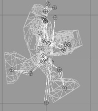
8. Select the Bip01 R Thigh node, and then in the Side view rotate it so that the leg moves forward.
9. Rotate the Bip01 R Calf node forward a wee bit as well, until the leg matches the configuration in Figure 14.85.
10. Repeat the rotations for the left leg, and move its nodes backward. In order to get things looking right, you might have to adjust the joint positions slightly by moving them, but not by much. Really try hard not to do that though. You get the best and more natural looking animation results by only rotating joints.
11. Rotate the left arm using the Bip01 L Upperarm node and the Bip01 L Forearm node, swinging them forward until the hand is approximately opposite the right leg, as shown in Figure 14.85.
12. Set frame 40 to be a keyframe.
13. Move the slider to frame 49. Use Figure 14.86 as the guide for this frame.
14. Move the Bip01 Pelvis node back down vertically to the height where it was in frame 31.
15. Move all of your legs and joints back to approximately the same configuration as in frame 31. You want the feet to be planted properly at ground level. You might need to fiddle with Bip01 Pelvis a little until you get the foot positioning on the ground right.
16. Swing the left arm down to the side of the model.
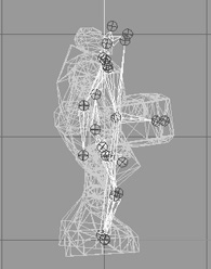
17. Set this frame (49) to be a keyframe.
18. Move to frame 58. Use Figure 14.87 as the guide for this frame.
19. Pose frame 58 the same as frame 40, except swing the legs in the opposite directions. Don’t forget to move the Bip01 Pelvis node again.
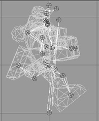
20. Swing the left arm back, and rotate the elbow so that the left hand comes up parallel to the ground.
21. Set this frame to be a keyframe.
22. Move to frame 67. Use Figure 14.88 as the guide for this frame.
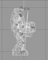
23. Swing the arms and legs back to roughly the pose they had in frame 31.
24. Set this frame to be a keyframe. Use the Play Forward button to watch the animation. If the animation seems to be too fast or too slow, change the Animation FPS setting in the Preferences dialog box until it seems right, and take note of the value you use.
Now you have probably noticed that although we set the pose in only five frames, the program automatically interpolated, or figured out, what the in-between frames should look like. Torque 3D does the same thing for us when we use the model in game. This is goodness. That’s as much of the run animation as we’re going to do here, but you should practice working with this for a while. The first place you should start is to set the keyframe in the middle of the ones we’ve already set—at frames 35, 45, 54, and 63—and adjust the leg positions to get a better animation from the legs.
Don’t try too hard to make the animation look natural though. He’s a goofy character and should have that sort of goofy, cartoonlike appearance when running.
Head Animation
This is the animation that Torque 3D automatically invokes when it needs to know how far to move your character’s head when it is looking up or down. So basically this animation’s purpose is to define limits or a boundary and not so much the movement. However, if your character’s facial or head shape would change when looking up or down, then you would create a more complex head animation.
That being said, it is really quite quickly dealt with. The animation will consist of a reference frame, an “up” frame, and a “down” frame.
1. Frame 68 is the reference frame for this sequence, and you’ve already made it so, according to the note I gave you back when we were starting out with the run animation. I hope.
2. Move to frame 69.
3. In the Right Side view, rotate the Bip01 Head joint until the head is looking up at the maximum angle you want to allow. You may also need to move the head back a bit.
4. Make sure that Operate On Selected Joints Only mode is enabled, and make this a keyframe.
5. Move to frame 70.
6. Rotate the Bip01 Head joint until the head is pointed down at the maximum angle you want to allow. You may also need to move the head forward a bit.
7. Make this a Selected Joints keyframe also.
8. Save your work! There, you are done. That’s the entire animation sequence! Check your frames against Figure 14.89 to make sure you got it all right.
Headside Animation
In the same way that the head animation defines the limits for the up and down motion performed by Torque 3D, the headside animation provides the limits for the left and right motion. This is most visible from the third-person perspective when in the game.
Do the same thing you did for the head animation, but use frame 71 as the reference frame, frame 72 for the left turn, and frame 73 for the right turn. Make each of these frames a keyframe, and save your work when you finish.
Figure 14.89
Head sequence frames.
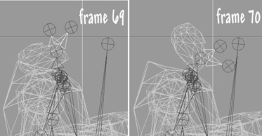
Look Animation
The look animation is basically another movement-limiting animation that defines how the character’s arms will be posed when he is looking up or down. Again, it is a simple two-frame animation that doesn’t require us to get into detail now. Frame 74 will be your reference frame. Use frame 75 for the down “look,” or aim. Make sure you have both arms positioned sensibly. Use frame 76 for the up aim. Set both as keyframes, and save your work again.
Death Animation
As you saw earlier, there are many possible ways to die. The Torque 3D demo supports 11 “standard” death animations, but you can easily add more by writing a minor code change into the server script for each player.
We’ll cover only one death animation here. We’ll have the character collapse backward and fall to the ground on his back, with his feet tossing into the air and back down again.
1. Move to frame 77, and set the pose back to resemble the resting pose as closely as you can, without spending too much time on it.
2. Set this frame to be a keyframe.
3. Move to frame 82, and rotate the arms and hands to match. You can leave the character’s head on but thrown back like I did or have it pop off temporarily. It’s your model! Let Figure 14.90 guide you.
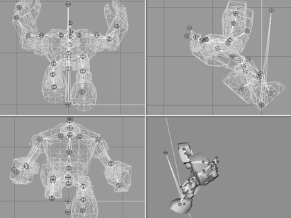
4. Set frame 82 to be a keyframe.
5. Move to frame 86.
6. In the Side view, drag the base node backward several grid squares.
7. Continue to rotate and move the arms and legs, and rotate the body around the Bip01 Pelvis node to make the body tipped past horizontal with the bottom of the torso higher than the top, as shown in Figure 14.91.
8. If you haven’t guessed it by now, make this frame a keyframe!
9. Move to frame 91.
10. The body is hitting the ground, with some momentum still in the legs. Align the bottom of the torso (which is actually the character’s back) even with the ground. Rotate the legs and knees to fling the feet up over the body, and rotate the arms to fling them beyond the head and away from the body, as shown in Figure 14.92. By now the Bip01 Pelvis node should be 10 or 11 grid squares or so behind the origin along the Z-axis, as seen in the Side view.
11. Yup, this is another keyframe. Go ahead, make its day.
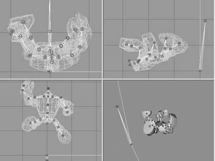
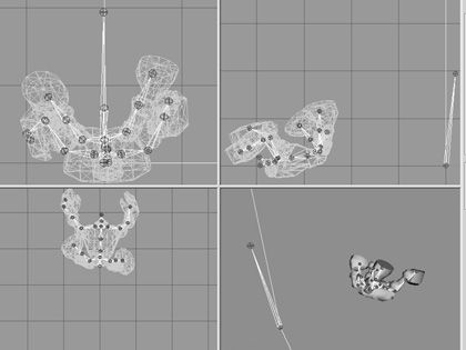
12. Now for the final resting position. Move to frame 96.
13. Lay the body out, flat against the ground. Also, move the base node one or two more grid squares farther back, to cause the body to slide along the ground. Lay the arms flat to the sides, the feet and legs down on the ground and spread somewhat. Tilt the head back. As you can see in Figure 14.93, he’s dead, Jim.
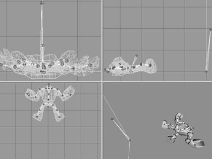
14. Keyframe him, Dano! (Okay, that’s a mighty obscure reference, I’ll admit. Indulge me!)
15. Save your work.
Well, that’s the lot of them. Enough animations to give you what you really need to know to get moving on animating for Torque 3D in MilkShape 3D. There’s still more to cover—we’re not quite out of the woods yet. Now we have to tell Torque 3D how to find the animations.
Sequences with the DTSPlus Exporter
Before starting this section, make sure you have myhero.ms3d open in MilkShape 3D. One of the nifty things about the Torque 3D DTSPlus Exporter (golly gee willikers, did I just say “nifty”?) is that you don’t have to create, type, or even remember the special materials stuff. The DTSPlus Exporter’s interface does it for you (see Figure 14.94). You just need to click some buttons, check some checkboxes, and fill in some fields. The exporter takes care of the rest.
Figure 14.94
Torque 3D DTSPlus Exporter dialog box.
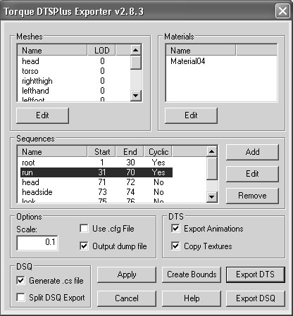
Cyclic Animations
There is something about two of the sequences that you should pay special attention to. When we created the run sequence, we set it up to span from frame 31 to 67, with each end frame set to be copies of the reference pose. And yet the sequence is defined in the special material to span from frame 31 to 66. This is because the animation is cyclic—when the last frame is reached, the animation jumps back to the first frame of the sequence.
Because frames 31 and 67 are both reference frames, they are identical. If the sequence ran to 67 and then jumped to 31, you would see a slight pause in the animation while the two identical frames are displayed.
To prevent this little hiccup, we loop the sequence at frame 66 instead of 67.
So then, you ask, why bother with the reference frame at 67? Simple—it’s so that when we are viewing the animations in MilkShape 3D, with MilkShape 3D’s interpolated frames (the ones that aren’t keyframes), they will look right.
The same principle applies for the death animation, but in a slightly different way. We can’t really know what the player will be doing when he gets killed, so we don’t want his death to begin with him assuming the reference pose in frame 77 and then getting knocked onto his keister. So we start the animation on the frame after the reference frame. This way Torque 3D can itself interpolate between whatever frame was last displayed (could have been running, walking, looking around, jumping, or whatever) and the next keyframe in the death animation, which happens to be at frame 82, so that 5 frames of the sequence can be interpolated by the engine before hitting a keyframe and being forced into a particular pose.
Let’s add the root animation sequence using the DTSPlus Exporter.
1. After saving your work, choose File, Export, Torque 3D DTS Plus Exporter. You will see the Torque 3D DTSPlus Exporter dialog box appear. Ensure that the checkbox called Export Animations is checked.
2. Click the Add button in the Sequences frame. You will get the Edit Sequence frame, as shown in Figure 14.95.
3. Fill in the fields, and set the checkboxes with the values shown in Table 14.3.
4. Click the OK button.
Right, then—that was pretty slick, huh? You’ll note that despite my earlier sidebar about leaving off the start or end frame of a cyclic animation when both the keyframes at both ends are reference frames, I didn’t follow my own advice here.
That is because with this animation, the motion is subtle enough and slow enough that it doesn’t matter. You could leave the end keyframe in the sequence or take it out. It makes no real difference.
Figure 14.95
Edit Sequence dialog box.
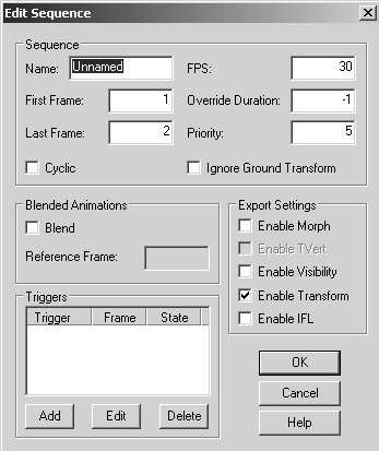
Table 14.3 Root Animation Settings
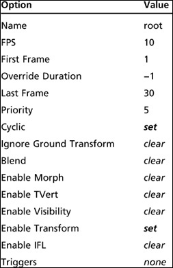
You will also notice how many more settings there are for the sequences using the DTSPlus Exporter than with the standard exporter, due to the much greater capability of the DTSPlus Exporter.
Now, with that done, go ahead and create the sequences for the running and death animations, using Tables 14.4 and 14.5 as guides.
When you are done adding all three of the sequences, click the Apply button to commit these settings to the model, followed by Cancel to make the dialog box go away. Then save your work.
Testing the Model
Whew! That’s a lot of grunt, right there. Let’s see…we’ve created a 3D model, UV mapped a texture to it, created a skeleton and rigged the vertices of the model’s mesh to the skeleton, then created a bunch of animations, and organized them into sequences.
Table 14.4 Run Animation Settings
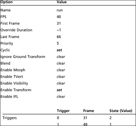
Time for a short break maybe? Okay. Time’s up—back to work!
Let’s test these things out.
A little later in this chapter, we will look in detail at the DTSPlus Exporter for Milk-Shape 3D. But for now we’ll just use the exporter in a fundamental way to get our model to work in Torque 3D.
1. After making sure you have myhero.ms3d open, choose File, Export, Torque DTS Plus. You will see the Torque DTSPlus Exporter dialog box appear.
Table 14.5 Death Animation Settings
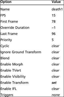
2. We’re going to take the defaults, but we should make sure they are correct. You want to have Export Animations and Copy Textures selected. Click Export DTS when ready.
3. Save your DTS file in your game folder as artshapesactorsheromyhero.dts.
That was pretty painless. Now let’s make sure the model works! We’ll fire up the Torque 3D Toolbox FPS Example we used earlier in this chapter and use the Shape Editor to check out the model.
1. Launch Torque 3D Toolbox.
2. Launch the FPS Example, Blank Room in the World Editor and then click the Shapes Editor tool, on the far right of the Editors toolbar.
3. In the Shapes tree, click the Library tab, navigate to art/shapes/actors/hero and then double-click on myhero.
4. The model should appear in the center of the screen.
5. Use the mouse actions to rotate the model and bring it closer to you or move it farther away. Right-click and drag will slide the camera around. The mouse wheel will let you zoom in and out.
6. Choose an animation from the Properties, Sequences tab.
7. Click the Play button in the controls in the lower center of the screen.
8. Check out the other sequences, but remember, the ones that don’t cycle are going to run just once and will stay at the last frame.
9. If necessary, go back to your model in MilkShape 3D and make adjustments to your animations, and then come back here to check them out.
Use the Player in Game
Now that we’ve seen that our model works in the Blank Room, let’s have a look at him in game. In this next part we’re going to substitute the standard character, Gideon, with our Hero model using the Datablock Editor and we’ll let Torque 3D manage our datablock.
1. Run the Torque FPS Example, Deathball Desert in World Editor mode.
2. Open the Datablock editor, which is the fifth icon from the left on the editor toolbar.
3. In the Datablock Library, click the New tab and then click once in the scroll bar and you’ll see the PlayerData datablock class. Double-click PlayerData.
4. In the Create New Datablock dialog, enter myhero and click Create.
5. In the Datablock properties below the library, change the name, which is currently DemoPlayer, to myhero.
6. Move the properties scroll bar down to about two thirds of the way down until you see the rollout Render and then click the ellipsis next to shapeFile in the Render section.
7. Navigate to our hero at actorsheromyhero.dts and then click Open.
8. Click the disk icon at the top of the Datablock properties area and save the new datablock. You’ll notice that the datablock is being saved to art/datablocks/managedDatablocks.cs. You will see similar kinds of files in other places, with managed this and managed that. This is the terminology that Torque 3D uses when it creates default files in which to deposit things created in Torque 3D editors.
9. In response to the Save Datablock? dialog, click Yes.
10. Now we need to change the character that appears in every one of the spawn spheres of this level. Click the Object Editor icon, on the far left of the editor toolbar.
11. In the Scene tree on the right, expand SimGroup—MissionGroup, and then expand SimGroup—PlayerDropPoints.
12. For each of the spawn spheres in this group, in the Spawn rollout, change the value of spawnDatablock from DefaultPlayerData to myhero. To do this, click the Spawn Sphere and then in the inspector area find the Spawn rollout, expand it and change the name of the spawnDatablock from DefaultPlayer to myhero.
13. Press F11 to exit the World Editor and see the character in game. Hit Ctrl-K to kill Gideon. Ugggghh. Your guy just up and dies. The view switches to an external camera, and you see the death animation.
14. Press the spacebar to respawn and then hit Tab to see your character in game.
Try out all three of the supported embedded animations. Watch them in action.
You now have an animated Hero character to use in your game. And it really isn’t that difficult to get to this point. If you are even a halfway-decent artist and have a good eye, I’m sure your model and animations are much better than mine.
A later section provides some detail into the workings of the DTSPlus Exporter for the Torque Engine. With its help, you should take some time to fiddle with settings and different animations and add your own animation sequences.
Animation Sequence Files
So far, we’ve only been able to see three of our animations in action. What about those head movement thingies? Well, in order to see them working properly as blended animations, we need to create our own sequence files.
Using Your Own Sequences
Torque DTSPlus Exporter knows how to handle animation sequences, and it’s really quite easy. Make sure you have your myhero.ms3d file open.
Once you have your animations made and sequenced, deactivate the Anim button.
Select all of your mesh groups using the Groups tab, and regroup them as one mesh. Rename the mesh so that it ends with a zero so that the exporter won’t get confused.
Now, run the DTSPlus Exporter and make sure that both the Generate cs File and Split DSQ Export checkboxes are checked. Then click the Export DSQ button. When the Save As dialog box appears, browse to 3D3EDEMOdemodatashapes actorshero, and then type hero into the text box. No extensions or anything, just hero. The exporter will append an underscore to this name and then export each sequence as its own DSQ file, with the filename being made up of “hero_” at the front, followed by the sequence’s name, which is then followed by “.dsq”. It will also create a CS script file that creates a mapping of the sequence name to the newly created sequence file for the hero.dts model.
After that you will then need to re-export your model using the Export DTS button, but this time with the Export Animations checkbox cleared, so that only the rigged model is exported. And of course you will export it to the same place you put the sequence files, replacing the hero.dts that is already there.
Now you can pop into the FPS Example, and the blended head motions will be there. You should be able to see the running, root, and death animations. A word of caution, though. You might have difficulty spotting the actual movements, because as you move the mouse in third-person mode to move the head or the whatever, your view changes at the same time. But give it a go. Under normal circumstances it would be the other players in a multiplayer game, and not yourself, that would see the animations.
Using Torque’s Sequences
Finally, you can use the sequences that came with the Torque 3D demo as the animations for your own model. There are some caveats, however. Your skeleton has to exactly match the GarageGames skeleton in all ways, shapes, and forms. The nodes have to be correctly named, and the joints need to be rotated and placed close enough to the GarageGames skeleton placements.
There is one other little wrinkle, and that is how MilkShape 3D normalizes its joints every time you place a new one. This is bad for our purposes, because it means that it is next to impossible to match the rotations of the Torque joints.
But all is not lost! I just so happen to have the Torque skeleton used for the Orc monster, and have included it in the RESOURCES folder for Chapter 14. All you need to do is remove your own skeleton and replace it with the Torque skeleton.
1. Open your myhero.ms3d model, and save it as myHeroGG.ms3d. From here on, work with myHeroGG.ms3d.
2. Go to the Joints tab, and delete all the joints, select Pelvis and press the Delete key and then do the same thing with the unlink node.
3. Open the DTSPlus Exporter, and remove all the sequences.
4. Click Apply and then Cancel. Save your work.
5. Choose File, Merge, and then browse to RESOURCESCH14 and locate and select skeleton.ms3d. Click the Open button. The skeleton will be merged with your model.
6. Next, you must modify your mesh to match the skeleton, and not the other way around. Do not touch the skeleton; don’t move its joints or rotate them or anything. Don’t add or delete anything. Just keep your hands off it! However, you will have to move, rotate, and scale the body parts to fit them to the new skeleton.
7. Now rig the mesh to the skeleton, just like you did earlier with your own skeleton.
8. Collapse your mesh groups into one group, just like we did with the embedded animations, and make sure that the single mesh name ends with a zero.
9. Save your work in a file with “onemesh” added to the filename, so that you don’t overwrite your original “final” model.
10. Using Torque 3D DTS Plus, export your model to 3D3EDEMOdemoart shapesactorsmyhero.dts. Make sure that Export Animations is not checked.
First thing we need to do is to create the animation sequence bindings. We do this by assigning the sequence files to an animation name in the TSShapeConstructor object for our model when it’s used by Torque 3D. We do this by creating a file with the same name as our exported model but with a .cs extension instead of .dts. We put our TSShapeConstructor code in this file. When the Torque 3D Resource Manager loads a .dts object, it automatically looks in the same folder that the .dts file was in for another file with the same name but with the .cs extension. It executes this file if it finds it. This means that you don’t have to worry about finding the appropriate place in your script hierarchy to exec this script file.
So that’s the file we’re going to create. Using Torsion, create a script file in your art/shapes/actors/hero directory called myhero.cs. Type the following into this file:
singleton TSShapeConstructor(myHeroDts)
{
  baseShape = "./myHero.dts";
  sequence0 = "art/shapes/actors/animations/player_root.dsq root";
  sequence1 = "art/shapes/actors/animations/player_forward.dsq run";
  sequence2 = "art/shapes/actors/animations/player_head.dsq head";
  sequence3 = "art/shapes/actors/animations/player_side.dsq headside";
  sequence4 = "art/shapes/actors/animations/player_lookde.dsq look";
  sequence5 = "art/shapes/actors/animations/player_diechest.dsq death2";
  sequence6 = "art/shapes/actors/animations/player_dieback.dsq death3";
  sequence7 = "art/shapes/actors/animations/player_diesidelf.dsq death4";
  sequence8 = "art/shapes/actors/animations/player_diesidert.dsq death5";
  sequence9 = "art/shapes/actors/animations/player_dieleglf.dsq death6";
  sequence10 = "art/shapes/actors/animations/player_dielegrt.dsq death7";
  sequence11 = "art/shapes/actors/animations/player_dieslump.dsq death8";
  sequence12 = "art/shapes/actors/animations/player_dieknees.dsq death9";
  sequence13 = "art/shapes/actors/animations/player_dieforward.dsq death10";
  sequence14 = "art/shapes/actors/animations/player_diespin.dsq death11";
  sequence15 = "art/shapes/actors/animations/player_looksn.dsq looksn";
  sequence16 = "art/shapes/actors/animations/player_lookms.dsq lookms";
  sequence17 = "art/shapes/actors/animations/player_scoutroot.dsq scoutroot";
  sequence18 = "art/shapes/actors/animations/player_sitting.dsq sitting";
  sequence19 = "art/shapes/actors/animations/player_celsalute.dsq celsalute";
  sequence20 = "art/shapes/actors/animations/player_celwave.dsq celwave";
  sequence21 = "art/shapes/actors/animations/player_looknw.dsq looknw";
  sequence22 = "art/shapes/actors/animations/player_dance.dsq dance";
  sequence23 = "art/shapes/actors/animations/player_range.dsq range";
};
Note that the name of the TSShapeConstructor object is myHeroDts. We need to name the object this way; the object name needs to be identical to the .dts filename including the extension but with the dot removed. It is not case-sensitive, but it’s a good idea to capitalize the name in roughly the same way that I’ve given you here, for readability reasons.
Take a look at this line of code from the TSShapeConstructor object.
sequence0 = "art/shapes/actors/animations/player_root.dsq root";
The string containing the path ending with player_root.dsq is the filename of an animation sequence. In this case, it’s the root animation. After that we see the word “root”. This is the name of the animation that Torque looks for internally. You can see by using this method that the animation file can be called anything. As long as it is mapped in this fashion, Torque 3D will use whatever sequence is in that animation file when it wants to do that particular animation.
Next, in our game folder, use Torsion to open scripts/client/default.bind.cs and scroll down to lines 379–380. You should have two lines that start with “//movemap.” Delete the two slashes from the beginning of both of those lines. Save the file.
Finally, in Torsion, in the Project view on the left-hand side, find the file/scripts/client/config.cs and delete it by right-clicking it and choosing Delete from Torsion’s pop-up menu. If you don’t have that file, don’t worry about it; just carry on.
Run the FPS Example to view your model running using the Torque skeleton. In the demo, try Ctrl+S or Ctrl+W to get the hero to salute or wave.
Here’s something: make sure your player is not standing at a spawn location or very close to another object. If you step into camera mode with F8, fly a little bit away from your character, and look back at it, you can see some cool things. Open the Mission Editor with F11, find the ID number of your character and record it. There will be an axis gizmo located in the center of the player’s body—the ID number will appear just above, below, or directly on the axis gizmo. Let’s pretend the number was 3802. This is your character’s avatar object ID or handle. Press F11 to leave the Mission Editor, keeping your camera pointed at your character. Then open the console using the Tilde (“~”) key and type in the following:
0001.setActionThread("dance");
Of course, you substitute the actual ID of your player object for the possibly fictitious 3802 in my example. Don’t forget that semicolon at the end, and don’t forget to press Enter after you type the semicolon.
Now quickly press the Tilde key again to make the console go away, and enjoy watching your player doing the funky chicken (well, it certainly isn’t the macarena!). Another sequence you can try is range, which shows the range of motion of the animated character.
You can open the file art/shapes/actors/hero/myHero.cs and see what the names of the sequences are on the right-hand side. For example, the line
sequence1 = "art/shapes/actors/animations/player_forward.dsq run";
tells us that the sequence name is run and the sequence file used is art/shapes/actors/animations/player_forward.dsq.
Have fun!
MILKSHAPE 3D’S DTS EXPORTERS
If you haven’t already noticed, there are actually two exporters available for getting models into Torque 3D from MilkShape 3D: the “standard” Torque Game Engine (DTS) Exporter and the “enhanced” Torque 3D DTSPlus Exporter. Both versions comes built into MilkShape 3D. The older “standard” version is much less capable and I never use it anymore. The new “enhanced” DTSPlus Exporter was created by a chap named Chris Robertson. I include details about the standard DTS Exporter here for you just in case you run into some obscure reason why you can’t use the DTSPlus Exporter. I can’t think of any reasons, but you never know.
The Standard Torque 3D Game Engine (DTS) Exporter
The Torque 3D Game Engine (DTS) Exporter dialog box (see Figure 14.96) has three groups of options, none of which normally need to be set. Option settings are not saved, so you rarely use this dialog box for more than just a means to double-check your option values. The recommended approach is to set options using special materials.
Collision Mesh
The exporter allows you to create as many collision meshes as you want. Each collision mesh must be named “Collision”; if you have three collision meshes, they will all be named “Collision”. If you do not have a collision mesh defined, you may have the exporter create one for you as either a box or a cylinder. You can also manually select an existing mesh. Player-characters don’t need a collision mesh at all.
Select the Create a visible copy of the collision mesh checkbox to make the mesh visible as well as collidable.
Figure 14.96
Torque 3D Game Engine (DTS) Exporter dialog box.
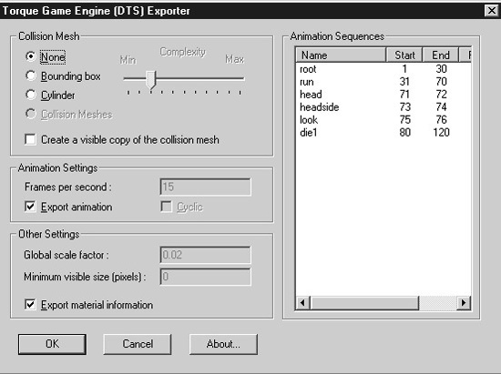
Animation Settings
The Animation Settings group displays the global values for the animations.
![]() Frames per second. This field indicates at what speed the Torque 3D Engine should play the animations. This field can be set using an Export Options material and applies globally to all animation sequences (Export Options is explained in a later section). This does not affect the number of keyframes; it simply sets the rate at which they will be played.
Frames per second. This field indicates at what speed the Torque 3D Engine should play the animations. This field can be set using an Export Options material and applies globally to all animation sequences (Export Options is explained in a later section). This does not affect the number of keyframes; it simply sets the rate at which they will be played.
![]() Export animation. If the model contains embedded animations that you want to export, then this box should be checked. No animations are exported if it is cleared.
Export animation. If the model contains embedded animations that you want to export, then this box should be checked. No animations are exported if it is cleared.
Other Settings
The Other Settings group contains miscellaneous settings values.
![]() Global scale factor. The global scale factor is the amount by which the shape is scaled when it is exported. The default scale factor is 0.1, but this field can be changed to any value set using an Export Options material.
Global scale factor. The global scale factor is the amount by which the shape is scaled when it is exported. The default scale factor is 0.1, but this field can be changed to any value set using an Export Options material.
![]() Minimum visible size (pixels). If the projected screen size of the bounding radius of the shape drops to the minimum visible size, the shape will no longer render. This is normally used to switch between different detail levels, and it’s recommended that you leave this at the default value: 0.
Minimum visible size (pixels). If the projected screen size of the bounding radius of the shape drops to the minimum visible size, the shape will no longer render. This is normally used to switch between different detail levels, and it’s recommended that you leave this at the default value: 0.
![]() Export material information. You may disable the exporting of material information (not recommended) by clearing the Export Options material information checkbox.
Export material information. You may disable the exporting of material information (not recommended) by clearing the Export Options material information checkbox.
Export Options
Materials with special names can be used to set several export options. These materials are ignored during export and are solely used to set options.
Option materials are named as follows:
opt: option, option, ...
All other properties of the material are ignored. Table 14.6 lists the available options.
There may be more than one option material. If the same options are set on multiple materials, then the last one in the material list is the value used. Here are a couple examples of valid material names:
opt: fps=10, cyclic
opt: scale=0.1
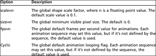
Material Option Flags
Material attributes that can be set by using the MilkShape Shininess and Translucency sliders can also be set by embedding additional flags in the material name.
Environment mapping can be controlled for the model by use of the Shininess slider—it’s the one on the left-hand side. Setting the slider to any value but 0.0 will enable environment mapping for the texture. Note that the texture you are using must have an alpha channel, which will be used to control the per-pixel shininess of the texture. Any value of the slider other than 1.0 or 0.0 will be ignored.
You can enable translucency by setting the MilkShape Translucency slider—this is the slider on the right-hand side. Setting the slider to any value other than 1.0, which is to the far right, will enable translucency for the texture. The texture you are using must have an alpha channel, which will be used by the Torque 3D Engine to control the per-pixel translucency of the texture. Any value of the slider other than 1.0 or 0.0 will be ignored.
Options that are embedded in the material name follow this format:
name: flag, flag, ...
where the : and flags are optional. Table 14.7 shows which flags are available.
A self-illuminating additive material could be called as follows:
Flare: Add, Illum
Table 14.7 Material Option Flags
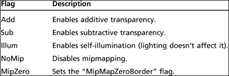
Mesh Option Flags
Meshes can have additional flags embedded in the mesh (or group) name. The mesh name follows this format:
name: flag, flag, ...
where the : and flags are optional. Table 14.8 shows which flags are available.
Here are some legal mesh or group names:
![]() leaf
leaf
![]() leaf: Billboard
leaf: Billboard
![]() leaf: BillboardZ
leaf: BillboardZ
By default, meshes do not have any flags set.
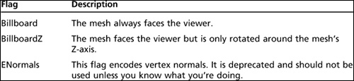
Animation Sequences
MilkShape 3D only provides a single animation timeline, but the Torque 3D Engine supports multiple animation sequences, each of which can be named and have different properties. Multiple sequences in MilkShape 3D are animated on the main timeline and are split into separate sequences by the exporter. For this to happen animation sequences must be declared, indicating where each sequence starts and ends on the master timeline. This is done through materials with special names. These materials are ignored during export and are solely used to declare animation sequences. The “Special Materials” section earlier in the chapter provides more details.
Sequence materials are named as follows:
seq: option, option, ...
All other properties of the material are ignored. Table 14.9 describes the sequence material options.
Here are some valid sequence declarations:
seq: fire=1-4
seq: rotate=5-8, cyclic, fps=2
seq: reload=9-12, fps=5
The Enhanced Torque 3D DTSPlus Exporter
The DTSPlus Exporter does not use special materials to store its extra information in. It used to, until MilkShape 3D introduced the feature of comments for objects and other aspects of a model. Now the DTSPlus Exporter maintains its settings in comment fields in the scene.
Notwithstanding that little tidbit of technical trivia, we never need to concern ourselves with the contents of the comment fields. DTSPlus provides a GUI interface in its dialog box that gives us all the access we need to the settings.
Table 14.9 Sequence Material Options
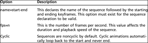
Main Dialog Box
Figure 14.94 a few pages back shows the main dialog box. Meshes and materials are added to the scene via MilkShape, and their special properties can be edited here by selecting them in their respective lists and clicking the Edit button adjoining the list.
Sequences are created, edited, and deleted via the Sequences list in this main dialog box. Again, select the sequence, and click the appropriate action button adjoining the list.
Other general settings and actions are shown in Table 14.10.
Table 14.10 General Settings and Actions
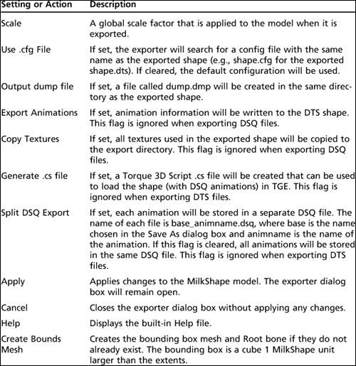
Configuration files can be used to control the export process. To use a configuration file, it must be named the same as the exported model name, except with the extension as .cfg instead of .dts. It must be in the same folder that the model file will be exported to.
Default Configuration
The exporter supports configuration files. If a configuration file is not found, the following default configuration is used:
   +Error::AllowUnusedMeshes
   -Materials::NoMipMap
   -Materials::NoMipMapTranslucent
   +Materials::ZapBorder
   +Param::SequenceExport
   -Param::CollapseTransforms
   =Params::AnimationDelta 0.0001
   =Params::SkinWeightThreshhold 0.001
   =Params::SameVertTOL 0.00005
   =Params::SameTVertTOL 0.00005
   =Params::weightsPerVertex 1
   +Dump::NodeCollection
   +Dump::ShapeConstruction
   +Dump::NodeCulling
   +Dump::NodeStates
   +Dump::NodeStateDetails
   +Dump::ObjectStates
   +Dump::ObjectStateDetails
   +Dump::ObjectOffsets
   +Dump::SequenceDetails
   +Dump::ShapeHierarchy
   NeverExport
   __mainTree
   __meshes
A “+” sets the setting to true, “–” sets it to false, and “ = ” is used to set the value of a setting.
Nodes in the NeverExport list are not written to the DTS file.
The NeverExport list is mostly used for DSQ export to exclude non-animating nodes. Names in the NeverExport list can include wildcards (*). For example, leg* will include both leg1 and leg2.
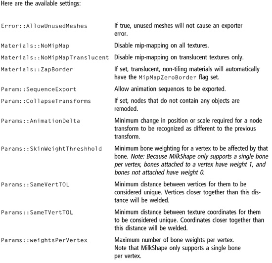
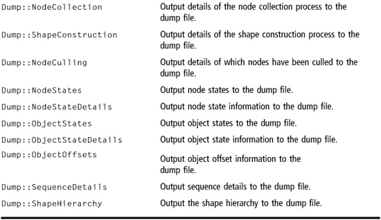
Mesh Properties
There are many extra properties that can be assigned to meshes (or groups, in Milk-Shape 3D parlance) that affect things like level of detail, billboard behavior, and visibility. To view the Edit Mesh dialog, click the Edit button adjoining the Meshes list. Table 14.11 shows these properties and their purposes.
Collision Meshes
Any mesh whose name begins with the text string “Collision” will be used in game as a collision mesh. Collision meshes are normally given a negative detail level from −1 to −8 so that they are not drawn. You can view the collision mesh in game if you need to for debugging purposes by giving it a positive detail level.
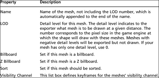
Collision meshes should use as few polygons as possible and must be convex. Try to keep the polygon count below 50 for any given model, if at all possible, as a rule of thumb.
LOS Collision Meshes
DTSPlus supports the use of special collision meshes used to do line-of-sight collision calculations. These meshes are often used for optimized operations such as checking if a bullet will hit the model. Any mesh whose name begins with the text string “LOSCol” will be used as a line-of-sight collision mesh. Normally these meshes are given a negative detail level from −9 to −16 to ensure that they aren’t rendered.
Like regular collision meshes, LOS meshes should use as few polygons as possible and must be convex.
Materials
Figure 14.97 shows DTSPlus’s Edit Material dialog box, and Table 14.12 lists its features.
Animation Sequences
You’ve already seen a sterile view of the animation sequence editor elsewhere in this chapter. Figure 14.98 shows a view of the run sequence through the eyes of the Edit Sequence dialog box.
Figure 14.97
Edit Material dialog box.
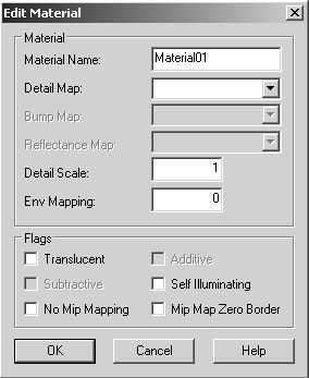
Table 14.12 Edit Material Features

As you have seen in this chapter, MilkShape 3D provides only one animation timeline. Yet the Torque 3D Engine supports multiple animation sequences, each of which can be named and have different properties. You can create multiple sequences in MilkShape 3D on the main timeline, which are differentiated into separate sequences by DTSPlus. For this to happen, animation sequences must be declared indicating where each sequence starts and ends on the master timeline using the DTSPlus Sequence Editor.
Table 14.13 shows the features of the Edit Sequence dialog box and their uses.
Figure 14.98
Edit Sequence dialog box.
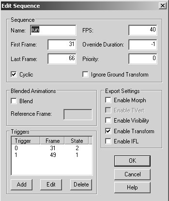
Colada
Torque 3D will import models in Colada format, which is handy because MilkShape 3D will export in Colada format, but the Colada support in MilkShape 3D is “still in its infancy,” as Rex, one of the denizens of the Torque online community puts it. You can export the mesh and materials of the model but not the skeleton. It also does not know how to label embedded animations so that Torque 3D can find them. Perhaps sometime in the future MilkShape 3D will support Colada export in a flavor that is suitable. For now you should feel comforted by the fact that DTS models load faster, support all the model characteristics that Torque 3D supports, and they are pretty close to a 1-to-1 mapping of how Torque 3D represents models in memory anyway. The main motivation for Torque 3D supporting Colada is to enable artists that use tools that do not have Torque DTS exporters to get their models into Torque 3D.
When Torque 3D imports a Colada file the first thing it does is to convert it to DTS representation and write that out to disk with the word .cached inserted in front of .dts. And it will from that point on use the cached version and not the Colada version. If you make a change to the Colada version, Torque 3D will then automatically change the cached DTS. So, I guess the point is that with using MilkShape 3D you don’t need to use Colada anyway as long as you are exporting for Torque 3D.
Table 14.13 Sequence Editor Features
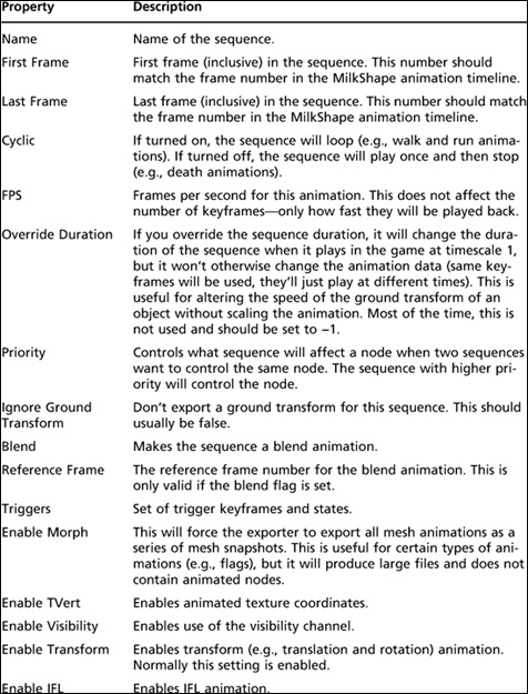
So, why all the fuss about Colada? Well, Colada is a definition of an Open Source XML schema for exchanging art between various software packages and engines. Colada files have the extension .dae, which stands for Digital Asset Exchange and pretty well all the big name graphics and modeling tools support Colada. So, it is becoming a bit of a standard in the modeling world.
MOVING RIGHT ALONG
This was a pretty busy chapter, huh? We created a character model and a texture skin for it, created a skeleton and rigged the model’s meshes to the skeleton, and then proceeded to animate the skeleton. We then learned how to use two different exporters to get the animations into Torque 3D. In fact, as you’ve seen, there are many different combinations of ways to get animated characters into Torque 3D, using embedded animations and sequence file animations and even reusing animation sequences created by other people.
It’s a lot of work, and that’s why even the smallest game development team usually has at least one modeler on board to handle that workload.
So now that you can create your own player-character, it’s time to create some sort of transportation so he can get around in the game world. That’s the subject of the next chapter, “Making a Vehicle Model.”