
3.2 Stereoscopic Display
The general framework of stereoscopic display consists of two components: a multiplexing process to encode the stereo image pair at the display side, and a de-multiplexing process to retrieve the left and right view at the viewer side. To conduct the de-multiplexing, the viewers are required to wear special glasses. In the following, we discuss different multiplexing methods used in the stereoscopic display.
3.2.1 Wavelength Division (Color) Multiplexing
The color reproduction mechanism described in classic color theory provides a method to deliver the left and right image by separating the visible spectrum (370–730 nm) into two different wavelength bands. The most common approach for wavelength division multiplexing is to multiplex the higher spectral band (red) of the left image and the lower spectral band (blue/cyan) of the right image in the display side; and the viewers can de-multiplex the signal by wearing anaglyph glasses whose left and right glass can filter different spectral information such that each eye perceives its corresponding color. Anaglyph is the least costly method of displaying 3D images wherever the device can comprise primary colors, that is paper, film, CRT/LCD. A common and simple way to generate an anaglyph image is to take the linear combination of color information from left and right image: Let the red, green, and blue information (codeword stored in image file) of one given pixel located at coordinate (x,y) in the left image as ![]() and one pixel located at the same coordinate (x,y) in the right image as
and one pixel located at the same coordinate (x,y) in the right image as ![]() , the pixel in the anaglyph image
, the pixel in the anaglyph image ![]() can be constructed through a linear combination process with one 3×6 matrix M :
can be constructed through a linear combination process with one 3×6 matrix M :
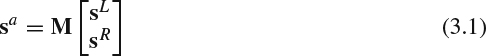
One example of the matrix is
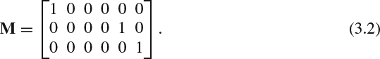
With this simple implementation, the red component of pixel sa has a value from the red component of the left image; and the green and blue color information for pixel sa are from the green and blue color channel in the right image, respectively.
The optimal solution for M by addressing the unique characteristics of a primary color system adopted in different displays and spectral response of different filter chosen in anaglyph glasses can be derived via orthogonal projection [3]. Let the display gamma function as g(·) and the gamma corrected value ![]() and
and ![]() for i = 0, 1, and 2. To facilitate our discussion, we denote the three color components of one pixel located at the same position (x,y) from left and right image as vector forms
for i = 0, 1, and 2. To facilitate our discussion, we denote the three color components of one pixel located at the same position (x,y) from left and right image as vector forms ![]() and
and ![]() , respectively. Denote di(λ), i = 0, 1, and 2, as the spectral density functions of the RGB display phosphors, and pj(λ), j = 0, 1, and 2, as the color matching functions for the selected primary colors. The spectral density for the left image and right image at wavelength λ from three color channels can be expressed as
, respectively. Denote di(λ), i = 0, 1, and 2, as the spectral density functions of the RGB display phosphors, and pj(λ), j = 0, 1, and 2, as the color matching functions for the selected primary colors. The spectral density for the left image and right image at wavelength λ from three color channels can be expressed as
When the display only shows the left image or the right image, the perceived pixel value at the jth primary is

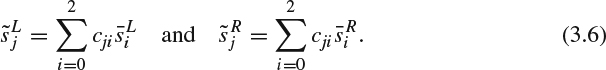
The above equations can be expressed in the matrix form by first denoting
then, bringing in (3.5) and (3.3) to (3.4), the perceived pixel value can be expressed as a linear combination of the gamma corrected pixel value as follows:
Denote ![]() and
and ![]() . We can arrive at the following matrix form for a “six primary” color system,
. We can arrive at the following matrix form for a “six primary” color system,

where [C]ji = cji.
Since the display only has three primary colors, we need to generate the anaglyph pixel sa and the corresponding gamma corrected value ![]() for i = 0, 1, and 2. Denote the three color channels as a vector,
for i = 0, 1, and 2. Denote the three color channels as a vector, ![]() . The spectral density for the anaglyph pixel sa at wavelength λ from three color channels can be expressed as:
. The spectral density for the anaglyph pixel sa at wavelength λ from three color channels can be expressed as:
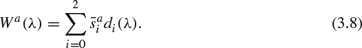
Let the spectral absorption function of the anaglyph glasses filter at left view and right view be fL(λ) and fR(λ). When the display shows the anaglyph pixel sa, the perceived pixel value at the jth primary through the left filter and right filter are

and

respectively.
To simplify the discussion, we define two constants as follows:


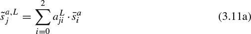
Substituting (3.8) and (3.10a) into (3.9a), the perceived left pixel value can be expressed as a linear combination of the gamma corrected pixel value as follows:
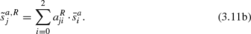
Similarly, the perceived right pixel value can be derived by substituting (3.8) and (3.10b) into (3.9b) and expressed as
Denote ![]() and
and ![]() . The perceived anaglyph image through glasses filter can be expressed in the following matrix form:
. The perceived anaglyph image through glasses filter can be expressed in the following matrix form:

where ![]() and
and ![]() . Denote the cth column of A as ac.
. Denote the cth column of A as ac.
We can formulate this anaglyph system as an optimization problem to find the optimal anaglyph image (sa) by minimizing the norm of the difference between the individually perceived image ![]() from the display excited by the original stereo image pair and the perceived image
from the display excited by the original stereo image pair and the perceived image ![]() from the anaglyph image through the glasses:
from the anaglyph image through the glasses:
In [3], an orthogonal projection method is proposed to resolve the above optimization problem. Define the general inner product for two vectors x and y as
where W is a positive-definite matrix representing the required weighting factors for different color channels.
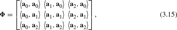
The projection can be constructed by first forming the following 3×3 Grammian matrix
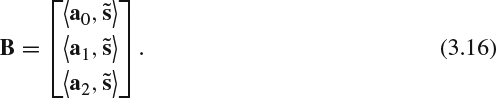
and a 3×1 matrix
The projection can be expressed as:
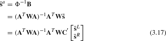
Since (ATWA)−1ATWC′ is a fixed matrix describing the characteristics of display and glasses filter, it can be precalculated after the viewing condition is settled. The optimal anaglyph image can be calculated through a simple linear algebra from the original stereo image pair.
On the other hand, the simple anaglyph approach, which allows the left eye to watch lower wavelength band and the right eye the higher wavelength band, suffers loss of color information in both eyes and causes visual discomfort known as color rivalry. In addition, the overlapped spectrum provided by three different primary colors in the display and by imperfect spectral separation filter in the glasses filter result in crosstalk between left and right channels. To alleviate these issues, one could adopt a multiple interleaved spectral band approach by dividing the spectrum into six different bands from lower wavelength to higher wavelength as [BL BR GL GR RL RR] and assigning band [BL GL RL] to the left eye and band [BR GR RR] to the right eye [4]. Each view image will be filtered by one set of multi-band filters to preserve spectral information in either [BL GL RL] or [BR GR RR] before multiplexing together in the display. The viewers' glasses should also be able to separate the different sets of multi-band information to the corresponding eye. Theoretically, having assigned complementary RGB information can improve the full color perception in left and right eyes. In practice, the quality of the perceived images depends on (a) how the spectrum is divided into multiple intervals such that each eye has its own color gamut to reduce color rivalry, and (b) how accurately designed the color filter in the display and glasses are to reduce the crosstalk. With a known spectral absorption function of the multi-band filter, it is also feasible to combine the aforementioned orthogonal projection method to construct the optimal anaglyph image.
The further improvement over the aforementioned multi-band method is proposed in [5]. The spectrum is partitioned into nine difference bands from lower wavelength to higher wavelength as [B1L B2R B3L G1L G2R G3L R1L R2R R3L]. Bands [B1L B3L G1L G3L R1L R3L] are assigned to the left eye and bands [B2R G2R R2R] are assigned to the right eye. We can merge bands B3L and G1L together as one band, and G3L and R1L as one band, which results in four different bands in the left eye. This 3–4 band filter design has the advantage of increasing the luminous efficiency and requiring no or less color correction. Note that the spectrum can be further partitioned into more bands with narrow intervals, but the simulation results show only 3–4 band filter designs achieve the optimal luminous efficiency. The main reason that using more bands won't bring better gain is that when we increase the number of bands, the number of gaps between bands also increases. Each gap will contribute to a loss of efficiency and thus the overall efficiency cannot be improved.
3.2.2 Polarization Multiplexing
Unpolarized light comprises mutually orthogonal orientations of oscillations and can be decomposed into different polarizations through differently polarized filters. Polarization multiplexing multiplexes a 3D image pair by polarizing each view with different polarized filters in the display/projector, and the viewers can de-multiplex the left and right image by wearing a glasses with correspondingly polarized filters. When the polarization projector is used, a special nondepolarizing screen is needed to maintain the state of polarization from each view during the projection.
There are two polarization methods commonly deployed, linear polarization and circular polarization. When linear polarization multiplexing is adopted, one view will be polarized horizontally and the other view will be polarized vertically. When the circular polarization multiplexing is selected, one view will be polarized in a right-hand circular (RHC) state and the other view image in left-hand circular (LHC) state. The main drawback of linear polarization is that crosstalk will increase when the difference of orientation between the viewers' glasses and the display increases, which greatly limits the freedom of viewers' head movement and rotation. Besides, when the viewers turn their heads away from the screen, the viewers will observe the brightness of the image becoming darker and darker until finally the viewers can't see anything. This problem can be significantly alleviated by choosing the circular polarization method. However, the manufacturing cost of circular polarization filters is higher than for linear polarization.
To deploy the circular polarization method in the consumer LCD TV market, the patterned retarder (PR) technology has been introduced. This adds a patterned retarder sheet over the 2D LCD panel by employing a lamination process. This patterned retarder consists of rows of retarders that are aligned with the rows of the LCD panel. The odd rows are polarized in one state and retarded to a RHC polarized state. The even rows are polarized in the direction orthogonal to the odd row and retarded to a LHC polarized state. The patterned retarder technology was developed using glasses in the earlier years with higher manufacturing cost. The cost is reduced by using film material as film-type patterned retarder (FPR) recently. The input to the screen interleaves the left view and right view vertically such that the odd rows show the left image and the even rows show the right image. The viewers can observe left view and right view simultaneously with passive polarized glasses. One noticeable disadvantage of deploying PR via interleaving views is the reduction of vertical resolution.
Since polarization does not band-limit the color spectrum, polarization multiplexing based method can provide full color reproduction. However, the polarization filter will block a large amount of light such that the viewers can observe the lightness is significantly darker when they wear the polarization glasses. To overcome this problem, the polarization display needs to increase its brightness to compensate this brightness difference and potentially the 3D content may need brightness adjustment during the mastering process to match the brightness of the corresponding 2D version.
3.2.3 Time Multiplexing
The time multiplexing approach is to display the left view and right view image interleaved along the time domain at the display side. At the viewer side, the users need to wear shutter glasses (such as liquid crystal shutter (LCS) glasses) which can switch on and off to let the corresponding image pass through. Suppose the display has frame refresh rate F frames per second (fps); and equivalently the display can show F different images in one second. The left view and the right view image belonging to one stereo image pair can be displayed alternately. Synchronization signals indicating the time instances are needed to pass to the shutter glasses [6]. With those timing signals, the left eye of the shutter glasses will let the light pass through when the display shows the left image and block the light when the display shows the right image. The right eye of the shutter glasses will perform the opposite operation by blocking the light when the display shows the left image and letting the light pass through when the display shows the right image. Ideally, time multiplexing approach can provide the full spatial resolution and full display color gamut.
The normal film frame rate is 24 fps. We can divide one second into 24 time slots. In each time slot t, we display one stereo image pair with left view image L(t) and right view R(t). The minimum frame refresh rate for time-multiplexing 3D display should be at least 48 fps to display both views properly. Intuitively, one could display the stereo video with the order L(0), R(0), L(1), R(1), L(2), R(2), …, L(23), R(23) sequentially at 48 fps. However, it has been observed that this displaying order can cause motion confusion. This is because the left eye and the right eye need to be able to see the motion appearing at the same time. The time-multiplexing method offsets the motion timing and the parallax changes. The motion confusion problem can be alleviated by flashing the stereo image pair several times in each time slot (i.e., 1/24 second) with a display capable of much higher frame refresh rate. For example, the “double flash” system will show the stereo image picture in the order of L(0), R(0), L(0), R(0), L(1), R(1), L(1), R(1), L(2), R(2), L(2), R(2),…, L(23), R(23), L(23), R(23) sequentially at 96 fps; and the “triple flash” system will show the stereo image picture in the order of {L(t), R(t), L(t), R(t), L(t), R(t), for t = 0, 1, …, 23}, sequentially at 144 fps. Field testing has shown that triple flash surpasses the fusion threshold for much smoother motion and can provide smaller phase difference between the left and right images.
Note that the active shutter glasses needs a battery set to perform the switching mechanism and a wireless interface to synchronize it with the display, which often results in a bigger and heavier glasses frame and causes more inconvenience during viewing. In addition, halving time to let light pass through the shutter glasses reduces the perceived brightness, which needs brightness correction on either the 3D display side or the post-production of the 3D content creation stage. Supporting higher frame rate (≥120 fps) to reduce flickering and motion confusion is often required, but this requirement often poses a higher design and manufacturing cost in both the display and shutter glasses hardware. Since the response time of the liquid crystal has sample-and-hold characteristics, it is important to select liquid crystal material with fast response time and to design the switching and synchronization mechanism in the shutter glasses to alleviate the potential crosstalk caused by partially on/off during the on-off transition period [7]. Other design constraints on the shutter glasses, such as low voltage, low power consumption, and low cost, also affect the deployment of time-multiplexing based display.
For the projection applications, the wavelength division multiplexing and polarization multiplexing method normally need two projectors, which often consume more energy than a single projector and suffer pixel alignment problems from two different physical locations of the projector. One can build a hybrid system by bringing the additional time multiplexing method into the wavelength division multiplexing and polarization multiplexing system. The hybrid system can use only one projector with a switching mechanism in front of the projector to alter the desired filter used by the left and right view at different time instances.
Stereoscopic projectors enable the deployment of immersive virtual reality environments, which provides an interactive environment for users to experience a virtual 3D world. Cave automatic virtual environment (CAVE) is one of the systems providing virtual reality [8]. The system is set up inside a room, and several 3D projectors project 3D images to several walls around the room. With the detection of the user's position and viewing angle, the 3D projectors can be made to display the required content, and the perceived content can be de-multiplexed by head-mounted 3D glasses worn by the user.