
7.1 3D Artifacts
3D artifacts are the distortions introduced during the whole content production and consumption pipeline [2, 3]. Those artifacts degrade the perception of 3D content and should be removed or alleviated as much as possible at each stage of the 3D pipeline. In this section, the artifacts induced at the stage of coordinate transformations from the real 3D world coordinate to the camera coordinate and from the camera coordinate to the display coordinate are discussed. Thereafter, artifacts induced by the different 3D camera settings and display designs are introduced. Besides, the artifacts induced during the content distribution process, such as compression and transmission, are addressed. At the end, the artifacts generated by the synthesis of new views are introduced when advanced 3D video coding technologies are involved.
7.1.1 Fundamentals of 3D Human Visual System
As discussed in Chapter 3, there are mainly two different categories of depth cues for the human to perceive depth, namely, monocular and binocular. Binocular cues, which require both eyes to perceive, are the fundamental design elements along the whole 3D content consumption pipeline. Figure 7.1 illustrates how the brain constructs binocular vision. The horizontal distance between the left and right eye is known as the interocular distance. By a given observed object, for human visual system (HVS) to perceive the depth, 3D points in the world are projected onto each eye's retina. Note that the projected location of the 3D points on each eye's retina is not necessary the same. The distance between the projected location of the 3D points to the corresponding eye's fovea can be measured respectively. The difference between the two projection distances is called the retinal disparity, which is the key information for human brains to construct binocular vision. A pair of projected locations is called “corresponding” when they have the same distance, that is they have zero disparity. When HVS looks at an object of interest, for example the A point in Figure 7.1, the optical axes of both eyes converge at this object. Those convergence points do not produce any retinal disparities as they are projected to the corresponding location at each eye. A curve connecting all 3D convergence points which are corresponding in the retina is called the Horopter or Vieth-Muller circle. As shown in Figure 7.1, A, B and C are points in the Horopter circle. Points between the Horopter circle and the eyes result in a crossed disparity, and points behind the Horopter circle result in an uncrossed disparity. Points which are far away from the Horopter circle, for example the D point, cannot be fused by human brains for binocular vision and cause double images, known as diplopia. The region around the Horopter circle containing points which can be fused by HVS is called Panum's fusional area. [4]
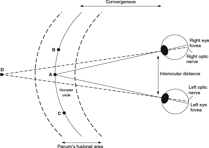
Figure 7.1 Principle of stereoscopic fusion and retinal disparity.
7.1.2 Coordinate Transform for Camera and Display System
To reproduce objects in the 3D world using camera and display systems, the afore-mentioned HVS principle should be followed. However, there are some differences between the real 3D experience and the capture-store-reproduce system. To understand the difference, the current existing camera and display systems should first be evaluated. There are two common stereoscopic camera configurations regarding how the optical axes are placed between two shooting cameras. As shown in Figure 7.2a, the first type is the toed-in camera configuration where the optical axes of both cameras intersect at C with an angle θc. A point of convergence is selected by a joint inward-rotation of the left and right cameras. The image sensors of both cameras are directed toward different image planes, which causes a trapezoidal shape of picture in each view. The second type of the camera configuration, as depicted in Figure 7.2b, is the parallel camera configuration where the optical axes of both cameras are kept parallel. A plane of convergence is constructed by a small sensor. The A point in the 3D world is captured by the left camera at the location SAl and the right camera at the location SAr. SAl and SAr are not necessary the same in the coordinate of each camera. Figure 7.3 illustrates the geometrical relation of the reconstructed 3D points in the 3D display system. SAl and SAr are shown at the point DAl and DAr respectively in the display coordinate. When the viewing distance is Zd, the left eye sees DAl and the right eye sees DAr in order to reproduce the sense of 3D perception of A. Then, A is reconstructed and fused by both eyes to have a depth Zv. Note that in the real 3D world, eyes focus on the point of interest. In the camera-display pipeline, the point of interest is shown in two different locations in the screen of the display as a pair, and eyes find the convergence points through those pairs and fuse them together to generate the depth perception of the world.
The reconstructed 3D points can be perceived in front of the display when the location belonging to the left view (DAl) is on the right side of the location belonging to the right view (DAr). This setting is called as negative parallax or crossed parallax. The perceived point can be on the display where both pixels, for example DAl and DAr, are on the same location. This is known as zero parallax. The perceived points can be in the back of the display when the location to the left view (DAl) is on the left side of the location to the right view (DAr) This is called positive parallax or uncrossed parallax. When the distance between both locations on the display is larger than the eye separation, there is no convergence point and the divergent parallax is formed. There four different types of parallax are shown in Figure 7.4.
There are several coordinate transformations involved inside the capture-display pipeline as shown in [5]. The first coordinate transformation is to convert a 3D point in the world coordinate to the corresponding point captured by the cameras in the respective camera coordinate. The coordinate transformation varies according to the type of camera configurations. The second coordinate transformation is the conversion from the camera coordinate to the display/screen coordinate, which is normally a magnification/scaling factor when both systems have different pixel resolution. The third coordinate transformation is to convert the display coordinate to the HVS observed coordinate, which depends on several factors including the size of the display, the distance between two eyes and the display, and the distance between two eyes. The coordinate transformations will be discussed in more detail in the following paragraphs.
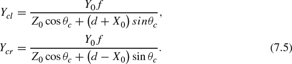
The transformation from the real world to the camera coordinate is illustrated in Figure 7.2. For a point A = [X0, Y0, Z0] in the 3D world, its captured position [Xcl, Ycl] in the left camera coordinate and its captured position [Xcr, Ycr] in the right camera coordinate are interesting to know. In Figure 7.2, 2d is the distance between two camera centers, f is the camera lens focal length, h is the axial offset from the sensor to the camera center which is only for the parallax camera configuration, and θc is the camera convergence angle which is for the toed-in camera configuration only. The angle θn between the line ![]() and the central axis can be computed as:
and the central axis can be computed as:
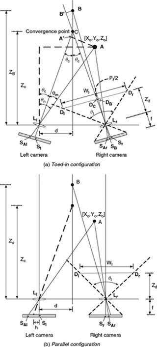
Figure 7.2 (a) Toed-in stereoscopic camera configuration. (b) Parallel stereoscopic camera configuration.
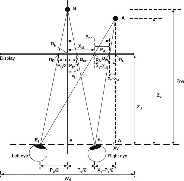
Figure 7.3 3D points reconstruction in stereoscopic display.
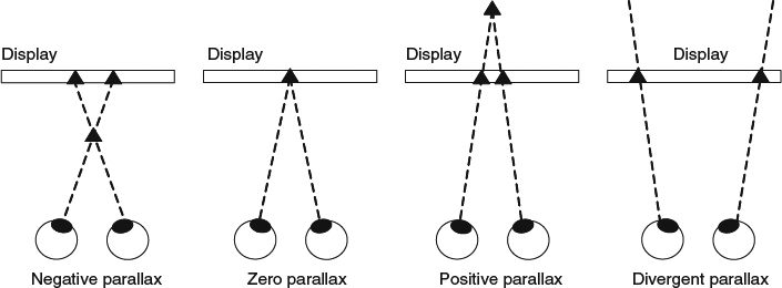
Figure 7.4 Different types of parallax.
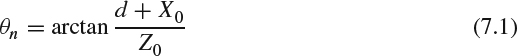
Then, the angle θm between the line ![]() and the line
and the line ![]() is the same as the angle between the line
is the same as the angle between the line ![]() whose length is Xcl + h and the line
whose length is Xcl + h and the line ![]() whose length is f and θm = θn − θc. The following triangular equation exists:
whose length is f and θm = θn − θc. The following triangular equation exists:

This can be rearranged to get Xcl as:

Similarly, for the right camera, Xcr can be computed as

Ycl and Ycr can be expressed as:
Denote Zd as the viewing distance between the eyes and the display, and Wd as the display width. A virtual display, which is back-projected from the camera system to a plane with the viewing distance Zd, can be constructed as the line ![]() in Figure 7.2. Let Wl be the width of this virtual display. The coordinate transformation from the camera coordinate [Xcl, Ycl] and [Xcr, Ycr] to the display coordinate [Xdl, Ydl] and [Xdr, Ydr] is simply to apply a magnification factor
in Figure 7.2. Let Wl be the width of this virtual display. The coordinate transformation from the camera coordinate [Xcl, Ycl] and [Xcr, Ycr] to the display coordinate [Xdl, Ydl] and [Xdr, Ydr] is simply to apply a magnification factor ![]() .
.
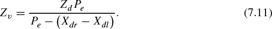
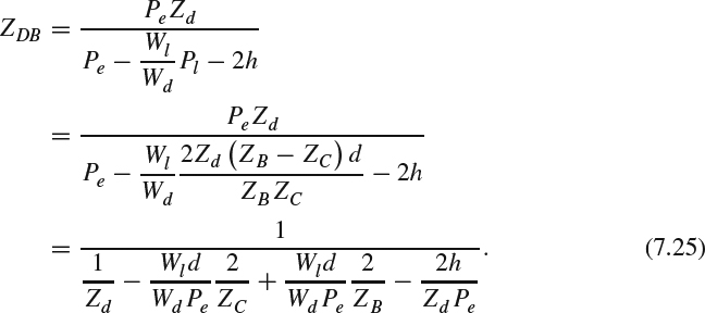
The coordinate transformation from the display coordinate [Xdl, Ydl] and [Xdr, Ydr] to the viewing coordinate [Xv, Yv, Zv] can be constructed in the following manner. Pe denotes the distance of eye separation. As illustrated in Figure 7.3, the following triangular equation holds:
Thus,
This equation can be rearranged as:
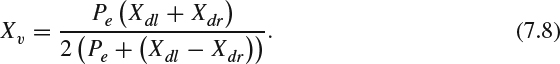
Similarly, the following triangular equation can be obtained:
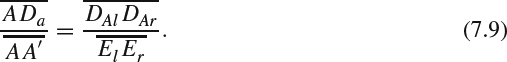
Bringing in the numerical values, (7.9) becomes:
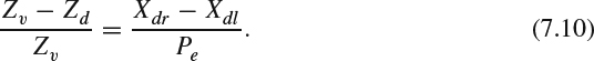
After rearranging (7.10), the depth in the viewing coordinate is:
For Yv, two points, Yvl and Yvr, can be derived as:
In the parallel camera configuration, where θc = 0, Ycl = Ycr from (7.5). Consequently, Ydl = Ydr. Substituting those results into (7.12), these two points Yvl and Yvr become a single point Yv.
7.1.3 Keystone Distortion
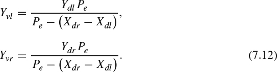
In the toed-in camera configuration, the resulting images have the shape of a trapezoid, and the oppositely oriented trapezoidal shape picture may introduce incorrect vertical and horizontal parallax. As observing (7.12), Yvl is not equal to Yvr when θc ≠ 0. Both eyes do not see the same point and the brain needs to fuse them together. The difference between these two points creates vertical parallax, which may cause viewing discomfort. Furthermore, Yvl and Yvr are functions of X0 for a given fixed Z0. In other words, the vertical offset varies according to the horizontal location. This distortion is the well-known keystone distortion [5, 6], as illustrated by Figure 7.5. For a given picture with a regular grid, the grid on the left side of the left-view image is larger than the other side. The right-view image shows opposite distortion as the left side of the grid is smaller than the other side. The keystone distortion is most noticeable in the image corners. During the shooting process, the degree of the distortion increases when (1) the distance between two cameras increases, (2) the convergence angle increases, and (3) lens focal length decreases.
Figure 7.5 Keystone distortion.
7.1.4 Depth-Plane Curvature
As shown in (7.11), for a given fixed Z0, ZV is a function of X0. In other words, an object with a fixed depth in front of the camera can be perceived with different depths according to its relative horizontal location. The corner of the image looks further away from the eyes than the center of the image does. This kind of incorrectly introduced horizontal parallax in the toed-in camera configuration is known as depth plane curvature [5, 6].
7.1.5 Shear Distortion
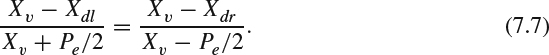
Besides the aforementioned distortion, [3, 5, 7] have described how the viewers may experience shear distortion when they have sideways movement in front of the display. Assume that the observer moves toward the left-hand side by a distance ΔP, (7.7) can be modified to:

which can be rearranged as:
The perceived point moves toward the right direction. In other words, if the observer moves his/her viewing position, he/she notices that objects with positive parallax (i.e., the A point) move in the opposite direction from his/her movement. Equations for objects with negative parallax can be derived in a similar fashion and the observer notices that objects with negative parallax have the same direction as the movement. This viewing experience contradicts the experience that users have in their daily life since the objects remain stationary in their daily life. Woods et al. [5] described how shear distortion may result in a wrong perception of relative depth and observers' motion may cause a false sense of the object motion. This problem can be resolved when a head tracking system is deployed to display a correct view when an observer moves.
7.1.6 Puppet-Theater Effect
The puppet-theater effect is a geometric distortion making human characters look small from the perceived video and thus those people look like animated puppets. Although this artifact is not clearly defined, Yamanoue et al. [8] approximately explained it using a simple geometrical calculation. Similar to the analysis done in the previous section, the viewing distance between the cameras and display system is analyzed. In the camera system, the point B is used in Figure 7.2a to explain this effect. Let DB and DC be the captured positions in the virtual display represented with the line ![]() with a viewing distance of Zd, The distance between DB and DC is Pl/2. B′ is the projected point of B onto the line
with a viewing distance of Zd, The distance between DB and DC is Pl/2. B′ is the projected point of B onto the line ![]() . ZB and ZC are the depth of B and C to the camera, respectively. The following triangular equation holds:
. ZB and ZC are the depth of B and C to the camera, respectively. The following triangular equation holds:
Substituting the value of each line into (7.15), the equation becomes:
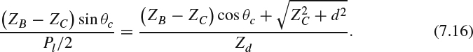
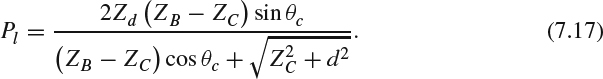
This can be rearranged to get the value of Pl as:
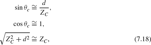
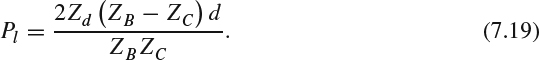
In the normal shooting condition, d is much smaller than ZC, and θc is very small, so the following approximations can be applied:
and Pl can be approximated as:
The reconstructed point B is considered in the display system (Figure 7.3). Let El, Er, and E be the position of the left eye, the right eye, and the mid point between the eyes, respectively. The lines ![]() and
and ![]() intersect the display plane at DBr and DE. The length of the line
intersect the display plane at DBr and DE. The length of the line ![]() is PB/2. The depth from B to the eyes is ZDB. The following triangular equation holds:
is PB/2. The depth from B to the eyes is ZDB. The following triangular equation holds:
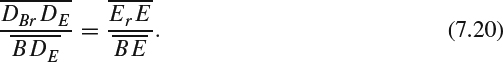
Bringing in the length of each line, this becomes:
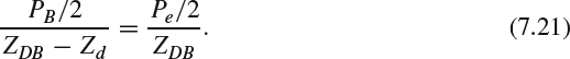
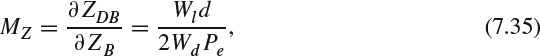
The perceived depth of the reconstructed point B is:
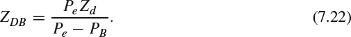
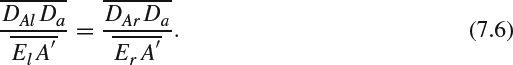
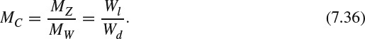
The camera-display reproduction magnification factor can be expressed as:
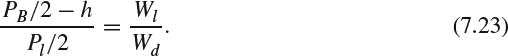
Thus,

Bringing in Eqns (7.24) and (7.19), (7.22) becomes:
For a toed-in camera configuration, where h = 0, the depth can be expressed as:
For a parallax camera configuration, ZC is infinite. Assuming h = Pe/2, the equation can be further approximated as:
Denote Wo as the real size of an object around B, Wp as the object size projected on the virtual display, Ws as the size shown on the display, and Wv as the size perceived by the eyes. From Figures 7.2 and 7.3, the size in different coordinate can be transformed as follows:
Thus,
This magnification factor between Wv and Wo can be further defined as:
For the parallel camera configuration, the magnification factor can be simplified by bringing in (7.27) to (7.30) as follows:
The perceived object size is a function of the camera separation and the eye separation.
For the toed-in camera configuration, the magnification factor can be simplified by bringing in (7.26) to (7.30) as follows:
Yamanoue et al. [8] conducted subjective testing to confirm the size magnification factor in puppet-theater effect for both camera configurations.
7.1.7 Cardboard Effect
Shimono and Yamanoue et al. [8, 9] described the cardboard effect as an artifact that the objects look flattened, without different depth shown on the surface. The cardboard effect makes objects look like standing cardboard cutouts placed at different depths. The effect generally happens when the shooting target is far away and the convergence point is set at the shooting target. This effect is also not clearly known yet, but can be approximately explained by some geometrical calculations.
Let ΔZ0 be the changes in the real depth of an object around B, and ΔZV be the changes in the depth perceived by the eyes. The reproduction magnification factor in the depth changes can be defined as:
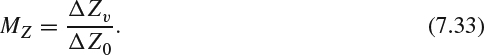
The depth changes can be observed through an object with finite length. Thus, the gradient magnification can be defined as:
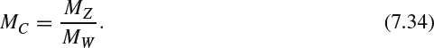
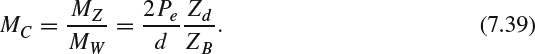
For the parallel camera configuration, MZ and MC can be calculated from (7.27) as:
In this case, the cardboard effect is related to the ratio between the viewing angle and camera len's field of angle.
For the toed-in camera configuration, MZ and MC can be calculated using (7.26) as:
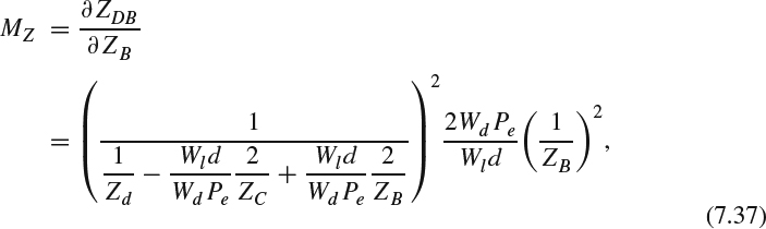
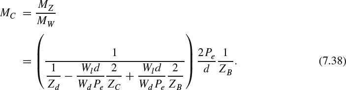
We further assume that the shooting target is near the convergence point, namely, ZB = ZC. Then, MC can be approximated as:
With the aforementioned assumption, the cardboard effect in the toed-in camera configuration is related to the distance between the two eyes, the distance between the stereo cameras, and the viewing distance between the eyes and the display. Yamanoue et al. [8] conducted a subjective testing to confirm the size magnification factor in the card-board effect.
7.1.8 Asymmetries in Stereo Camera Rig
Due to the finite mechanical accuracy of manufacturing stereo cameras, the stereo image pair may not be aligned precisely as the originally designed configuration, that is, the toed-in or parallel configuration. The focal length may differ between the cameras after manufacturing and they may not synchronize with each other when the focuses of the two cameras are readjusted during shooting, which causes different depth perception. Lenses in the cameras also suffer radial distortions and chromatic aberration. The main cause of chromatic aberration is the refraction index of the lenses and is a function of the wavelength. Different wavelengths of light have different focal points, which causes color fringes around object edges. Synchronization of shooting is also important, to make sure that the scene is captured at the same time. Asymmetries in the stereo cameras generally result in additional geometrical distortion, such as vertical parallax, and causes visual fatigue. To alleviate the geometrical distortion from internal stereo camera manufacturing factors, a calibration process is needed to make sure that the left and right cameras perform as closely as possible.
Smolic et al. [10] described how the asymmetries of color, luminance, and contrast in the cameras also bring binocular rivalry. Pastoor et al. [11] discussed how eye strain and visual fatigue are often the consequence for significant colorimetric asymmetry. Asymmetries on luminance and contrast cause time delay in the obscured eye, resulting in unwanted parallaxes along the movement direction of the cameras or subjects, and this affects the 3D perception. In addition, Mendiburu et al. [12] showed that those asymmetries degrade stereo video compression efficiency. Zilly et al. [13] proposed that those asymmetries should be corrected and alleviated as much as possible during the post-production stage via primary and secondary color correction.
7.1.9 Crosstalk
As discussed in Chapter 3, crosstalk is a major concern in 3D display. Crosstalk is caused by imperfect separation of the left and right view images such that each eye not only perceives its corresponding view but also the other view. Daly et al. [14] discussed how crosstalk can be perceived in several forms of artifacts according to the magnitude of leakage, disparities, contrast, and the affected areas of the image. For mildest crosstalk distortion, the observers can see a hardly visible halo associated with edges. When the disparities of the objects between the left and right image increase, the severity of the crosstalk becomes worse and even possibly induces double edges. With higher amplitude of leakage and higher disparities, the crosstalk may induce a ghost effect in the perception, which distracts the stereoscopic fusion and changes the perceived depth of objects. The extreme case of crosstalk is the pseudoscopic (reversed stereo) image where the left eye sees the image representing the right view and the right eye sees the image representing the left view. From a viewing experience point of view, crosstalk may make observers feel annoyed or uncomfortable, and they may experience stereoscopic depth breakdown.
7.1.10 Picket-Fence Effect and Lattice Artifacts
Autostereoscopic displays based on the parallax barrier technique (see Chapter 3) use a black mask between columns of pixels in the LCD display to control the light emitted to each eye. From some viewing angles, the observer may notice interleaved brighter and darker stripes (as vertical banding) caused by the black mask [15]. For a slanted multi-view system (see Chapter 3), the visible subpixels in each view are not in a regular orthogonal grid and each view may be perceived at different subpixels located in different positions. The observer may feel different brightness across neighboring subpixels and feel that they are perceiving objects through a lattice.
7.1.11 Hybrid DCT Lossy Compression Artifact
The lossy 3D video codec also introduces coding artifacts that affect the final perceived video quality. Before entering the whole video encoding process, each image in RGB color space is first converted to YCbCr color space to de-correlate color redundancy and then the chroma part (Cb and Cr) is further downsampled from 4:4:4 format to either 4:2:2 (half resolution in horizontal direction only) or 4:2:0 (half resolution in both horizontal and vertical direction) format. Part of the chroma information will be lost during this downsampling process, and missing values will be regenerated via upsampling in the decoder side. New colors may be generated via the interpolation from the decoded chroma samples and may cause noticeable unwanted colors.
As discussed in Chapter 5, most state-of-the-art 3D video compression codecs depend on the hybrid block-based motion-compensated DCT technology. In the ideal video encoding process, the procedure which loses information and introduces distortion is the quantization process of the DCT coefficients, which represent the magnitude of spatial frequency. Yuen et al. [16] described how the quantized DCT coefficients may introduce several coding artifacts.
- As the DC DCT coefficients represent the average value for each block, different reconstructed DC values among neighboring blocks have brightness discontinuity along the block boundaries and may bring tiling/blocking artifacts.
- When the bit rate of the compressed bit stream is constrained by the limited communication bandwidth or storage size, high frequency DCT coefficients are often quantized by larger quantization step sizes and thus the reconstructed values are often zero or with higher distortion. Under this scenario, ringing artifacts are often observed around sharp edges in the reconstructed images.
- The quantization on low frequency DCT coefficients also introduces some level of detail loss and causes blurring artifacts. The blurring artifact in the chrominance component will be observed as smearing of the color between areas of different color, which is well known as the color bleeding artifact. False edge artifact can be introduced for inter-frame coding because the highly quantized DCT coefficients cannot compensate for the block boundary discontinuities in the reference frame. The loss of details from quantizing DCT coefficients may also make a smooth area look like partitioning the whole area into multiple bands with contours along the band boundaries, which is well known as the false contouring/banding artifact. Owing to the design of 2D DCT basis images, which are often horizontally or vertically oriented, staircase artifact is also observed along the diagonal edges and features [17].
Motion estimation and motion compensation is one of the key factors to significantly improve the video coding efficiency. However, the true motion vector related to one block in the current frame may not be found in the reference frames. The corresponding block will have high prediction residual and the coding efficiency is degraded. The consequence of this failure may introduce visible distortion as padding the mismatched block from the reference frame to the current block location, which is often known as motion compensation mismatch. The ringing and motion compensation mismatch together bring mosquito noise, which is often observed as fluctuations of different color components in the highly contrasting edges or moving objects. In addition, stationary area temporal fluctuation is observed in the smooth area owing to different selected coding modes/parameters in the same area along the temporal domain. With a scene containing high motion, motion judder artifacts may be observed, owing to the temporal aliasing without sufficient sampling rate along the time domain. Advanced displays with high frame rate motion compensated methods could alleviate this artifact.
7.1.12 Depth Map Bleeding and Depth Ringing
When the depth map is compressed using the hybrid block-based motion-compensated DCT codec, the depth map suffers the same artifact as the 2D color images. Furthermore, those 2D artifacts may affect the final perceived depth after the DIBR rendering process. The blurred reconstructed depth map may bring depth bleeding between foreground and background. The ringing artifact in the depth map causes depth ringing in the perceived image.
7.1.13 Artifacts Introduced by Unreliable Communication Networks
Owing to the unreliable nature of the communication networks, the compressed 3D video streams may suffer packet loss or bit corruption, as discussed in Chapter 6. Because the state-of-the-art 3D video codecs explore the view-spatial-temporal redundancy, the encoded streams exhibit strong dependency on the previous decoded syntaxes and reconstructed contexts (see Chapter 5). Therefore, having corruption of some bits or losing packets results in the following successful received packets/bit streams being undecodable and degrading the final reconstructed 3D video. For real-time playback, packet delays may cause display jitter along the time domain when they miss the targeted display time. The details of the aforementioned issues will be discussed in Chapter 8.
7.1.14 Artifacts from New View Synthesis
As discussed in Chapter 5, advanced 3D video codecs adopt a view synthesis method to generate the required views. For the scenarios using the DIBR technology, the major problem is the newly exposed areas appearing in the synthesized views. Hole-filling algorithms are needed to assign values for those areas. Several techniques, including preprocessing and post-processing discussed in Chapter 5, are still imperfect and may suffer artifacts such as false depth distortion and nonmatching textures between eyes in those newly filled regions, which cause binocular rivalry [14].
For a free viewpoint 3D video system, because a new view is synthesized from other views without extra information, it is expected that the free viewpoint system will exhibit some other unique artifacts. According to the capturing environment, the artifacts can be categorized as constrained on unconstrained artifacts [18]. When camera parameters can be calibrated precisely in a highly constrained environment such as a camera studio, visual artifacts in view synthesis arise principally from an inexact geometric representation of the scene. The artifacts can be further categorized into global errors and local errors. The global errors take place in the gross shape including phantom volume, phantom protrusion, and hole. The local errors are shown in the exact surface, position including sunken or raised surfaces, and blurring. Ambiguity in shape caused by occlusion may produce phantom volume or phantom protrusion. Areas incorrectly marked as background induce holes on the visual hull. The undetermined surface coming from ambiguity in the stereo analysis for a region due to lack of structure or repeating patterns results in a sunken or raised surface. Limitation in surface placement precision and image resolution may blur the final result when blending multiple images.
For the scenario where the lighting conditions and background are not constrained, such as a football stadium, the videos may have different resolution and levels of motion blur. The camera parameters need estimation or correction from the captured video sequences. The ambiguity in the input data and the inaccuracies during calibration and matting cause significant differences between the reconstructed view and the original true view. In the unconstrained scenario, the errors can be further classified as errors in shape and errors in appearance. Errors in shape appear in the areas where a synthesized image misses a foreground element or contains an extraneous foreground element when compared to the ground-truth image. Errors in appearance occur when a region in the synthesized image contains different pixel values to a region in the ground-truth image. This can happen through the rendering of the incorrect surface or due to incorrect sampling of the input image.
7.1.15 Summary of 3D Artifacts
Before creating the objective quality estimation metric for 3DTV, the first step is to identify the unique 3D artifacts, which could arise in various usage scenarios involving stereoscopic content. In the previous sections, the common artifacts are discussed. Additionally, Boev et al. [2] provide a summary of possible artifacts in each stage of the 3DTV processing pipeline including content creation, compression, delivery, and consumption. Table 7.1 presents the summary of the artifacts for each stage. The noise can be categorized as structure, color, motion, and binocular. Structure represents those artifacts that will affect human perception of image structure such as contours and texture. The color and motion rows represent artifacts that affect the color and motion vision, accordingly. The binocular row represents those artifacts that affect the stereoscopic perception of 3D world.