
5.6 Multi-View Video Plus Depth (MVD) Video
Although MVC can provide 20% bit rate reduction on average when we compare MVC with the simulcast scenario, the experimental results show that the coding gain is not scalable enough as the number of views grows. In fact, there is a linear relationship between the number of views and the total bit rate, that is the required bandwidth to transmit M-view video using MVC is 0.8M times the bit rate summed from all M views using individual single-view coding [42]. When M goes to a large number, the required bandwidth exceeds the capacity of existing communication and storage infrastructure, which makes the deployment of multi-view video content delivery infeasible.
One possible solution is to utilize the DIBR concept mentioned in the video plus depth coding. On the encoder side, we transmit the 2D video of the central view and its corresponding depth information. The decoder will simply render all other viewpoints using DIBR technology. As discussed in video plus depth coding, the hole artifacts and hole filling solutions remain major concerns for occluded regions. In addition, it is observed that the exploration artifacts introduced in the DIBR process increase when the number of viewpoints increases, which makes extending video plus depth coding technology from stereo to multi-view impractical. Thus, though single video plus depth stream provides great flexibility for the view synthesis to alleviate this problem, the solution is not scalable enough to resolve the large changes in view condition.
This problem can be alleviated by sending multi-view video plus depth (MVD) streams, as shown in Figure 5.20. For an M-view 3D system, the encoder will select N(N < M) views and encode each view's color and depth information into video plus depth format. At the receiver side, the MVD decoder parses and decodes N video plus depth streams. With N 2D color image frames and corresponding N depth maps, the decoder performs the view synthesis process to generate all the other M-N intermediate views. The viewers may see the view either from the original 2D images or synthesized images, depending on the viewing position. An an example shown in Figure 5.20, the decoder receives 2D color video images and depth map from view 0, 4, and 8. Views 1, 2, 3, 5, 6, and 7 need to be synthesized. Users in viewpoint 2 will watch real image with the left eye, but receive the synthesized image at the right eye. At viewpoints 1 and 3, viewers will receive synthesized images for both eyes. Possible dissocclusions in M displays can be minimized by selecting the viewpoints and the number of video-plus-depth streams.
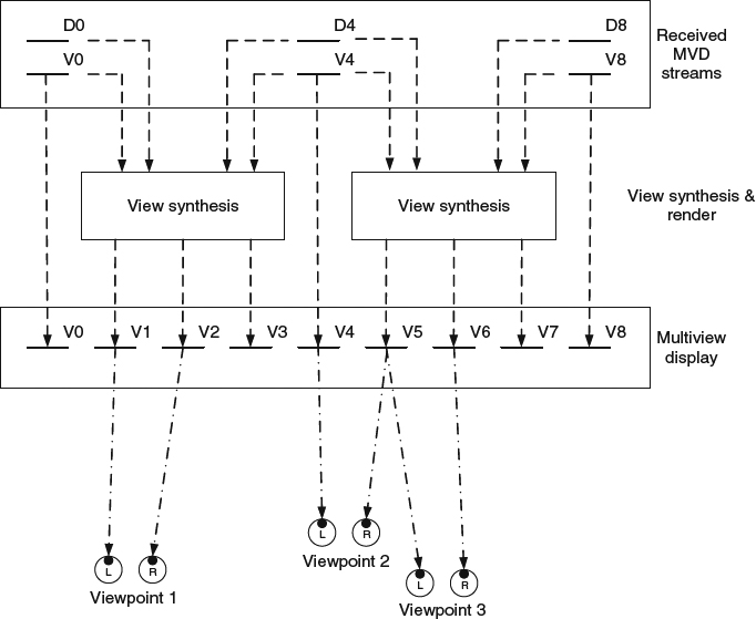
Figure 5.20 Decoding and rendering process in multi-view video plus depth video coding.
Note that instead of encoding N video-plus-depth streams individually, one feasible format of MVD for further bit rate reduction is to separate color sequences and depth sequences into two different multi-view sequence groups and encode each group with the H.264 MVC codec [50]. In other words, the MVD format can be delivered by two MVC streams. It has been reported that the PSNR for the luma component can show up to 0.5dB improvement, and the depth and chroma components can have up to 0.3dB performance gain. Since the color video sequence and the depth map show the same object in different representations, the object displacement and movement should be highly consistent in both groups of sequences. The motion vectors and selected coding mode used in the color video compressed bit stream and the depth map bit stream should have high correlation. Therefore, the mode decision and the motion vectors chosen in the color video sequence can be referenced during the depth map coding to reduce the encoder computation complexity. Moreover, it is proposed not to send the bits for motion vectors in the depth map bit stream to further reduce the bit rate. At the decoder, the decoding process of the depth map stream ignores the slack motion vectors stored in the depth map stream and performs motion compensation by taking motion vectors from the color video bit stream [51].
The success of MVD relies on the way the intermediate view is synthesized via view synthesis prediction (VSP). There have been several proposals to create a better synthesized view [52, 53]. The basic procedure for view synthesis consists of the following three steps: First, the view synthesis process will be invoked by projecting all the pixels in the two neighboring original views to the targeted virtual image planes. A collection process will follow to select the representative color information from each view. Finally, a fusion process is conducted to merge the color information from two nearby views.
If the cameras are calibrated with known parameters during the video capture stage, the projection can be conducted as follows. Denote the central camera as C1, the left side view camera as C0, and the right side view camera C2. Let Mi,0,, Mi,1, Mi,2 be the intrinsic matrices representing the intrinsic parameters, including the focal length, mapping between camera coordinate and image coordinate system, and geometric distortions, for left, central, and right cameras, respectively. Similarily, for each camera, let Me,0, Me,1, Me,2 be the extrinsic matrices representing the necessary geometric information to coordinate transform from the external coordinate system to the camera coordinate system. The extrinsic matrix, Me,k, has dimension 4 × 3 and consists of one 3 × 3 rotation matrix Re and one 3 × 1 translation matrix te (i.e., Me,k = [Re,k te,k]). Projection matrices M0, M1, M2, which are defined as multiplication of intrinsic matrix and extrinsic matrix (i.e., Mk = Mi,k Me,k), are used to project the 3D world points into the targeted image planes. To project a pixel in one original view to the new image plane, we first need to inverse project the pixel back to the world coordinate by taking the inverse projection matrix, Mk−1, and then project it onto the targeted plane using an interpolated projection matrix ![]() . As suggested in [54], the rotation matrix is interpolated via spherical linear interpolation to ensure the orthonormality of matrix, but the rest of parameters in the interpolated project matrix are linearly interpolated with weighting factor according to the distance to two neighboring cameras.
. As suggested in [54], the rotation matrix is interpolated via spherical linear interpolation to ensure the orthonormality of matrix, but the rest of parameters in the interpolated project matrix are linearly interpolated with weighting factor according to the distance to two neighboring cameras.
For each pixel with coordinate vk = [xk yk zk]T in its own camera coordinate for view k, we can have its corresponding position in the new virtual image plane as ![]() . Note that the projection won't create a one-to-one mapping to fill in both color and depth information for every pixel in the new image plane. Each pixel position may consist of n projected pixels, where n ≥ 0. A selection process is needed for depth and color information for the n > 0 case. The selection based on nearest estimated depth should be a good candidate since it represents the foreground object and may cover other backgrounds. Thus, a projected pixel with the nearest distance to the camera will be selected. The new depth information will be the new estimated depth, and the new color information will take the values from its corresponding pixel in the original view. At the end of this process, we will have two synthesized images for a targeted intermediate view: one is synthesized from the left-neighboring view and the other is synthesized from the right-neighboring view. The last stage is to linearly combine the two aforementioned synthesized images with a weighting factor according to the distance to the two neighboring cameras.
. Note that the projection won't create a one-to-one mapping to fill in both color and depth information for every pixel in the new image plane. Each pixel position may consist of n projected pixels, where n ≥ 0. A selection process is needed for depth and color information for the n > 0 case. The selection based on nearest estimated depth should be a good candidate since it represents the foreground object and may cover other backgrounds. Thus, a projected pixel with the nearest distance to the camera will be selected. The new depth information will be the new estimated depth, and the new color information will take the values from its corresponding pixel in the original view. At the end of this process, we will have two synthesized images for a targeted intermediate view: one is synthesized from the left-neighboring view and the other is synthesized from the right-neighboring view. The last stage is to linearly combine the two aforementioned synthesized images with a weighting factor according to the distance to the two neighboring cameras.
When the camera parameters are not available, one can resort to disparity estimation to calculate the disparity map between two neighboring views. The intermediate view will be synthesized by using the disparity information [55]. Similar to the video plus depth coding, the boundary artifact in the reconstructed depth map can be improved by the filtering process described in Section 5.4.