
8.6 Cross-Layer Design
As discussed in Chapter 6, network protocols are organized in what is a called a “layered architecture”. In this architecture, the different functions and services needed for end-to-end communication of information, 3D video in our case, are divided into stacked layers. At the transmitter side, upper layers of the stack pass on information to the layer immediately below and lower layers of the stack provide services to the layer immediately above. The key concept to note in the layered protocol stack architecture is that layers pass on information and provide services only to those contiguous layers immediately below and above a given layer. In a cross-layer approach, this concept is replaced by the idea that layers can exchange information and provide services between noncontiguous layers. This idea of cross-layering still maintains the modularity of layers seen in a layered architecture. Another interpretation for a cross-layer approach where modularity is lost, consists in merging multiple layers into a single one.
One application of cross-layer design for the wireless communication of 3D video is studied in [20]. In this case, cross-layering is proposed for the very interesting application, very much relevant to 3D video, where for the foreseeable future 3D video services will have to maintain backwards compatibility with 2D services. This is because during the period of mass-market deployment of 3D services and viewing devices, a good proportion of users will still be using devices that are only useful for 2D content. Consequently, a user with a 2D video viewing device should be able to see the limited content in 2D by extracting it from the backward-compatible 3D video stream. Within this setting, it is likely that the 2D video-transmitted information will be more important than the 3D one, for two reasons. The first reason is that initially a majority of users will still be using 2D devices and therefore the 2D video content would be more important because it would be reaching a larger audience. At the same time, the 2D video information could be considered as more important because it may be needed to recover the 3D video content (which is the case shown in Figure 8.11 when considering that frames types 0 and 1 form a 2D video sequence and the addition of frames of type 2 expand the video content to 3D). Also, 2D video may be considered more important because it can be seen as a lower quality service that a 3D receiver could switch to when some problem prevents the correct reception of video in 3D (this particular approach could also be studied in the context of the multiple description framework, as discussed in the previous section). Consequently, the work in [20] aims at designing a cross-layer scheme that assigns different physical layer resources to different parts of the encoded video. As such, the scheme in [20] allocates power and number of subcarriers for WiMAX transmission, differentiating between assignment for the more important color information (which applies also to 2D video) and for the less important video depth information (which is needed only for 3D video). One point of note in this work is that the presentation in [20] considers the design case of unequal error protections instead of one of cross-layer design. As presented in this chapter, unequal error protection refers to the allocation of different amount of FEC redundancy to different parts of the compressed 3D video stream, while the work in [20] is a case of cross-layer design.
Another design that uses a cross-layer technique linking the physical layer with the application layer to improve the quality of received 3D video transmitted over a wireless medium is the work in [21]. This is another case where the goal of the design is to efficiently allocate network resources by providing differentiated link quality for the more important color information and less important depth information appearing as two parts of the compressed video bit stream. The salient feature of the physical layer resource allocation is that in this case the problem is that of assigning different types of relay and relay signal processing operation to the color and video depth components of the bit stream to be transmitted. As shown in Figure 8.15, the transmission of information is not done through a direct transmission between source and destination, but instead through the use of a relay located between the source and destination.
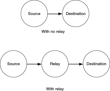
Figure 8.15 Communication with and without the use of a relay.
The operation of the relay in [21] follows the ideas within the paradigm of cooperative communications. Cooperative communications is a technique that is itself derived from studies on the relay channel [22] and presented in [23–25]. It is based on the broadcast nature of wireless channels where a transmitted signal can be overheard by other network nodes, called “relays”, and instead of traditionally treating the signal as interference and discarding it, it is processed at the relay, and retransmitted to the destination. The relays can be classified into different types depending on the processing done with the signal to be relayed. The two simplest and most popular types are amplify-and-forward (AF), where the relay simply amplifies the received signal and retransmits it, and decode-and-forward (DF), where the relay is capable of decoding the received signal, checking for errors, and if received correctly, re-encoding and retransmitting it.
Research on user cooperation has presented evidence that the use of these techniques is capable of improving the quality of the wireless link. At the same time, the use of a relay in the context of cooperative communications presents a tradeoff between received signal quality and transmit bit rate or other related metrics. This is because with the use of a relay it is necessary to allocate part of the resources that are usually used only for the transmission between the source and the destination – channel allocation, transmit bit rate, time slot duration, etc. – for the transmission from the relay to the destination. This is an important issue, especially when transmitting sources of information with the characteristics of 3D video. An analysis of this issue, for generic real-time multimedia sources can be found in [26]. The results here show that in a majority of cases, DF cooperation exhibits better performance than AF cooperation.
The work in [21] addresses the issues of allocating resources to the relay transmission and the difference in performance between AF and DF relaying. It does so by assigning the more important transmission of color information to the best of the group of relays that can perform DF operation, and by assigning the less important transmission of video depth information to the best of the group of relays that cannot perform DF operation and, thus, are available to operate using AF relaying. This operation is shown in Figure 8.16.
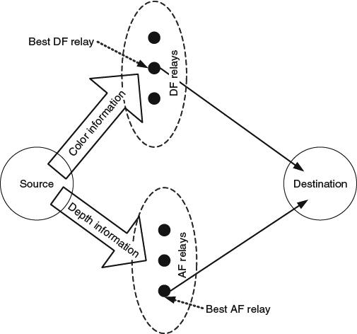
Figure 8.16 Transmission of 3D video information using two groups of relays.
The configuration of relays into two separate groups allows for the scheduling of transmissions, and the needed resources, as shown in Figure 8.17. As can be seen, the transmission of information is divided into phases. During the odd numbered phases the source is sending information and the best of the AF relays is sending video depth information to the destination. During the even numbered phases the source sends video depth information and the best of the DF relays sends the color information to the destination. Note that in practice, a DF relay cannot retransmit video depth information because doing so would require it to be receiving and transmitting at the same time, an operation that presents significant technical challenges due to the large difference between the powers of the two signals involved. For the same reason, an AF relay cannot transmit color information (an operation that would not be efficient anyway because the performance would not be as good as that achieved with a relay from the DF group). Also note that in order to allocate resources for the transmission of the relays, the time duration needed to transmit frames needs to be divided into two phases. Nevertheless, the separation of the relaying operation into the staggered transmission of two relays from two different groups does not require the use of any extra resources, and the only penalty is a small half-frame delay incurred during the transmission from the AF relay to the destination. Of course, the operation of the system is based on the assumption that the transmission from the source is not interfering with the reception at the destination.

Figure 8.17 Transmission schedule for source and relays.
The main difference between AF and DF operation is that for the latter it is necessary to successfully decode at the relay the transmitted information from the source. Then, the criteria used to allocate a relay to DF or AF is that the relays in the DF group are those with a channel from the source good enough that the decoding of the transmitted information is highly likely. Those relays for which the channel from the source is not as good are assigned to the AF group. This criterion also accounts for why DF relaying shows better performance. Once the groups of relays are set, it is necessary to choose the best relay within each group. This is done by choosing the relay within each group yielding the largest signal-to-noise ratio at the destination. This value depends on the quality of the channels between the source and the relay and between the relay and the destination.