
CHAPTER 41
Creating Particles and Particle Flow
Understanding the various particle systems
Creating a particle system
Using the Spray and Snow particle systems
Using the Super Spray and Blizzard particle systems
Working with MetaParticles
Using an object as an emitter
Using particle system maps
Using the Particle Flow interface
Every object that you add to the scene slows down Max to a small degree because Max needs to keep track of every object. If you add thousands of objects to a scene, not only does Max slow down noticeably, but also the objects become difficult to identify. For example, if you had to create thousands of simple snowflakes for a snowstorm scene, the system would become unwieldy, and the number wouldn't get very high before you ran out of memory.
Particle systems are specialized groups of objects that are managed as a single entity. By grouping all the particle objects into a single controllable system, you can easily make modifications to all the objects with a single parameter. This chapter discusses using these special systems to produce rain and snow effects, fireworks sparks, sparkling butterfly wings, and even fire-breathing dragons.
Understanding the Various Particle Systems
A particle is a small, simple object that is duplicated en masse, like snow, rain, or dust. Just as in real life, Max includes many different types of particles that can vary in size, shape, texture, color, and motion. These different particle types are included in various particle systems.
When a particle system is created, all you can see in the viewport is a single gizmo known as an emitter icon. An emitter icon is the object (typically a gizmo, but it can be a scene object) where the particles originate. Selecting a particle system gizmo makes the parameters for the particle system appear in the Modify panel.
Max includes the following particle systems:
- Particle Flow Source: Particles that can be defined using the Particle Flow window and controlled using actions and events.
- Spray: Simulates drops of water. These drops can be Drops, Dots, or Ticks. The particles travel in a straight line from the emitter's surface after they are created.
- Snow: Similar to the Spray system, with the addition of some fields to make the particles Tumble as they fall. You also can render the particles as Six Pointed shapes that look like snowflakes.
- Blizzard: An advanced version of the Snow system that can use the same mesh object types as the Super Spray system. Binding the system to the Wind Space Warp can create storms.
- PArray: Can use a separate distribution object as the source for the particles. For this system, you can set the particle type to Fragment and bind it to the PBomb Space Warp to create explosions.
- PCloud: Confines all generated particles to a certain volume. A good use of this system is to reproduce bubbles in a glass or cars on the road.
- Super Spray: An advanced version of the Spray system that can use different mesh objects, closely packed particles called MetaParticles, or an instanced object as its particles. Super Spray is useful for rain and fountains. Binding it to the Path Follow Space Warp can create waterfalls.
Creating a Particle System
You can find all the various particle systems under the Create panel and also in the Create menu. To access these systems, click the Geometry category and select the Particle Systems subcategory from the drop-down list. All the particle systems then appear as buttons. Or you can select the Create ![]() Particles menu.
Particles menu.
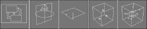
With the Particle Systems subcategory selected, click the button for the type of particle system that you want to use, and then click in a viewport to create the particle system emitter icon. The emitter icon is a gizmo that looks like a plane or a sphere and that defines the location in the system where the particles all originate. Attached to the icon is a single line that indicates the direction in which the particles move when generated. This line points by default toward the construction grid's negative Z-axis when first created. Figure 41.1 shows the emitter icons for each particle system type including, from left to right, Particle Flow Source; Super Spray; Spray, Snow, and Blizzard (which all have the same emitter icon); PArray; and PCloud.
FIGURE 41.1 The emitter icons for each particle system type
You can transform these icons using the standard transform buttons on the main toolbar. Rotating an emitter changes the direction in which the particles initially move.
After an icon is created, you can set the number, shape, and size of the particles and define their motion in the Parameter rollouts. To apply a material to the particles, simply apply the material to the system's icon. This material is applied to all particles included in the system.
Note
Be aware that the particles are displayed as simple objects such as ticks or dots in the viewports. To see the actual resulting particles, you need to render the scene file.
You can set the parameters for the Max particle systems in the Create panel when they are first created or in the Modify panel at any time. The simpler systems, Spray and Snow, have a single Parameters rollout, but the advanced systems—Particle Flow Source, Super Spray, and Blizzard—include multiple Parameters rollouts. The PArray and PCloud systems have similar multiple rollouts, with a few subtle differences, and the Particle Flow system includes several rollouts, but most of the action is with the Particle Flow window. The following sections describe how to use these rollouts to set the parameters for the various particle systems.
Using the Spray and Snow Particle Systems
All I can say about the Spray and Snow particle systems is that when it rains, it pours. The Spray Parameters rollout includes values for the number of particles to be included in the system. These values can be different for the viewport and the renderer. By limiting the number of particles displayed in the viewport, you can make the viewport updates quicker. You also can specify the drop size, initial speed, and variation. The Variation value alters the spread of the particles’ initial speed and direction. A Variation value of 0 makes the particles travel in a straight line away from the emitter.
Spray particles can be Drops, Dots, or Ticks, which affect how the particles look only in the viewport. Drops appear as streaks, Dots are simple points, and Ticks are small plus signs. You also can set how the particles are rendered—as Tetrahedron objects or as Facing objects (square faces that always face the viewer).
Note
The Facing option is visible only in the Perspective view but can be rendered using any viewport, including a camera viewport.
The Timing values determine when the particles appear and how long the particles stay around. The Start Frame is the first frame where particles begin to appear, and the Life value determines the number of frames in which the particles are visible. When a particle's lifetime is up, it disappears. The Birth Rate value lets you set how many new particles appear in each frame; you can use this setting or select the Constant option. The Constant option determines the Birth Rate value by dividing the total number of particles by the number of frames.
The emitter dimensions specify the width and height of the emitter gizmo. You also can hide the emitter with the Hide option.
Note
The Hide option hides the emitter only in the viewports. Emitters are never rendered.
The parameters for the Snow particle system are similar to the Spray particle system, except for a few unique settings. Snow can be set with a Tumble and Tumble Rate. The Tumble value can range from 0 to 1, with 1 causing a maximum amount of rotation. The Tumble Rate determines the speed of the rotation.
The Render options are also different for the Snow particle system. The three options are Six Point, Triangle, and Facing. The Six Point option renders the particle as a six-pointed star. Triangles and Facing objects are single faces.
Tutorial: Creating rain showers
One of the simplest uses for particle systems is to simulate rain or snow. In this tutorial, you use the Spray system to create rain and then learn how to use the Snow system to create snow.
To create a scene with rain using the Spray particle system, follow these steps:
- Open the Simple rain.max file from the Chap 41 directory on the CD.
This file includes an umbrella model created by Zygote Media.
- Select the Create
 Particles Spray menu command, and drag the icon in the Top viewport to cover the entire scene. Position the icon above the objects, and make sure that the vector is pointing down toward the scene objects.
 - Open the Modify panel, and in the Parameters rollout, set the Render Count to 1000 and the Drop Size to 2. Keep the default speed of 10, and select the Drops option; these settings make the particles appear as streaks. Select the Tetrahedron Render method, and set the Start and Life values to 0 and 100, respectively.
Note
To cover the entire scene with an average downpour, set the number of particles to 1000 for a 100-frame animation.
- Open the Material Editor (by pressing the M key), and drag a light blue–colored material to the particle system icon.
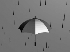
Figure 41.2 shows the results of this tutorial.
FIGURE 41.2 Rain created with the Spray particle system
Tutorial: Creating a snowstorm
Creating a snowstorm is very similar to what you did in the preceding tutorial. To create a snowstorm, use the Snow particle system with the same number of particles and apply a white material to the particle system.
To create a scene with snow using the Snow particle system, follow these steps:
- Open the Snowman in snowstorm.max file from the Chap 41 directory on the CD.
This file includes a snowman created using primitive objects.
- Select the Create Particles Snow menu command, and drag the icon in the Top viewport to cover the entire scene. Position the icon above the objects, and make sure that the vector is pointing down toward the scene objects.
- Open the Modify panel, and in the Parameters rollout, set the Render Count to 1000 and the Flake Size to 6, and use the Six Point Render option. Set the Start and Life values to 0 and 100, respectively.
- Open the Material Editor (by pressing the M key), and drag a white-colored material with some self-illumination added to the particle system gizmo.
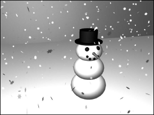
Figure 41.3 shows the results of this tutorial.
FIGURE 41.3 A simple snowstorm created with the Snow particle system
Using the Super Spray Particle System
If you think of the Spray particle system as a light summer rain shower, then the Super Spray particle system is like a fire hose. The Super Spray particle system is considerably more complex than its Spray and Snow counterparts. With this complexity comes a host of features that make this one of the most robust effects creation tools in Max.
Unlike the Spray and Snow particle systems, the Super Spray particle system includes several rollouts.
Super Spray Basic Parameters rollout
The Super Spray particle system emits all particles from the center of the emitter icon. The emitter icon is a simple cylinder and an arrow that points in the direction in which the particles will travel. In the Basic Parameters rollout, shown in Figure 41.4, the Off Axis value sets how far away from the icon's arrow the stream of particles will travel. A value of 0 lines up the particle stream with the icon's arrow, and a value of 180 emits particles in the opposite direction. The Spread value can range from 0 to 180 degrees and fans the particles equally about the specified axis. The Off Plane value spins the particles about its center axis, and the Spread value sets the distance from this center axis that particles can be created. If all these values are left at 0, then the particle system emits a single, straight stream of particles, and if all values are 180, then particles go in all directions from the center of the emitter icon.
FIGURE 41.4 The Basic Parameters rollout lets you specify where and how the particles appear in the viewports.
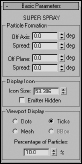
The icon size can be set or the icon can be hidden in the viewport. You also can set the particles to be displayed in the viewport as Dots, Ticks, Meshes, or Bounding Boxes. The Percentage value is the number of the total particles that are visible in the viewport and should be kept low to ensure rapid viewport updates.
Particle Generation rollout
The Particle Generation rollout, shown in Figure 41.5, is where you set the number of particles to include in a system as either a Rate or Total value. The Rate value is the number of particles per frame that are generated. The Total value is the number of particles generated over the total number of frames. Use the Rate value if you want the animation to have a steady stream of particles throughout the animation; use the Total value if you want to set the total number of particles that will appear throughout the entire range of frames.
FIGURE 41.5 The Particle Generation rollout lets you control the particle motion.
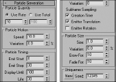
In the Particle Motion group, the Speed value determines the initial speed and direction of particles. The Variation value alters this initial speed as a percentage of the Speed value. A high Variation value results in particles with all sorts of different speeds.
Note
Be sure to use the Variation values liberally to get more realistic particle behavior.
In the Particle Timing group, you can set when the emitting process starts and stops. Using the Display Until value, you also can cause the particles to continue displaying after the emitting has stopped. The Life value is how long particles stay around, which can vary based on another Variation setting.
When an emitter is animated (such as moving back and forth), the particles can clump together where the system changes direction. This clumping effect is called puffing. The Subframe Sampling options help reduce this effect. The three options are Creation Time (which controls emitting particles over time), Emitter Translation (which controls emitting particles as the emitter is moved), and Emitter Rotation (which controls emitting particles as the emitter is rotated). All three options can be enabled, but each one that is enabled adds the computation time required to the render.
Note
The Subframe Sampling options increase the rendering time and should be used only if necessary.
You can specify the particle size along with a Variation value. You also can cause the particles to grow and fade for a certain number of frames.
The Seed value helps determine the randomness of the particles. Clicking the New button automatically generates a new Seed value.
Note
If you clone a particle system and each system has the same Seed value, then the two systems will be exactly the same. Two cloned particle systems with different Seed values will be unique.
Particle Type rollout
The Particle Type rollout, shown in Figure 41.6, lets you define the look of the particles. At the top of the rollout are three Particle Type options: Standard Particles, MetaParticles, and Instanced Geometry.
FIGURE 41.6 The Particle Type rollout (shown in four parts) lets you define how the particles look.
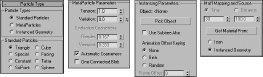
If you select Standard Particles as the particle type, you can select which geometric shape you want to use from the Standard Particles section. The options are Triangle, Special, Constant, SixPoint, Cube, Facing, Tetra, and Sphere.
The Special type consists of three intersecting planes, which are useful if you apply maps to them. The Facing type is also useful with maps; it creates a simple square face that always faces the viewer. The Constant type maintains the same pixel size, regardless of the distance from the camera or viewer. The Six Point option renders each particle as a 2D six-pointed star. All other types are common geometric objects.
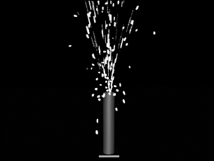
Tutorial: Creating a fireworks fountain
For an example of the Super Spray particle system, you create a fireworks fountain. Fireworks are essentially just lots of particles with a short life span and a high amount of self-illumination. (Tell yourself that the next time you watch a fireworks display.)
Cross-Reference
The ready-made material for this example uses the Glow Render effect to make the particles glow. You can learn more about render effects in Chapter 46, “Using Atmospheric and Render Effects.”
To create a fireworks fountain using a particle system, follow these steps:
- Open the Fireworks fountain.max file from the Chap 41 directory on the CD.
This file includes a simple fountain base and the Gravity space warp to cause the particles to curve back toward the ground.
Tip
Some of the most amazing special effects are made possible by combining particle systems with Space Warps.
- Select the Create Particles Super Spray menu command, drag in the Top view, and position the system at the top of the cylinder with the direction arrow pointing toward the sky.
- Open the Modify panel, and set the Off Axis Spread to 45 and the Off Plane Spread to 90. In the Particle Generation rollout, set the Total of particles to 2000 with a Speed of 20 and a Variation of 100. Set the Emit Start to 0 and the Emit Stop to 100. Set the Display Until to 100 and the Life to 25 with a Variation of 20. The Size of the particles should be 5.
- Open the Material Editor (by pressing the M key), and select the first sample slot. This slot includes a material named Spark. Drag the material from the Material Editor to the particle system's icon.
- Select the Super Spray icon, right-click it to open the pop-up menu, and select the Properties menu option. In the Object Properties dialog box, select the Object Motion Blur option.
Caution
When viewing the animation, maximize a single viewport. If Max tries to update all four viewports at once with this many particle objects, the update is slow. The shortcut to maximize the viewport is Alt+W.
Figure 41.7 shows sparks emitting from the fireworks fountain.
FIGURE 41.7 The Super Spray particle system is used to create fireworks sparks.
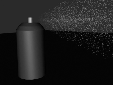
Tutorial: Adding spray to a spray can
The Super Spray particle system is complex enough to warrant another example. What good is a spray can without any spray? In this tutorial, you create a spray can model and then use the Super Spray particle system to create the spray coming from it.
To create a stream of spray for a spray can, follow these steps:
- Open the Spray can.max file from the Chap 41 directory on the CD.
This file includes a simple spray can object created using a cylinder for the can base and the nozzle and a lathed spline for the top of the can.
- Select the Particle Systems subcategory button from the drop-down list, and click the Super Spray button. Drag in the Top viewport to create the Super Spray icon, and position it at the mouth of the nozzle.
- In the Basic Parameters rollout, set the Off Axis Spread to 20 and the Off Plane Spread to 90. In the Particle Generation rollout, set the Emit Rate to 1000, the Speed to 20, and the Life to 30. Set the Size of the particles to 5.
- Open the Material Editor (by pressing M), and select the material named Spray Mist. Then drag this material onto the Super Spray icon to apply this material to the Super Spray particle system.
Figure 41.8 shows the fine spray from an aerosol can.
FIGURE 41.8 Using a mostly transparent material, you can create a fine mist spray.
Using the MetaParticles option
The MetaParticles option in the Particle Type rollout makes the particle system release Metaball objects. Metaballs are viscous spheres that, like mercury, flow into each other when close. These particles take a little longer to render but are effective for simulating water and liquids. The MetaParticles type is available for the Super Spray, Blizzard, PArray, and PCloud particle systems.
Selecting the MetaParticles option in the Particle Types section enables the MetaParticle Parameters group. In this group are options for controlling how the MetaParticles behave. The Tension value determines how easily objects blend together. MetaParticles with a high tension resist merging with other particles. You can vary the amount of tension with the Variation value. The Tension value can range between 0.1 and 10, and the Variation can range from 0 to 100 percent.
Because MetaParticles can take a long time to render, the Evaluation Coarseness settings enable you to set how computationally intensive the rendering process is. This can be set differently for the viewport and the renderer—the higher the value, the quicker the results. You also can set this to Automatic Coarseness, which automatically controls the coarseness settings based on the speed and ability of the renderer. The One Connected Blob option speeds the rendering process by ignoring all particles that aren't connected.
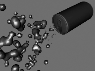
Tutorial: Spilling soda from a can
MetaParticles are a good option to use to create drops of liquid, like those from a soda can.
To create liquid flowing from a can, follow these steps:
- Open the MetaParticles from a soda can.max file from the Chap 41 directory on the CD.
This file includes a soda can model created by Zygote Media positioned so the can is on its side.
- Select the Create Particles Super Spray menu command, and drag the icon in the Front viewport. Position the icon so that its origin is at the opening of the can and the directional vector is pointing outward.
- With the Super Spray icon selected, open the Modify panel, and in the Basic Parameters rollout, set the Off Axis and Off Plane Spread values to 40.
- In the Particle Generation rollout, keep the default Rate and Speed values, but set the Speed Variation to 50 to alter the speed of the various particles. Set the Particle Size to 20.
- In the Particle Type rollout, select the MetaParticles option, set the Tension value to 1, and make sure that the Automatic Coarseness option is selected.
- Open the Material Editor (by pressing the M key), and drag the Purple Soda material to the particle system icon.
Figure 41.9 shows a rendered image of the MetaParticles spilling from a soda can at frame 25.
FIGURE 41.9 MetaParticles emitting from the opening of a soda can
Instanced Geometry
Using the Particle Type rollout, you can select an object to use as the particle. If the Instanced Geometry option is selected as the particle type, you can select an object to use as the particle. To choose an object to use as a particle, click the Pick Object button and then select an object from the viewport. If the Use Subtree Also option is selected, then all child objects are also included.
Caution
Using complicated objects as particles can slow down a system and increase the rendering time.
The Animation Offset Keying option determines how an animated object that is selected as the particle is animated. The None option animates all objects the same, regardless of when they are born. The Birth option starts the animation for each object when it is created, and the Random option offsets the timing randomly based on the Frame Offset value. For example, if you have selected an animated bee that flaps its wings as the particle, and you select None as the Animation Offset Keying option, all the bees flap their wings in concert. Selecting the Birth option instead starts them flapping their wings when they are born, and selecting Random offsets each instance differently.
For materials, the Time and Distance values determine the number of frames or the distance traveled before a particle is completely mapped. You can apply materials to the icon that appears when the particle system is created. The Get Material From button lets you select the object from which to get the material. The options include the icon and the Instanced Geometry.
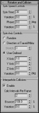
Rotation and Collision rollout
In the Rotation and Collision rollout is an option to enable interparticle collisions. This option causes objects to bounce away from one another when their object boundaries overlap.
The Rotation and Collision rollout, shown in Figure 41.10, contains several controls to alter the rotation of individual particles. The Spin Time is the number of frames required to rotate a full revolution. The Phase value is the initial rotation of the particle. You can vary both of these values with Variation values.
Note
The Rotation and Collision rollout options also can increase the rendering time of a scene.
You also can set the axis about which the particles rotate. Options include Random, Direction of Travel/MBlur, and User Defined. The Stretch value under the Direction of Travel option causes the object to elongate in the direction of travel. The User Defined option lets you specify the degrees of rotation about each axis.
Interparticle collisions are computationally intensive and can easily be enabled or disabled with the Enable option. You also can set how often the collisions are calculated. The Bounce value determines the speed of particles after collisions as a percentage of their collision speed. You can vary the amount of Bounce with the Variation value.
FIGURE 41.10 The Rotation and Collision rollout options can control how objects collide with one another.
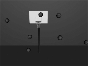
Tutorial: Basketball shooting practice
When an entire team is warming up before a basketball game, the space around the basketball hoop is quite chaotic—with basketballs flying in all directions. In this tutorial, you use a basketball object as a particle and spread it around a hoop. (Watch out for flying basketballs!)
To use a basketball object as a particle, follow these steps:
- Open the Basketballs at a hoop.max file from the Chap 41 directory on the CD.
This file includes basketball and basketball hoop models created by Zygote Media.
- Select the Create Particles Super Spray menu command, and drag the icon in the viewport. Position the icon in the Front view so that its origin is above and slightly in front of the hoop and the directional vector is pointing down. (You need to rotate the emitter icon.)
- Open the Modify panel, and in the Basic Parameters rollout, set the Off Axis Spread value to 90 and the Off Plane Spread value to 40; this randomly spreads the basketballs around the hoop. In the Viewport Display group of the Basic Parameters rollout, select the Mesh option. Set the Percentage of Particles to 100 percent to see the position of each basketball object in the viewport.
Caution
Because the basketball is a fairly complex model, using the Mesh option severely slows down the viewport update. You can speed the viewport display using the Bbox (Bounding Box) option, but you'll need to choose it after selecting the Instanced Geometry option.
- In the Particle Generation rollout, select the Use Total option, and enter 30 for the value. (This number is reasonable and not uncommon during warm-ups.) Set the Speed value to 0.2 and the Life value to 100 because you don't want basketballs to disappear. Because of the low number of particles, you can disable the Subframe Sampling options. Set the Grow For and Fade For values to 0.
- In the Particle Type rollout, select the Instanced Geometry option and click the Pick Object button. Make sure that the Use Subtree Also option is selected to get the entire group, and then select the basketball group in the viewport. At the bottom of this rollout, select the Instanced Geometry option and click the Get Material From button to give all the particles the same material as the original object.
- In the Rotation and Collision rollout, set the Spin Time to 100 to make the basketballs spin as they move about the scene. Set the Spin Axis Control to Random. Also enable the Interparticle Collisions option, and set the Calculation Interval to 1 and the Bounce value to 100.
With the Collisions option enabled, the basketballs are prevented from overlapping one another.
- At the floor of the basketball hoop is a Deflector Space Warp. Click the Bind to Space Warp button on the main toolbar, and drag from this floor deflector to the Super Spray icon.
This makes the basketballs bounce off the floor.
Figure 41.11 shows a rendered image of the scene at frame 30 with several basketballs bouncing chaotically around a hoop.
FIGURE 41.11 Multiple basketball particles flying around a hoop
Object Motion Inheritance rollout
The settings on the Object Motion Inheritance rollout, shown in Figure 41.12, determine how the particles move when the emitter is moving. The Influence value defines how closely the particles follow the emitter's motion; a value of 100 has particles follow exactly, and a value of 0 means they don't follow at all.
FIGURE 41.12 The Object Motion Inheritance rollout sets how the particles inherit the motion of their emitter, and the Bubble Motion rollout defines how particles act like bubbles.
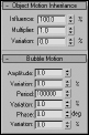
The Multiplier value can exaggerate or diminish the effect of the emitter's motion. Particles with a high multiplier can actually precede the emitter.
Bubble Motion rollout
The Bubble Motion rollout, also shown in Figure 41.12, simulates the wobbling motion of bubbles as they rise in a liquid. Three values define this motion, each with variation values. Amplitude is the distance that the particle moves from side to side. Period is the time that it takes to complete one side-to-side motion cycle. Phase defines where the particle starts along the amplitude curve.
Particle Spawn rollout
The Particle Spawn rollout, shown in Figure 41.13, sets options for spawning new particles when a particle dies or collides with another particle. If the setting is None, colliding particles bounce off one another and dying particles simply disappear. The Die After Collision option causes a particle to disappear after it collides. The Persist value sets how long the particle stays around before disappearing. The Variation value causes the Persist value to vary by a defined percentage.
FIGURE 41.13 The Particle Spawn rollout (shown in two parts) can cause particles to spawn new particles.
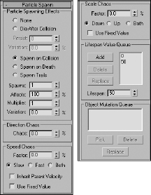
The Spawn on Collision, Spawn on Death, and Spawn Trails options all enable the spawn controls and define when particles spawn new particles. The Spawns value is the number of times a particle can spawn other particles. The Affects value is the percentage of particles that can spawn new particles; lowering this value creates some duds that do not spawn. The Multiplier value determines the number of new particles created.
Note
The Spawn Trails option causes every particle to spawn a new particle at every frame. This option can quickly create an enormous number of particles and should be used with caution.
The Chaos settings define the direction and speed of the spawned particles. A Direction Chaos value of 100 gives the spawned particles the freedom to travel in any direction, whereas a setting of 0 moves them in the same direction as their originator.
The Chaos Speed Factor is the difference in speed between the spawned particle and its originator. This factor can be faster or slower than the original. Selecting the Both option speeds up some particles and slows others randomly. You also can choose to have spawned particles use their parent's velocity or use the factor value as a fixed value.
The Scale Chaos Factor works similarly to the Chaos Speed Factor, except that it scales particles to be larger or smaller than their originator.
The Lifespan Value Queue lets you define different lifespan levels. Original particles have a lifespan equal to the first entry in the queue. The particles that are spawned from those spawned particles last as long as the second value, and so on. To add a value to the list, enter the value in the Lifespan spinner and click the Add button. The Delete button removes values from the list, and the Replace button switches value positions.
If Instanced Geometry is the selected particle type, you can fill the Object Mutation Queue with additional objects to use at each spawn level. These objects appear after a particle is spawned. To pick a new object to add to the queue, use the Pick button. You can select several objects, and they are used in the order in which they are listed.
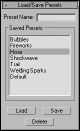
Load/Save Presets rollout
You can save and load each particle configuration using the Load/Save Presets rollout, shown in Figure 41.14. To save a configuration, type a name in the Preset Name field and click the Save button. All saved presets are displayed in the list. To use one of these preset configurations, select it and click the Load button.
FIGURE 41.14 The Load/Save Presets rollout enables you to save different parameter settings.
Note
A saved preset is valid only for the type of particle system used to save it. For example, you cannot save a Super Spray preset and load it for a Blizzard system.
Max includes several default presets that can be used as you get started. These presets include Bubbles, Fireworks, Hose, Shockwave, Trail, Welding Sparks, and Default (which produces a straight line of particles).
Using the Blizzard Particle System
The Blizzard particle system uses the same rollouts as the Super Spray system, with some slightly different options. The Blizzard emitter icon is a plane with a line pointing in the direction of the particles (similar to the Spray and Snow particle systems). Particles are emitted across the entire plane surface.
The differences between the Blizzard and Super Spray parameters include dimensions for the Blizzard icon. In the Particle Generation rollout, you'll find values for Tumble and Tumble Rate. Another difference is the Emitter Fit Planar option under the Material Mapping group of the Particle Type rollout. This option sets particles to be mapped at birth, depending on where they appear on the emitter. The other big difference is that the Blizzard particle system has no Bubble Motion rollout, because snowflakes don't make very good bubbles. Finally, you'll find a different set of presets in the Load/Save Presets rollout, including Blizzard, Rain, Mist, and Snowfall.
Using the PArray Particle System
The PArray particle system is a unique particle system. It emits particles from the surface of a selected object. These particles can be emitted from the object's surface, edges, or vertices. The particles are emitted from an object separate from the emitter icon.
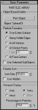
The PArray particle system includes many of the same rollouts as the Super Spray particle system. The PArray particle system's emitter icon is a cube with three tetrahedron objects inside it. This system has some interesting parameter differences, starting with the Basic Parameters rollout, shown in Figure 41.15.
FIGURE 41.15 The Basic Parameters rollout for the PArray particle system lets you select the location where the particles form.
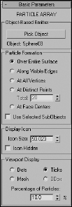
In the PArray system, you can select separate objects as emitters with the Pick Object button. You also can select the location on the object where the particles are formed. Options include Over Entire Surface, Along Visible Edges, At All Vertices, At Distinct Points, and At Face Centers. For the At Distinct Points option, you can select the number of points to use.
The Use Selected SubObject option forms particles in the locations selected with the Pick Object button, but only within the subobject selection passed up the Stack. This is useful if you want to emit particles only from a certain selection of a mesh, such as a dragon's mouth or the end of a fire hose. The other options in the PArray system's Basic Parameters rollout are the same as in the other systems.
The Particle Generation rollout includes a Divergence value. This value is the angular variation of the velocity of each particle from the emitter's normal.
Splitting an object into fragments
The Particle Type rollout for the PArray system contains a unique particle type: Object Fragments. This type breaks the selected object into several fragments. Object Fragment settings include a Thickness value. This value gives each fragment a depth. If the value is set to 0, the fragments are all single-sided polygons.
Also in the Particle Type rollout, the All Faces option separates each individual triangular face into a separate fragment. An alternative to this option is to use the Number of Chunks option, which enables you to divide the object into chunks and define how many chunks to use. A third option splits up an object based on the smoothing angle, which can be specified.
In the Material section of the Particle Type rollout, you can select material IDs to use for the fragment's inside, outside, and backside.
The Load/Save Presets rollout includes a host of interesting presets, including the likes of Blast, Disintegrate, Geyser, and Comet.
Tutorial: Creating rising steam
In this tutorial, you create the effect of steam rising from a street vent. Using the PArray particle system, you can control the precise location of the steam.
To create the effect of steam rising from a vent, follow these steps:
- Open the Street vent.max file from the Chap 41 directory on the CD.
This file includes a street scene with a vent. The car model was created by Viewpoint Datalabs.
- Select the Create Particles PArray menu command, and drag in the Front viewport to create the system.
- In the Basic Parameters rollout, click the Pick Object button and select the Quadpatch object that is positioned directly beneath the vent object. Set the Particle Formation option to Over Entire Surface.
Because the Plane object only has a single face, the particles travel in the direction of the Plane's normal.
- In the Particle Generation rollout, set the Emit Stop value to 100 and the Life value to 60 with a Variation of 50. Set the Particle Size value to 5.0 with a Variation of 30.
- In the Particle Type rollout, select the Standard Particles and the Constant options.
- Open the Material Editor (by selecting the M key), and name the selected sample slot steam. Click the map button to the right of the Opacity value, and double-click the Mask map type from the Material/Map Browser. In the Mask Parameters rollout, click the map button and select the Noise map type. Then click the Go to Parent button to return to the Mask map, click the Mask button, and select the Gradient map type. For the Gradient material, drag the black color swatch to the white color swatch, select Swap in the dialog box that appears, and enable the Radial option. Finally, drag the steam material to the PArray icon.
Figure 41.16 shows the steam vent at frame 60.
FIGURE 41.16 A Plane object positioned beneath the vent is an emitter for the particle system.
Using the PCloud Particle System
The PCloud particle system keeps all emitted particles within a selected volume. This volume can be a box, sphere, cylinder, or a selected object. The emitter icon is shaped as the selected volume. This particle system includes the same rollouts as the Super Spray system, with some subtle differences.
The options on the Basic Parameters rollout are unique to this system. This system can use a separate mesh object as an emitter. To select this emitter object, click the Pick Object button and select the object to use. Other options include Box, Sphere, and Cylinder Emitter. For these emitters, the Rad/Len, Width, and Height values are active for defining its dimensions.
In addition to these differences in the Basic Parameters rollout, several Particle Motion options in the Particle Generation rollout are different for the PCloud system as well. Particle Motion can be set to a random direction, a specified vector, or in the direction of a reference object's Z-axis.
The only two presets for this particle system in the Load/Save Presets rollout are Cloud/Smoke and Default.
Using Particle System Maps
Using material maps on particles is another way to add detail to a particle system without increasing its geometric complexity. You can apply all materials and maps available in the Material Editor to particle systems. To apply them, select the particle system icon and click the Assign Material to Selection button in the Material Editor.
For more details on using maps, see Chapter 17, “Adding Material Details with Maps.”
Two map types are specifically designed to work with particle systems: Particle Age and Particle MBlur. You can find these maps in the Material/Map Browser. You can access the Material/Map Browser using the Rendering ![]() Material Map Browser menu command or from the Material Editor by clicking the Get Material button.
Material Map Browser menu command or from the Material Editor by clicking the Get Material button.
Using the Particle Age map
The Particle Age map parameters include three different colors that can be applied at different times, depending on the Life value of the particles. Each color includes a color swatch, a map button, an Enable check box, and an Age value for when this color should appear.
This map typically is applied as a Diffuse map because it affects the color.
Using the Particle MBlur map
The Particle MBlur map changes the opacity of the front and back of a particle, depending on the color values and sharpness specified in its parameters rollout. This results in an effect of blurred motion if applied as an Opacity map.
Note
MBlur does not work with the Constant, Facing, MetaParticles, or PArray object fragments.
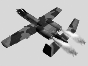
Tutorial: Creating jet engine flames
The Particle Age and MBlur maps work well for adding opacity and colors that change over time, such as hot jets of flames, to a particle system.
To create jet engine flames, follow these steps:
- Open the Jet airplane flames.max file from the Chap 41 directory on the CD.
This file includes an A-10 airplane model created by Viewpoint Datalabs.
- Select the Create Particles Super Spray menu command, and drag the icon in the viewport. Rotate and position the emitter icon so that its origin is right in the jet's exhaust port and the directional vector is pointing outward, away from the jet.
- Open the Modify panel, and in the Basic Parameters rollout, set the Off Axis Spread value to 20 and the Off Plane Spread value to 90.
These settings focus the flames shooting from the jet's exhaust.
- In the Particle Generation rollout, set the Emit Stop to 100, the Life value to 30, and the Particle Size to 5.0.
- In the Particle Type rollout, select the Standard Particles option and select the Sphere type.
- Open the Material Editor by pressing the M key, and select the first sample slot. Name this material Jet's Exhaust, and click the map button to the right of the Diffuse color.
- From the Material/Map Browser that opens, select the Particle Age map. In the Particle Age Parameters rollout, select dark red, dark yellow, and black as colors for the ages 0, 50, and 100.
You should use darker colors because the scene is lighted.
- Click the Go to Parent button to access the Jet's Exhaust material again, and then click the map button to the right of the Opacity setting. Select the Particle MBlur map.
- In the Particle MBlur Parameters rollout, make Color #1 white and Color #2 black with a Sharpness value of 0.1. Then drag this material from its sample slot onto the particle system's icon to apply the material (or click the Assign Material to Selection button if the emitter icon is still selected).
- With the Shift key held down, drag the Super Spray icon in the Front viewport to the other exhaust port. Make the new Super Spray an instance of the original.
Figure 41.17 shows the jet at frame 30 with its fiery exhaust.
FIGURE 41.17 Realistic jet flames created using the Particle Age and MBlur maps
Controlling Particles with Particle Flow
Particle systems like Super Spray are great for certain applications, but they suffer from an inflexibility. Each system has lots of parameters, but once the parameters are set, the particles follow the set parameters without changing. The Particle Flow system is an event-driven system that constantly tests its particles for certain criteria and alters its actions based on these defined criteria. This gives you the ability to program the particles to react in unique and different ways not possible with the other systems.
The Particle Flow Source option in the Create ![]() Particles menu is more than just a new particle system: It is a whole new interface and paradigm that you can use to control particles throughout their life. This is accomplished using the Particle View window, where you can visually program the flow of particles.
Particles menu is more than just a new particle system: It is a whole new interface and paradigm that you can use to control particles throughout their life. This is accomplished using the Particle View window, where you can visually program the flow of particles.
The Particle View window
The Particle View window, shown in Figure 41.18, is opened by clicking the Particle View button in the Setup rollout when a Particle Flow Source icon is selected or by pressing the keyboard shortcut, 6. Pressing 6 opens the Particle View window even if its icon isn't selected.
FIGURE 41.18 The Particle View window lets you program the flow of particles using a visual editor.
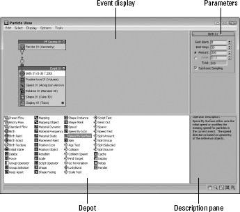
The Particle View window is divided into four panes. The Event display contains all the event nodes. These nodes contain individual actions, and nodes can be wired to one another to define the flow. The Parameter pane in the upper-right corner displays the parameters in rollouts for the action selected in the Event display. The Depot pane is below the Event display pane and contains all the possible actions that can work with particles. In the lower right is a Description pane that offers a brief description of the action that is selected in the Depot pane. Except for the Event display pane, you can turn off the other panes using the Display menu.
In the lower-right corner of the window are several display tools. These tools can be used to navigate the Event display. The Display tools include Pan, Zoom, Region Zoom, Zoom Extents, and No Zoom. The No Zoom button eliminates all zooming and displays the nodes at their normal size.
With the Particle View window open, you can Pan the Event display by dragging the scroll wheel on the mouse.
The Standard Flow
When the Particle Flow (PF) Source icon is created and the Particle View window is first opened, two nodes appear in the Event display. These nodes are called a Standard Flow. These two nodes identify the Particle Flow Source and are wired to an event node containing a Birth action. The Birth action defines when particles Start and Stop and the Amount or Rate. You can change these values by selecting the Birth event in the Event display and changing its parameters in the rollout that appears in the Parameters pane.
Several other default events appear in this default event node, including Position Icon, Speed, Rotation, Shape, and Display. Each of these events has parameters that you can alter that appear in the Parameters pane when the action is selected, and each event and action is identified with a number (such as 01) that appears next to its name. Each new event or action gets an incremented number. You also can rename any of these events if you right-click the event and select Rename from the pop-up menu.
A new Standard Flow can be created using the Edit ![]() New
New ![]() Particle System
Particle System ![]() Standard Flow menu command. An Empty Flow includes only the PF Source node. When a new Standard Flow (or Empty Flow) is created in the Particle Flow window, a PF Source icon is added to the viewports. And if the PF Source icon is deleted in the viewports, the associated event nodes are also deleted in the Particle Flow window.
Standard Flow menu command. An Empty Flow includes only the PF Source node. When a new Standard Flow (or Empty Flow) is created in the Particle Flow window, a PF Source icon is added to the viewports. And if the PF Source icon is deleted in the viewports, the associated event nodes are also deleted in the Particle Flow window.
Working with actions
The Depot pane includes all the different actions that can affect particles. These actions can be categorized into Birth actions (identified with green icons), Operator actions (identified with blue icons), Test actions (identified with yellow icons), and Miscellaneous actions (which are also blue). Each of these categories also can be found in the Edit ![]() New menu.
New menu.
New events can be dragged from the Depot pane to the Event display. If you place them within an existing node, a blue line appears at the location where the action will appear when dropped. The particles are affected within a node in the order, from top to bottom, in which they appear. If a new action from the Depot is dragged over the top of an existing action in the Event display, a red line appears on top of the existing action. When you drop the new action, it replaces the existing action.
Actions also can be dropped away from an event node, making it a new event node. If an event is a new node, then you can wire certain actions that are tested as true. For example, if you have a set of particles with a random speed assigned, then you could use a Test event to determine which particles are moving faster than a certain speed and wire those particles to change size using the new event node.
Clicking the action's icon disables the action.
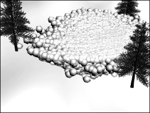
Tutorial: Creating an avalanche
One of the cautions that come with particles is that if you're not careful, you can quickly spawn enough particles to bring any system to its knees. Using the particle spawn feature is one of the worst offenders. For this tutorial, you use a Collision Spawn action to create an avalanche, but you must be sure to keep the number of spawned particles in check.
To use Particle Flow to make an avalanche effect, follow these steps:
- Open the Avalanche.max file from the Chap 41 directory on the CD.
This file includes a simple hillside covered with snow.
- Select Create Space Warps Deflectors SOmniFlect, and drag in the Top viewport to create a spherical deflector that covers the entire hill. Click the Select and Scale tool, and in the Z-axis, scale the SOmniFlect sphere down in the Left viewport until it is roughly the same thickness as the hill object. Then rotate the SOmniFlect until it is aligned parallel to the hill. This deflector is going to keep the snowball particles on top of the hill.
- Select Create Particles Particle Flow Source, and drag in the Top viewport to create the emitter icon. Scale and rotate the emitter icon so it is positioned inside the SOmniFlect object on the uphill side pointing downhill. The emitter can be fairly small so it fits inside the deflector.
- With the Particle Flow Source still selected, click the Particle View button in the Modify panel of the Command Panel to open the Particle View window (or press 6). In the Event 01 box, select the Shape01 action, and in the rollout that appears to the right, set the Shape to Sphere and the Size to 5.0. Select the Speed01 action, and set the Speed value to 100. Click the colored dot to the right of the Display01 action, and select white as the new color.
- Select the Collision Spawn action from the Depot pane, and drop it in Event01 beneath the Display01 action. Then select the Collision Spawn action, click the By List button in the Parameters pane, and select the SOmniFlect object. Then disable the Test True for Parent and Spawn Particles option, enable the Spawn On Each Collision option, and set the Offspring value to 10.
Figure 41.19 shows an avalanche of snowballs as it rages down a snowy hillside.
FIGURE 41.19 Using the Collision Spawn and a well-placed deflector, you can create an avalanche effect.
Using Particle Flow helpers
In addition to the Standard Flow event, several other actions create icons in the viewports that are controlled using the action parameters. One of these helpers appears when the Find Target action is added to an event node. This helper is a simple sphere, but all particles in the scene are attracted to it. It also can be animated.
The Speed By Icon action creates an icon that forces particles to follow its trajectory path.
Wiring events
Each new event node that is created has an input that extends from the upper-left corner of the node, and each Test event that is added has an output that extends to the left of its icon, as shown in Figure 41.20. Test action outputs can be wired to event inputs by dragging from one to the other. The cursor changes when it is over each.
FIGURE 41.20 Event outputs can be wired to event inputs.
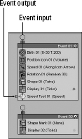
Once wired, all particles that are tested to be true are transferred to the new event node and are subject to the actions in the wired event node.
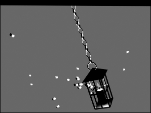
Tutorial: Moths chasing a light
Another cool feature that the Particle Flow interface makes available is the ability to have particles chase a target object. In this example, you use the Target event to make some annoying bugs follow a lantern's light.
To use Particle Flow to make several bugs chase a light, follow these steps:
- Open the Moths chasing light.max file from the Chap 41 directory on the CD.
This file includes a simple lantern created from primitives that is suspended from a chain and animated rocking back and forth. The file also includes a simple moth.
- Select Create Particles Particle Flow Source, and drag in the Front viewport to create the emitter icon. Click the Particle View button to open the Particle View interface.
- In the Event01 node, select the Birth01 action and set the Emit Stop to 100 with an Amount of 50.
- Drag the Position Object action from the Depot pane, and drop it on top of the Position Icon action to replace it. Select the new Position Object action, click the By List button under the Emitter Objects list in the Parameters pane, and select the Sphere01 object.
This sphere surrounds the lantern and is the source of the moths. It has a material with an Opacity setting of 0 applied so that it is not visible in the scene.
- Select the Rotation action in the Event01 node, and change the Orientation Matrix option to Speed Space Follow.
This rotates the moths as they follow the swinging lantern.
- Drag the Shape Instance action from the Depot pane, and drop it on top of the Shape action to replace it. Select the new Shape Instance action, click the Particle Geometry Object button in the Parameters pane, and select the moth object in the viewports.
- Drag the Find Target action from the Depot pane, and drop it at the bottom of the Event01 node. This adds a new Find Target icon to the viewports. Select the Find Target icon in the viewports, and move it to the lantern flame's position. Select Group Attach, and click the lantern object to add the Find Target icon to the lantern group. This makes the target move with the lantern. Enable the Use Cruise Speed option, and then set the Speed to 1000 with a Variation of 50 and the Accel Limit to 5000 with an Ease % of 50. You also need to enable the Follow Target Animation option.
- Drag the Material Dynamic from the Depot pane to the Event Display pane, and drop it outside the Event01 node to create a new node called Event02. In the Parameters pane, enable the Assign Material button and click the material button. Select the Flash material from the Material/Map Browser (select the Material Editor option to see the sample slot materials). Then drag a wire from Event01 to Event02.
- Drag the Age Test action from the Depot pane, and drop it below the Material Dynamic action. Then select Event Age from the drop-down list in the Parameters pane, and set the Test Value to 2.
- Finally, drag the Delete action from the Depot pane, and drop it away from the other events. Then wire Event02 to the new event node, and select the Selected Particles Only option in the Parameters pane.
Figure 41.21 shows several moths eagerly pursuing the swinging lantern.
FIGURE 41.21 All the moths in this scene are particles and are following a target linked to the lantern.
Debugging test actions
Any test action can be made to return a True or False value if you click the left (for True) or right (for False) side of the test action's icon in the Particle View interface. This lets you debug the particle flow. Tests set to be true show an icon with a green light, and tests set to be false show a red light icon.
Tutorial: Firing at a fleeing spaceship
Well, it is about time for a space scene, and we all know that lots of particles float around out in space—stars, asteroids, comets, and so forth. It's all great stuff to animate. For this scene, you use the Particle Flow feature to fire laser blasts on a fleeing spaceship.
To use Particle Flow to fire on a fleeing spaceship, follow these steps:
- Open the Fleeing spaceship.max file from the Chap 41 directory on the CD.
This file includes a spaceship model created by Viewpoint Datalabs that has been animated as if it were fleeing.
- Select Create Particles Particle Flow Source, and drag in the Front viewport to create the emitter. With the Select and Move (W) button selected, move the emitter until it is aligned with the end of the laser gun. Then click the Select and Link button, and drag from the emitter to the gun object to bind the emitter to the gun.
The emitter now moves with the animated laser gun.
- With the Particle Flow Source icon selected, open the Modify panel and click the Particle View button in the Setup rollout (or press the 6 key) to open the Particle View interface.
- In the Event01 node, select the Birth 03 event; in the Parameters panel, set the Emit Stop to 100 and the Amount to 50. This produces a laser blast every two frames. Click the blue dot in the lower-right corner of the Event node, and select a red color from the Color Selector that appears.
- Select Create Standard Primitives Cylinder, and drag in the Front viewport to create a Cylinder object. In the Hierarchy panel, select the Affect Pivot Only button and rotate the Cylinder's Pivot Point until its Y-axis points at the spaceship. Then in the Particle View window, drag the Shape Instance event from the depot and drop it on top of the Shape event in the Event 01 node. This replaces the Shape event with a Shape Instance event. In the Parameters rollout, click the Particle Geometry Object button and select the Cylinder object. Select the Rotation event, and delete it with the Delete key.
- Select Create Space Warps Deflectors SOmniFlect, and drag in the Top viewport to create a spherical deflector that encompasses the spaceship. Click the Select and Non-Uniform Scale button, and scale the X- and Z-axes until the deflector just fits around the spaceship. Then link the deflector Space Warp to the spaceship.
- In the Particle View window, drag the Collision event from the depot to the bottom of the Event 01 node. In the rollout, below the Deflectors list, click the Add button and select the SOmniFlect01 object surrounding the spaceship.
- Drag a Spawn event from the depot to the event display, and then connect the Collision event by dragging from its output to the input of the new Spawn event. Then click the color for the new event particles, and change it to orange. Select the Spawn 01 event, enable the Delete Parent option, and set the Offspring to 200 and the Variation % to 20. Then set the Inherited % to 50 with a Variation of 30.
- Drag the Delete event to the bottom of the Event 02 node, select the By Particle Age option, and set the Life Span to 20 and the Variation to 30. Drag a Shape event to the Event 02 node, and set the Shape to Sphere and the Size to 0.5.
- Finally, click the Play button to see the resulting animation.
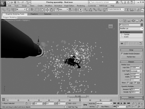
Figure 41.22 shows the final Particle View flow, and Figure 41.23 shows a frame of the animation in the viewport. You can still do several things to improve this animation, such as adding a Glow Render Effect to the laser blasts and using the Particle Age material with some transparency to improve the explosion's look.
FIGURE 41.22 The Particle View window shows the flow of the particles in the animation.
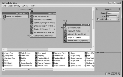
FIGURE 41.23 The spaceship is trying to outrun the laser blasts.
Summary
This chapter presented particle systems and showed how you can use them. The chapter also took a close look at each system, including Spray, Snow, Super Spray, Blizzard, PArray, PCloud, and Particle Flow. This chapter covered these topics:
- Learning about the various particle systems
- Creating a particle system for producing rain and snow
- Using the Super Spray particle system
- Working with MetaParticles
- Specifying an object to use as a particle and an object to use as an emitter
- Using the PArray and PCloud particle systems
- Using the Particle Age and Particle MBlur maps on particles
- Controlling and programming the flow of particles with the Particle Flow window
The next chapter explains working with Space Warps to add forces to a scene. These forces can be used to control the motion of objects in the scene.