
CHAPTER 6
Selecting Objects and Setting Object Properties
Selecting objects using toolbars and menus
Using named selection sets
Setting object properties
Hiding and freezing objects
Working with layers
Exploring the Scene Explorer
Now that you've learned how to create objects and had some practice, you've probably created more than you really need. To eliminate, move, or change the look of any objects, you first have to know how to select the object. Doing so can be tricky if the viewports are all full of objects lying on top of one another. Luckily, Max offers several selection features that make looking for a needle in a haystack easier.
Max offers many different ways to select objects. You can select by name, color, type, and even material. You also can use selection filters to make only certain types of objects selectable. And after you've found all the objects you need, you can make a selection set, which will allow you to quickly select a set of objects by name. Now where is that needle?
All objects have properties that define their physical characteristics, such as shape, radius, and smoothness, but objects also have properties that control where they are located in the scene, how they are displayed and rendered, and what their parent object is. These properties have a major impact on how you work with objects; understanding them can make objects in a scene easier to work with.
Selecting Objects
Max includes several methods for selecting objects—the easiest being simply clicking the object or dragging over it in one of the viewports. Selected objects turn white and are enclosed in brackets called selection brackets.
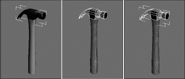
In addition to turning white and displaying selection brackets, several options allow you to mark selected objects. You can find these options in the Viewport Configuration dialog box (which you access with the Views ![]() Viewport Configuration menu command); they include selection brackets (keyboard shortcut, J) and edged faces (F4). Either or both of these options can be enabled, as shown in Figure 6.1. Another way to detect the selected object is that the object's axes appear at the object's pivot point. The Views
Viewport Configuration menu command); they include selection brackets (keyboard shortcut, J) and edged faces (F4). Either or both of these options can be enabled, as shown in Figure 6.1. Another way to detect the selected object is that the object's axes appear at the object's pivot point. The Views ![]() Shade Selected command turns on shading for the selected object in all viewports.
Shade Selected command turns on shading for the selected object in all viewports.
Caution
The Viewport Configuration dialog box also includes an option to Shade Selected Faces (F2), but this option shades only selected subobject faces.
FIGURE 6.1 Selected objects can be highlighted with selection brackets (left), edged faces (middle), or both (right).
With many objects in a scene, clicking directly on a single object, free from the others, can be difficult, but persistence can pay off. If you continue to click an object that is already selected, then the object directly behind the object you clicked is selected. For example, if you have a row of spheres lined up, you can select the third sphere by clicking three times on the first object.
Tip
In complicated scenes, finding an object is often much easier if it has a relevant name. Be sure to name your new objects using the Name and Color rollout. If a single object is selected, its name appears in the Name and Color rollout.
Selection filters
Before examining the selection commands in the Edit menu, I need to tell you about Selection Filters. With a complex scene that includes geometry, lights, cameras, shapes, and so on, selecting the exact object that you want can be difficult. Selection filters can simplify this task.
A selection filter specifies which types of objects can be selected. The Selection Filter drop-down list is located on the main toolbar to the left of the Select Object button. Selecting Shapes, for example, makes only shape objects available for selection. Clicking a geometry object with the Shape Selection Filter enabled does nothing.
The available filters include All, Geometry, Shapes, Lights, Cameras, Helpers, and Space Warps. If you're using Inverse Kinematics, you also can filter by Bone, IK Chain Object, and Point.
The Combos option opens the Filter Combinations dialog box, shown in Figure 6.2. From this dialog box, you can select combinations of objects to filter. These new filter combinations are added to the drop-down list. For example, to create a filter combination for lights and cameras, open the Filter Combinations dialog box, select Lights and Cameras, and click Add. The combination is listed as LC in the Current Combinations section, and the LC option is added to the drop-down list.
FIGURE 6.2 The Filter Combinations dialog box enables you to create a custom selection filter.
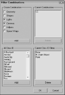
The Filter Combinations dialog box also includes a list of additional objects. Using this list, you can filter very specific object types, such as a Boolean object or a Box primitive. In fact, the Bone, IK Chain Object, and Point filters that appear in the default main toolbar drop-down list all come from this additional list.
Select buttons
On the main toolbar are several buttons used to select objects, shown in Table 6.1. The Select Object button looks like the arrow cursor. The other three buttons select and transform objects. They are Select and Move (W), Select and Rotate (E), and Select and Scale (R). These commands also are available on the quadmenu. The final selection button is the Select and Manipulate button. With this button, you can select and use special helpers such as sliders.
| Button | Description |
| Select Object (Q) | |
| Select and Move (W) | |
| Select and Rotate (E) | |
| Select and Scale (R) | |
| Select and Manipulate |
Cross-Reference
See Chapter 7, “Transforming Objects, Pivoting, Aligning, and Snapping,” for more details on the Select and Transform buttons.
Selecting with the Edit menu
The Edit menu includes several convenient selection commands. The Edit ![]() Select All (Ctrl+A) menu command does just what you would think it does: It selects all unfrozen and unhidden objects in the current scene of the type defined by the selection filter. The Edit
Select All (Ctrl+A) menu command does just what you would think it does: It selects all unfrozen and unhidden objects in the current scene of the type defined by the selection filter. The Edit ![]() Select None (Ctrl+D) menu command deselects all objects. You also can simulate this command by clicking in any viewport away from all objects. The Edit
Select None (Ctrl+D) menu command deselects all objects. You also can simulate this command by clicking in any viewport away from all objects. The Edit ![]() Select Invert (Ctrl+I) menu command selects all objects defined by the selection filter that are currently not selected and deselects all currently selected objects.
Select Invert (Ctrl+I) menu command selects all objects defined by the selection filter that are currently not selected and deselects all currently selected objects.
The Edit ![]() Select Similar (Ctrl+Q) command selects all objects that are similar to the current selection. If multiple objects are selected, the Select Similar command selects the objects that meet the criteria for being similar to each of the selected objects. Objects are similar if they meet one of the following criteria:
Select Similar (Ctrl+Q) command selects all objects that are similar to the current selection. If multiple objects are selected, the Select Similar command selects the objects that meet the criteria for being similar to each of the selected objects. Objects are similar if they meet one of the following criteria:
- Same object type such as lights, helpers, or Space Warps
- Same primitive object such as Sphere, Box, or Hedra
- Same modeling type such as Editable Spline, Editable Poly, or Editable Patch
- Imported objects from an AutoCAD DWG file that have the same style applied
- Same applied material
- Objects existing on the same layer
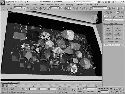
Figure 6.3 shows a treasure chest of Hedra gems created in Chapter 5. With a single object selected, choosing Edit ![]() Select Similar (Ctrl+Q) causes all Hedra primitive objects to be selected.
Select Similar (Ctrl+Q) causes all Hedra primitive objects to be selected.
FIGURE 6.3 The Select Similar command selects all Hedra objects.
Select by Name
Choosing Edit ![]() Select by
Select by ![]() Name opens the Select From Scene dialog box, which is a version of the Scene Explorer dialog box, except that you can't change any parameters. Clicking the Select by Name button on the main toolbar, positioned to the right of the Select Object button, or pressing the keyboard shortcut, H, also opens this dialog box.
Name opens the Select From Scene dialog box, which is a version of the Scene Explorer dialog box, except that you can't change any parameters. Clicking the Select by Name button on the main toolbar, positioned to the right of the Select Object button, or pressing the keyboard shortcut, H, also opens this dialog box.
Cross-Reference
The Scene Explorer dialog box is covered in detail later in this chapter.
You select objects by clicking their names in the list and then clicking OK, or by simply double-clicking a single item. To pick and choose several objects, hold down the Ctrl key while selecting. Holding down the Shift key selects a range of objects.
Select by Layer
The Layer Manager lets you separate all scene objects into layers for easy selection. The Edit ![]() Select by
Select by ![]() Layer command opens a simple dialog box listing the defined layers and lets you select a layer. All objects in the selected layer are then selected. The Layer Manager is covered in detail later in this chapter.
Layer command opens a simple dialog box listing the defined layers and lets you select a layer. All objects in the selected layer are then selected. The Layer Manager is covered in detail later in this chapter.
Select by Color
Choosing Edit ![]() Select by
Select by ![]() Color lets you click a single object in any of the viewports. All objects with the same color as the one you selected are selected. Even if you already have an object of that color selected, you still must select an object of the desired color. Be aware that this is the object color, not the applied material color. This command, of course, does not work on any objects without an associated color, such as Space Warps.
Color lets you click a single object in any of the viewports. All objects with the same color as the one you selected are selected. Even if you already have an object of that color selected, you still must select an object of the desired color. Be aware that this is the object color, not the applied material color. This command, of course, does not work on any objects without an associated color, such as Space Warps.
Select by Region
The Edit ![]() Selection Region command lets you select from one of two different methods for selecting objects in the viewport using the mouse. First, make sure that you're in select mode, and then click away from any of the objects and drag over the objects to select. The first method for selecting objects is Window Selection. This method selects all objects that are contained completely within the dragged outline. The Crossing Selection method selects any objects that are inside or overlapping the dragged outline. You also can access these two selection methods via the Window Selection buttons on the main toolbar—Window and Crossing, shown in Table 6.2.
Selection Region command lets you select from one of two different methods for selecting objects in the viewport using the mouse. First, make sure that you're in select mode, and then click away from any of the objects and drag over the objects to select. The first method for selecting objects is Window Selection. This method selects all objects that are contained completely within the dragged outline. The Crossing Selection method selects any objects that are inside or overlapping the dragged outline. You also can access these two selection methods via the Window Selection buttons on the main toolbar—Window and Crossing, shown in Table 6.2.
Tip
If you can't decide whether to use the Crossing or Window selection method, you can select to use both. The General panel of the Preference Settings dialog box provides an option to enable Auto Window/Crossing by Direction. When this option is enabled, you can select a direction, and the Crossing selection method is used for all selections that move from that direction. The Window selection method is used for all selections that move from the opposite direction. For example, if you select Left to Right for the Crossing selection method, then moving from Left to Right uses the Crossing selection method, and selecting from Right to Left uses the Window selection method.
TABLE 6.2 Window Selection Buttons
| Button | Description |
| Window | |
| Crossing |
You also can change the shape of the selection outline. The Selection Region button on the main toolbar to the left of the Selection Filter drop-down list includes flyout buttons for Rectangular, Circular, Fence, Lasso, and Paint Selection Regions, shown in Table 6.3.
The Rectangular selection method lets you select objects by dragging a rectangular section (from corner to corner) over a viewport. The Circular selection method selects objects within a circle that grows from the center outward. The Fence method lets you draw a polygon-shaped selection area by clicking at each corner. Simply double-click to finish the fenced selection. The Lasso method lets you draw by freehand the selection area. The Paint method lets you choose objects by painting an area. All objects covered by the paint brush area are selected.
TABLE 6.3 Shape-Shifting Selection Region Buttons
| Button | Description |
| Rectangular | |
| Circular | |
| Fence | |
| Lasso | |
| Paint |
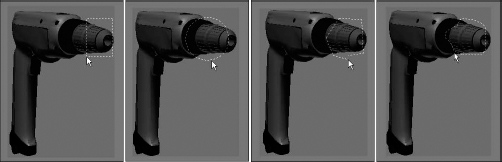
Pressing the Q keyboard shortcut selects the Select Object mode in the main toolbar, but repeated pressing of the Q keyboard shortcut cycles through the selection methods. Figure 6.4 shows each of the selection methods.
FIGURE 6.4 The drill's front is selected using the Rectangular, Circular, Fence, and Lasso selection methods.
Selecting multiple objects
As you work with objects in Max, you'll sometimes want to apply a modification or transform to several objects at once. You can select multiple objects in several ways. Using the Edit ![]() Select by
Select by ![]() Name command, the Select by Name main toolbar button, or by pressing the H key, you can open the Select From Scene dialog box. With the Select From Scene dialog box open, you can choose several objects from the list using the standard Ctrl and Shift keys. Holding down the Ctrl key selects or deselects multiple list items, but holding down the Shift key selects all consecutive list items between the first selected and the second selected items.
Name command, the Select by Name main toolbar button, or by pressing the H key, you can open the Select From Scene dialog box. With the Select From Scene dialog box open, you can choose several objects from the list using the standard Ctrl and Shift keys. Holding down the Ctrl key selects or deselects multiple list items, but holding down the Shift key selects all consecutive list items between the first selected and the second selected items.
The Ctrl key also works when selecting objects in the viewport using one of the main toolbar Select buttons. You can tell whether you're in select mode by looking for a button that's highlighted yellow. If you hold down the Ctrl key and click an object, then the object is added to the current selection set. If you drag over multiple objects while holding down the Ctrl key, then all items in the dragged selection are added to the current selection set.
The Alt key deselects objects from the current selection set, which is opposite of what the Ctrl key does.
If you drag over several objects while holding down the Shift key, then the selection set is inverted. Each item that was selected is deselected, and vice versa.
Object hierarchies are established using the Link button on the main toolbar. You can select an entire hierarchy of objects by double-clicking its parent object. You also can select multiple objects within the hierarchy. When you double-click an object, any children of that object are also selected. When an object with a hierarchy is selected, the Page Up and Page Down keys select the next object up or down the hierarchy.
Another way to select multiple objects is by dragging within the viewport using the Window and Crossing Selection methods discussed previously in the “Select by Region” section.
Caution
Although the Move, Rotate, and Scale buttons may also be used to select objects, they can cause problems when selecting multiple objects. If you are selecting multiple objects with the Select and Move tool and you accidentally drag the mouse while moving to the next item, then the entire selection is moved out of place. You can use the Undo feature to return it to its original position. To prevent this from happening, use the Select Tool when selecting multiple objects.
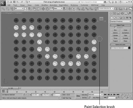
Using the Paint Selection Region tool
The Paint Selection Region tool is the last flyout button under the Rectangle Selection Region button. Using this tool, you can drag a circular paint brush area over the viewports, and all objects or subobjects underneath the brush are selected.
The size of the Selection Paint brush is shown as a circle when the tool is selected and may be changed using the Paint Selection Brush Size field in the General panel of the Preference Settings dialog box. Right-clicking the Paint Selection Region button on the main toolbar automatically opens the Preference Settings dialog box. Figure 6.5 shows how the Paint Selection Region may be used to select several spheres by dragging over them.
FIGURE 6.5 The Paint Selection Region tool makes it easy to select spheres by dragging.
Tutorial: Selecting objects
To practice selecting objects, you'll work with a simple model of the lion toy. When you're finished, you can throw this model to your dog for a chew toy.
To select objects, follow these steps:
- Open the Lion toy.max scene, which you can find in the Chap 06 directory on the CD.
- Click the Select Object button (or press the Q key), and click the lion's body in one of the viewports.
In the Command Panel, the name for this object, lion, is displayed in the Name and Color rollout.
- Click the Select and Move button (or press the W key), click the lion's body, and drag in the Perspective viewport to the right.
As you can see, the lion's head and body form an object independent of the other parts of the lion object. Moving it separates it from the rest of the model's parts.
- Choose Edit
 Undo Move (or press Ctrl+Z) to piece the lion back together.
 - With the Select and Move tool still selected, drag an outline around the entire lion in the Top view to select all the lion parts, and then click and drag the entire lion again.
This time, the entire lion moves as one entity, and the name field displays Multiple Selected.
- Open the Select Objects dialog box by clicking the Select by Name button on the main toolbar (or by pressing the H key).
All the individual parts that make up this model are listed.
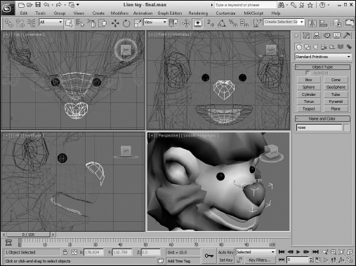
- Double-click the nose object listed in the dialog box.
The Select Objects dialog box automatically closes, and the nose object becomes selected in the viewports.
Figure 6.6 shows our lion friend with just its nose object selected. Notice that the name of the selected object in the Name and Color rollout says “nose.”
FIGURE 6.6 A lion cartoon character with its white selected nose
Locking selection sets
If you've finally selected the exact objects that you want to work with, you can disable any other selections using the Selection Lock toggle button on the Status Bar. (It looks like a lock.) When this button is enabled, it is colored yellow, and clicking objects in the viewports won't have any effect on the current selection. The keyboard shortcut toggle for this command is the spacebar.
In Photoshop and Illustrator, the spacebar is the keyboard shortcut to pan, but in Max it locks the current selection. If you accidentally lock the current selection, then you can't select any other objects until the lock is removed.
Using named selection sets
With a group of selected objects, you can establish a selection set. Once it's established as a selection set, you can recall this group of selected objects at any time by selecting its name from the Named Selection Set drop-down list on the main toolbar or by opening the Named Selection Sets dialog box, shown in Figure 6.7.
![]() You can access this dialog box using the Edit Named Selection Sets button on the main toolbar or by selecting the Edit
You can access this dialog box using the Edit Named Selection Sets button on the main toolbar or by selecting the Edit ![]() Manage Selection Sets menu command. To establish a selection set, type a name in the Named Selection Set drop-down list toward the right end of the main toolbar or use the dialog box.
Manage Selection Sets menu command. To establish a selection set, type a name in the Named Selection Set drop-down list toward the right end of the main toolbar or use the dialog box.
FIGURE 6.7 The Edit Named Selections dialog box lets you view and manage selection sets.
You also can create named selection sets for subobject selections. Be aware that these subobject selection sets are available only when you're in subobject edit mode and only for the currently selected object.
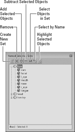
Editing named selections
After you've created several named selection sets, you can use the Named Selections Sets dialog box to manage the selection sets. The buttons at the top let you create and delete sets, add or remove objects from a set, and select and highlight set objects. You also can move an object between sets by dragging its name to the set name to which you want to add it. Dragging one set name onto another set name combines all the objects from both sets under the second set name. Double-clicking a set name selects all the objects in the set.
Isolating the current selection
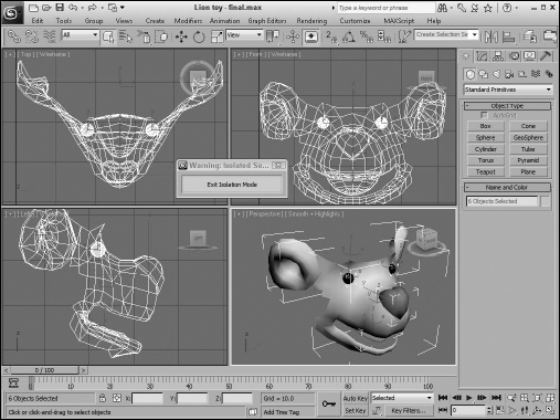
The Tools ![]() Isolate Selection (Alt+Q) menu command hides all objects except for the selected object. It also zooms to extents on the object in the active viewport. And it opens a simple dialog box with an Exit Isolation button in it. Clicking this button or selecting the Isolate command again exits isolation mode and displays all the objects again.
Isolate Selection (Alt+Q) menu command hides all objects except for the selected object. It also zooms to extents on the object in the active viewport. And it opens a simple dialog box with an Exit Isolation button in it. Clicking this button or selecting the Isolate command again exits isolation mode and displays all the objects again.
Isolate Selection mode is very convenient for working on a certain area. Figure 6.8 shows the Isolate Selection mode for a selection set that includes all elements of the lion toy's face.
FIGURE 6.8 Isolated Selection mode lets you focus on the details of the selected object.
Selecting objects in other interfaces
In addition to selecting objects in the viewports, you can use many of the other interfaces and dialog boxes to select objects. For example, the Material Editor includes a button that selects all objects in a scene with the same material applied.
![]() The Select by Material button opens the Select Object dialog box with all objects that use the selected material highlighted.
The Select by Material button opens the Select Object dialog box with all objects that use the selected material highlighted.
Another way to select objects is in the Track View, which can be opened using the Graph Editors ![]() New Track View menu command. To view all the objects, click the + sign that precedes the Objects track. You can identify the Objects track by a small, yellow cube. A hierarchy of all the objects in a scene is displayed. At the bottom left of the Track View window is the Select by Name text field. Typing an object name in this field automatically selects the object's track in the editor's window, but not in the viewport. Clicking the yellow cube icon selects the object in the viewport.
New Track View menu command. To view all the objects, click the + sign that precedes the Objects track. You can identify the Objects track by a small, yellow cube. A hierarchy of all the objects in a scene is displayed. At the bottom left of the Track View window is the Select by Name text field. Typing an object name in this field automatically selects the object's track in the editor's window, but not in the viewport. Clicking the yellow cube icon selects the object in the viewport.
A third interface that you can use to select objects is the Schematic View, which is opened using the Graph Editors ![]() New Schematic View menu command. It offers a hierarchical look at your scene and displays all links and relationships between objects. Each object in the Schematic View is displayed as a rectangular node.
New Schematic View menu command. It offers a hierarchical look at your scene and displays all links and relationships between objects. Each object in the Schematic View is displayed as a rectangular node.
To select an object in the viewport, find its rectangular representation in the Schematic View and simply click it. To select multiple objects in the Schematic View, you need to enable Sync Selection mode with the Select ![]() Sync Selection command in the Schematic View menu and then drag an outline over all the rectangular nodes that you want to select.
Sync Selection command in the Schematic View menu and then drag an outline over all the rectangular nodes that you want to select.
The Schematic View also includes the Select by Name text field, just like the Curve Editor, for selecting an object by typing its name.
Cross-Reference
The Material Editor is covered in detail in Chapter 15, “Using the Slate Material Editor”; the Track View is covered in Chapter 36, “Working with the F-Curve Editor in the Track View”; and the Schematic View interface is covered in Chapter 25, “Building Complex Scenes with Containers, XRefs, and the Schematic View.”
Setting Object Properties
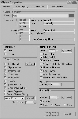
After you select an object or multiple objects, you can view their object properties by choosing Edit ![]() Object Properties. Alternatively, you can right-click the object and select Properties from the pop-up menu. Figure 6.9 shows the Object Properties dialog box. This dialog box includes four panels—General, Advanced Lighting, mental ray, and User Defined.
Object Properties. Alternatively, you can right-click the object and select Properties from the pop-up menu. Figure 6.9 shows the Object Properties dialog box. This dialog box includes four panels—General, Advanced Lighting, mental ray, and User Defined.
Viewing object information
For a single object, the General panel of the Object Properties dialog box lists details about the object in the Object Information section. These details include the object's name; color; extent distances from the origin along the X-, Y-, and Z-axes; number of vertices and faces; the object's parent; the object's Material Name; the number of children attached to the object; the object's group name if it's part of a group; and the layer on which the object can be found. All this information (except for its name and color) is for display only and cannot be changed.
FIGURE 6.9 The Object Properties dialog box displays valuable information about a selected object.
Note
The two fields under the Vertices and Faces are used only when the properties for a Shape are being displayed. These fields show the number of Shape Vertices and Shape Curves.
If the properties for multiple objects are to be displayed, the Object Properties dialog box places the text “Multiple Selected” in the Name field. The properties that are in common between all these objects are displayed. With multiple objects selected, you can set their display and rendering properties all at once.
The Object Properties dialog box can be displayed for all geometric objects and shapes, as well as for lights, cameras, helpers, and Space Warps. Not all properties are available for all objects.
Cross-Reference
The Hide and Freeze options included in the Interactivity section are covered later in this chapter in the “Hiding and Freezing Objects” section.
Setting display properties
Display properties don't affect how an object is rendered, only how it is displayed in the viewports. In this section, along with the Rendering Control and Motion Blur sections, are three By Object/By Layer toggle buttons. If the By Object button is displayed, then options can be set for the selected object, but if the By Layer option is enabled, then all options become disabled and the object gets its display properties from the layer settings found in the Layer Manager.
Note
You also can find and set the same Display Properties that are listed in the Object Properties dialog box in the Display Properties rollout of the Display panel in the Command Panel and in the Display Floater.
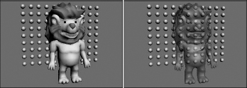
The See-Through option causes shaded objects to appear transparent. This option is similar to the Visibility setting in the Rendering Control section, except that it doesn't affect the rendered image. It is only for displaying objects in the viewports. This option really doesn't help in wireframe viewports. Figure 6.10 shows the lion toy model with spheres behind it with and without this option selected.
FIGURE 6.10 The See-Through display property can make objects transparent in the viewports.
Many of these display properties can speed up or slow down the viewport refresh rates. For example, Display as Box increases the viewport update rate dramatically for complex scenes, but at the expense of any detail. This setting can be useful to see how the objects generally fit in comparison to one another. This option also can be accessed from the Viewport Configuration dialog box or from the Viewport name right-click pop-up menu, but the Object Properties dialog box lets you set this option for a single object instead of for the entire viewport.
When the Backface Cull option is enabled, it causes the faces on the backside of the object to not be displayed. Max considers the direction that each normal is pointing and doesn't display a face if its normal points away from the view. A normal is a vector that extends perpendicular to the face and is used to determine the orientation of individual faces. This option produces the same result of the Force 2-Sided option in the Viewport Configuration dialog box, except that it can be applied to a single object and not the entire viewport. This display option works only in wireframe viewports.
The Edges Only option displays only the edges of each object when the viewport is set to Wireframe mode. When Edges Only is not selected, a dashed line indicates the junction of individual faces.
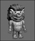
When the Vertex subobject mode is selected for an object, all vertices for the selected object appear as blue + signs. The Vertex Ticks option displays all object vertices in this same way without requiring the Vertex subobject mode. Figure 6.11 shows the lion toy mesh with this option enabled. The Trajectory option displays the animation path that the object follows. You also can make the trajectory of the selected object appear without enabling the Trajectory option by selecting the Trajectories button in the Motion panel.
FIGURE 6.11 The Vertex Ticks option displays all vertices as small, blue tick marks.
The Trajectory option displays any animated motions as a spline path.
Cross-Reference
To learn more about using animated motion paths, see Chapter 21, “Understanding Animation and Keyframes.”
The Ignore Extents option causes an object to be ignored when you are using the Zoom Extents button in the Viewport Navigation controls. For example, if you have a camera or light positioned at a distance from the objects in the scene, then anytime you use the Zoom Extents All button, the center objects are so small that you cannot see them because the Zoom Extents needs to include the distance light. If you set the Ignore Extent option for the camera or light, then the Zoom Extents All button zooms in on just the geometry objects.
When objects are frozen, they appear dark gray, but if the Show Frozen in Gray option is disabled, then the object appears as it normally does in the viewport. The Never Degrade option causes the object to be removed from the Adaptive Degradation settings used to maintain a given frame rate to get the animation timing right.
The Vertex Channel Display option displays the colors of any object vertices that have been assigned colors. You can select to use Vertex Color, Vertex Illumination, Vertex Alpha, Map Channel Color, or Soft Selection Color. The Shaded button causes the meshes to be shaded by the vertex colors. If the Shaded button is disabled, the object is unshaded. You can assign vertex colors only to editable meshes, editable polys, and editable patches. If the Map Channel Color option is selected, you can specify the Map Channel.
Cross-Reference
For more information about vertex colors, check out Chapter 34, “Creating Baked Textures and Normal Maps.”
Setting rendering controls
In the Object Properties dialog box, the Rendering Controls section includes options that affect how an object is rendered.
The Visibility spinner defines a value for how opaque (nontransparent) an object is. A value of 1 makes the object completely visible. A setting of 0.1 makes the object almost transparent. The Inherit Visibility option causes an object to adopt the same visibility setting as its parent.
The Renderable option determines whether the object is rendered. If this option isn't selected, then the rest of the options are disabled because they don't have any effect if the object isn't rendered. The Renderable option is useful if you have a complex object that takes a while to render. You can disable the renderability of the single object to quickly render the other objects in the scene.
You can use the Visible to Camera and Visible to Reflection/Refraction options to make objects invisible to the camera or to any reflections or refractions. This feature can be useful when you are test-rendering scene elements and raytraced objects.
Tip
If an object has the Visible to Camera option disabled and the Cast Shadows option enabled, then the object isn't rendered, but its shadows are.
The Receive Shadows and Cast Shadows options control how shadows are rendered for the selected object. The Apply Atmospherics options enable or disable rendering atmospherics. Atmospheric effects can increase the rendering time by a factor of 10, in some cases.
Cross-Reference
Atmospheric and render effects are covered in Chapter 46, “Using Atmospheric and Render Effects.”
The Render Occluded Objects option causes the rendering engine to render all objects that are hidden behind the selected object. The hidden or occluded objects can have glows or other effects applied to them that would show up if rendered.
You use the G-Buffer Object Channel value to apply Render or Video Post effects to an object. By matching the Object Channel value to an effect ID, you can make an object receive an effect. A g-buffer is a temporary bit of memory used to process an image that isn't interrupted by transferring the data to the hard disk.
Cross-Reference
The Video Post interface is covered in Chapter 49, “Compositing with Render Elements and the Video Post Interface.”
Enabling Motion Blur
You also can set Motion Blur from within the Object Properties dialog box. The Motion Blur effect causes objects that move fast (such as the Road Runner) to be blurred (which is useful in portraying speed). The render engine accomplishes this effect by rendering multiple copies of the object or image.
Cross-Reference
More information on these blur options is in Chapter 23, “Rendering a Scene and Enabling Quicksilver.”
The Object Properties dialog box can set two different types of Motion Blur: Object and Image. Object motion blur affects only the object and is not affected by the camera movement. Image motion blur applies the effect to the entire image and is applied after rendering.
A third type of Motion Blur is called Scene Motion Blur and is available in the Video Post interface. See Chapter 49, “Compositing with Render Elements and the Video Post Interface,” for information on using Scene Motion Blur.
You can turn the Enabled option on and off as an animation progresses, allowing you to motion blur select sections of your animation sequence. The Multiplier value is enabled only for the Image Motion Blur type. It is used to set the length of the blur effect. The higher the Multiplier value, the longer the blurring streaks. The Motion Blur settings found in the Object Properties dialog box can be overridden by the settings in the Render Scene dialog box.
Caution
If the Motion Blur option in the Object Properties dialog box is enabled but the Motion Blur option in the Renderer panel of the Render Scene dialog box is disabled, then motion blur will not be included in the final rendered image.
Using the Advanced Lighting and mental ray panels
The second and third panels in the Object Properties dialog box contain object settings for working with Advanced Lighting and the mental ray renderer. Using the settings in the Advanced Lighting panel, you can exclude an object from any Advanced Lighting calculations, set an object to cast shadows and receive illumination, and set the number of refine iterations to complete.
The mental ray panel includes options for making an object generate and/or receive caustics and global illumination.
Cross-Reference
Advanced Lighting is covered in Chapter 45, “Working with Advanced Lighting, Light Tracing, and Radiosity,” and the mental ray renderer is covered in Chapter 47, “Rendering with mental ray and iray.”
Using the User-Defined panel
The User-Defined panel contains a simple text window. In this window, you can type any sort of information. This information is saved with the scene and can be referred to as notes about an object.
Hiding and Freezing Objects
Hidden and frozen objects cannot be selected, and as such they cannot be moved from their existing positions. This becomes convenient when you move objects around in the scene. If you have an object in a correct position, you can freeze it to prevent it from being moved accidentally or you can hide it from the viewports completely. A key difference between these modes is that frozen objects are still rendered, but hidden objects are not.
You can hide and freeze objects in several ways. You can hide or freeze objects in a scene by selecting the Hide or Freeze options in the Object Properties dialog box. You also can hide and freeze objects using the Display Floater dialog box, which you access by choosing Tools ![]() Display Floater.
Display Floater.
Several keyboard shortcuts can be used to hide specific objects. These shortcuts are toggles, so one press makes the objects disappear and another press makes them reappear. Object types that can be hidden with these shortcuts include cameras (Shift+C), geometry (Shift+G), grids (G), helpers (Shift+H), lights (Shift+L), particle systems (Shift+P), shapes (Shift+S), and Space Warps (Shift+W).
The Hide option makes the selected object in the scene invisible, and the Freeze option turns the selected object dark gray (if the Show Frozen in Gray option in the Object Properties dialog box is enabled) and doesn't allow it to be transformed or selected. You cannot select hidden objects by clicking in the viewport.
Note
When you use the Zoom Extents button to resize the viewports around the current objects, hidden objects aren't included.
Using the Display Floater dialog box
The Display Floater dialog box includes two tabs: Hide/Freeze and Object Level. The Hide/Freeze tab splits the dialog box into two columns, one for Hide and one for Freeze. Both columns have similar buttons that let you hide or freeze Selected or Unselected objects, By Name or By Hit. The By Name button opens the Select Objects dialog box (which is labeled Hide or Freeze Objects). The By Hit option lets you click in one of the viewports to select an object to hide or freeze. Each column also has additional buttons to unhide or unfreeze All objects, By Name, or in the case of Freeze, By Hit. You also can select an option to Hide Frozen Objects.
Note
Other places to find the same buttons found in the Display Floater are the Hide and Freeze rollouts of the Display panel of the Command Panel and in the right-click quadmenu.
The Object Level panel of the Display Floater lets you hide objects by category such as All Lights or Cameras. You also can view and change many of the Display Properties that are listed in the Object Properties dialog box.
Figure 6.12 shows the Hide/Freeze and Object Level panels of the Display Floater dialog box.
Using the Display panel
If you took many of the features of the Display Floater and the Object Properties dialog box and mixed them together, the result would be the Display panel. You access this panel by clicking the fifth icon from the left in the Command Panel (the icon that looks like a monitor screen).
The first rollout in the Display panel, shown in Figure 6.13, is the Display Color rollout. This rollout includes options for setting whether Wireframe and Shaded objects in the viewports are displayed using the Object Color or the Material Color.
FIGURE 6.12 The Display Floater dialog box includes two panels: Hide/Freeze and Object Level.
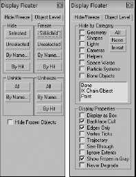
FIGURE 6.13 The Display panel includes many of the same features as the Display Floater and the Object Properties dialog box.

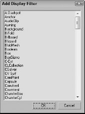
The panel also includes a Hide by Category rollout. Using this rollout, you can add new categories that will appear in the Object Level panel of the Display Floater. To add a new category, click the Add button of the Hide by Category rollout. The Add Display Filter list appears, as shown in Figure 6.14. From this list, you can choose specific object categories to add to the Hide by Category list.
FIGURE 6.14 From this dialog box, you can add new categories to the Hide by Category list.
The Display panel also includes Hide and Freeze rollouts that include the same buttons and features as the Hide/Freeze panel of the Display Floater. You also find a Display Properties rollout that is the same as the list found in the Display Floater's Object Level panel and the Object Properties dialog box.
The Link Display rollout at the bottom of the Display panel includes options for displaying links in the viewports. Links are displayed as lines that extend from the child to its parent object. Using the Link Replaces Object option, you can hide the objects in the viewport and see only the links.
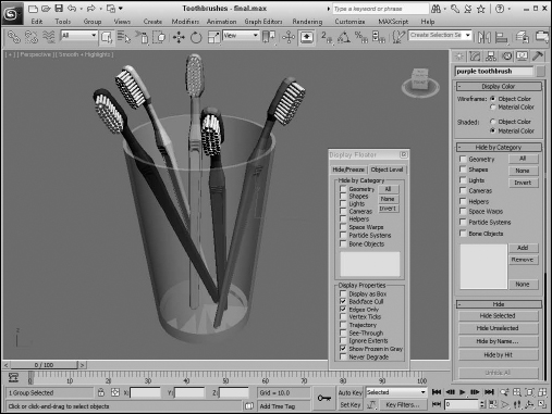
Tutorial: Hidden toothbrushes
In this example, I've hidden several toothbrushes in the scene, and your task is to find them. To find the hidden objects, follow these steps:
- Open the Toothbrushes.max scene file.
This file appears to contain only a single toothbrush, but it really contains more. Can you find them? The toothbrush model was created by Viewpoint Datalabs. You can find it in the Chap 06 directory on the CD.
- Locate the hidden object in the scene by opening the Display Floater (choose Tools Display Floater).
- In the Display Floater, select the Hide/Freeze tab. In the Unhide section, click the Name button.
The Unhide Objects dialog box appears, which lists all the hidden objects in the scene.
- Select the green toothbrush object from the list, and click the Unhide button.
The Unhide Objects dialog box closes, and the hidden objects become visible again.
Note
Notice that the Display Floater is still open. That's because it's modeless. You don't need to close it to keep working.
- To see all the remaining objects, click the All button in the Unhide column of the Display Floater.
Figure 6.15 shows the finished scene with all toothbrushes visible.
FIGURE 6.15 Here are toothbrushes for the whole family; just remember which color is yours.
Using Layers
So what does 3ds Max have in common with a wedding cake? The answer is layers. Layers provide a way to separate scene objects into easy-to-select and easy-to-work-with groupings. These individual layers have properties that can then be turned on and off.
Cross-Reference
Animation sequences also can be split into layers using the Animation Layers. You can learn more about these layers in Chapter 35, “Using Animation Layers, Modifiers, and Complex Controllers.”
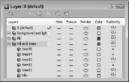
Using the Layer Manager
You create, access, and manage layers through the Layer Manager dialog box, shown in Figure 6.16. This dialog box is a floater that can remain open as you work with objects in the viewports. You can access the Layer Manager using the Tools ![]() Manage Layers menu command, by clicking the Layer Manager button on the main toolbar, or by clicking the same button in the Layers toolbar.
Manage Layers menu command, by clicking the Layer Manager button on the main toolbar, or by clicking the same button in the Layers toolbar.
Cross-Reference
These layers are different from Animation Layers that are used to break an animation sequence into several different parts that can be blended together. Animation Layers are covered in Chapter 35, “Using Animation Layers, Modifiers, and Complex Controllers.”
FIGURE 6.16 The Layer Manager lists all the layers and the objects contained within each layer.
After you've set up your layers, you can control them using the Layers toolbar, shown in Figure 6.17, rather than having the Layer Manager open. You can access the Layers toolbar by right-clicking the main toolbar away from the buttons and selecting the Layers toolbar from the pop-up menu or by selecting the Customize ![]() Show UI
Show UI ![]() Floating Toolbars menu command.
Floating Toolbars menu command.
FIGURE 6.17 Use the Layers toolbar to set the active layer.
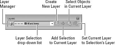
Table 6.4 lists the buttons found in the Layer Manager.
TABLE 6.4 Layer Manager Buttons
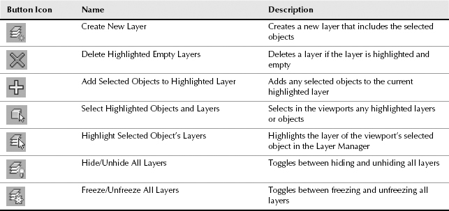
With the Layer Manager open, you can create new layers by clicking the Create New Layer button. This adds a new layer to the manager, names it “Layer01,” and includes any selected objects as part of the layer. If you click the layer's name, you can rename it. Layer 0 is the default layer to which all objects are added, if other layers don't exist. Layer 0 cannot be renamed.
Note
Although you can rename layers in the Layer Manager, you cannot use the Layer Manager to rename objects. To rename an object from the Layer Manager, simply click the object's icon to open the Object Properties dialog box, where you can change the object's name.
Creating a new layer automatically makes the new layer the current layer as denoted by the check mark in the first column of the Layer Manager. All new objects that are created are automatically added to the current layer. Only one layer can be current at a time, but several layers or objects can be highlighted. To highlight a layer, click it in the Layer Manager. Highlighted layers are highlighted in yellow.
A highlighted layer can be deleted with the Delete Highlighted Empty Layer button, but only if it is not the current layer and it doesn't contain any objects.
Newly created objects are added to the current layer (the one marked with a check mark in the first column of the Layer Manager). If you forget to select the correct layer for the new objects, you can select the objects in the viewports, highlight the correct layer, and use the Add Selected Objects to Highlighted Layer button to add the objects to the correct layer.
Every object can be added only to a single layer. You cannot add the same object to multiple layers.
The Select Highlighted Objects and Layers button selects the highlighted layers (and objects) in the viewports. This provides a way to select all the objects on a given layer. If an object in the viewports is selected, you can quickly see which layer it belongs to with the Highlight Selected Object's Layers button.
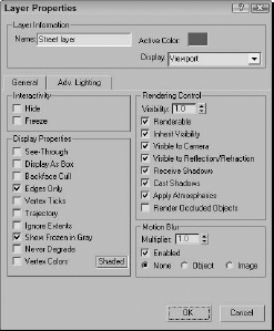
If you expand the layer name in the Layer Manager, you see a list of all the objects contained within the layer. If you click the Layer icon (to the left of the layer's name), the Layer Properties dialog box, shown in Figure 6.18, opens. Clicking the Object icon opens the Object Properties dialog box. You also can open either of these dialog boxes by right-clicking the layer name and selecting either from the pop-up menu.
FIGURE 6.18 The Layer Properties dialog box is similar to the Object Properties dialog box, but it applies to the entire layer.
Using the layer list
The main section of the Layer Manager (and repeated in the Layers toolbar) is the layer list and its columns, which allow you to turn certain properties on and off. The properties in the columns include Hide, Freeze, Render, Color, and Radiosity. If a property is enabled, a simple icon is displayed; if disabled, a dash is displayed. If an object is set to get its property from the layer (by clicking the ByLayer button in the Object Properties dialog box), then a dot icon is displayed. Individual objects within a layer can have different properties. You can sort the column properties by clicking the column head.
You can toggle these properties on and off by clicking them. You also can set these properties in the Layers toolbar. The Hide toggle determines whether the layer's objects are visible in the viewports. The Freeze toggle makes objects on a layer unselectable. The Render toggle enables the layer's objects to be rendered. The Color toggle sets the layer color. Layer 0 is set to assign random colors and cannot be changed. The Radiosity toggle includes the layer's objects in the radiosity calculations.
The Layer Manager also includes a right-click pop-up menu that includes many of the same commands found as buttons, but a unique set of commands found in the right-click pop-up menu are the Cut and Paste commands. With these commands, you can select objects in one layer to cut and paste into another layer.
Caution
If multiple objects are selected within the Layer Manager, then right-clicking an object's name deselects all the selected objects. To maintain the current selection, right-click within the Layer Manager, away from the Layers column.
Tutorial: Dividing a scene into layers
As a scene begins to come together, you'll start to find that it is difficult to keep track of all the different pieces. This is where the layers interface can really help. In this example, you take a simple scene and divide it into several layers.
To divide a scene into layers, follow these steps:
- Open the Elk on hill layers.max scene file.
You can find it in the Chap 06 directory on the CD. This file includes an Elk model created by Viewpoint Datalabs.
- Select Tools Manage Layers to open the Layer Manager.
- With no objects selected, click the Create New Layer button and name the layer Hill and trees. Click the Create New Layer button again, and name this layer Elk. Click the Create New Layer button again, and create a layer named Background and light. The Layer Manager now includes four layers, including layer 0.
- In the Layer Manager, click the first column for the Elk layer to make it the current layer. With the Edit Select All (Ctrl+A) menu command, select all objects in the scene and click the Add Selected Objects to Highlighted Layer button in the Layer Manager.
- Expand the Elk layer by clicking the + icon to the left of its name.
This displays all the objects within this layer.
- Select all the trees and the hill objects by holding down the Ctrl key and clicking each object's name in the Layer Manager. Then right-click away from the names, and select Cut from the pop-up menu. Then select the Hill and trees layer, and select Paste from the right-click pop-up menu.
- Select the background and light objects from within the Elk layer, and click the Select Highlighted Objects and Layers button. Then select the Background and light layer, and click the Add Selected Objects to Highlighted Layer button to move the background and light objects to the correct layer.
You can now switch between the layers, depending on which one you want to add objects to or work on, and you can change properties as needed. For example, to focus on the deer object, you can quickly hide the other layers using the Layer Manager.
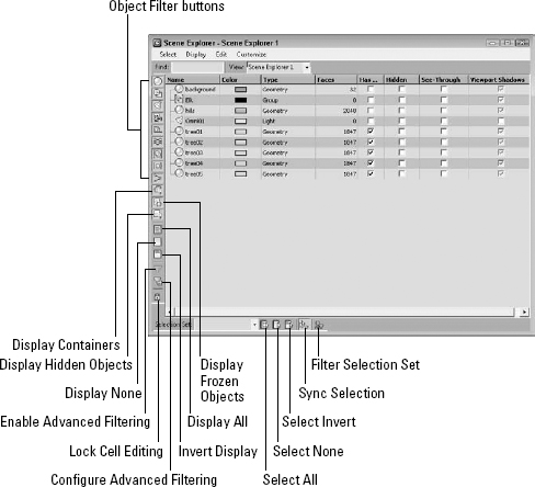
Using the Scene Explorer
The Scene Explorer is a one-stop shop for all scene objects and display properties. It displays all the objects in the scene in a hierarchical list along with various display properties. It allows you to filter the display so you can see just what you want and customize the display so only those properties you want to see are visible. The Scene Explorer also lets you select, rename, hide, sort, freeze, link, and delete objects and change the object color.
A Scene Explorer dialog box, shown in Figure 6.19, is opened using the Tools ![]() New Scene Explorer menu command (Alt+Ctrl+O). Each subsequent Scene Explorer view is numbered, but these individual views also can be named using the View field at the top of each Scene Explorer window. Each new or named view can be recalled with the Tools
New Scene Explorer menu command (Alt+Ctrl+O). Each subsequent Scene Explorer view is numbered, but these individual views also can be named using the View field at the top of each Scene Explorer window. Each new or named view can be recalled with the Tools ![]() Saved Scene Explorers menu, and the Tools
Saved Scene Explorers menu, and the Tools ![]() Manage Scene Explorers opens a simple dialog box where you can Load, Save, Delete, and Rename the saved views.
Manage Scene Explorers opens a simple dialog box where you can Load, Save, Delete, and Rename the saved views.
Note
Scene Explorer views are automatically saved and reloaded with the Max file.
FIGURE 6.19 The Scene Explorer dialog box displays all scene objects and their display properties.
All scene objects in the Scene Explorer are listed in hierarchical order with children objects indented under their parent objects. You can expand or contract children objects by clicking the plus (+) or minus (-) icon to the left of the parent object.
Selecting and filtering objects
If you click an object in the Scene Explorer dialog box, the object row is highlighted. Holding down the Ctrl key lets you click to select multiple objects, or you can use the Shift key to select a range of adjacent objects. Selected objects also can be removed from the current selection with the Ctrl key held down.
The Select menu also includes options for selecting objects. The All (Ctrl+A), None (Ctrl+D), and Invert (Ctrl+I) menu commands work as expected, selecting all objects, deselecting all objects, and selecting the inverse of the current selection. You also can access these commands using the buttons at the bottom of the dialog box.
The Select Children (Ctrl+C) option causes all children objects to automatically be selected when the parent is selected. The Select Influences option selects all influence objects that are attached to the selected objects. An influence object is an object that controls or shapes another object. For example, when a sphere is constrained to follow an animation path, the path is an influence object to the sphere. Another example is a skin mesh being influenced by a biped rig. The Select Dependencies option selects any objects that are dependent on the selected object, such as an instance and reference.
When the Select ![]() Sync Selection option is enabled, any objects selected in the Scene Explorer dialog box are automatically selected in the viewports also. This also works in reverse, causing any objects selected in the viewport to be selected in the Scene Explorer dialog box.
Sync Selection option is enabled, any objects selected in the Scene Explorer dialog box are automatically selected in the viewports also. This also works in reverse, causing any objects selected in the viewport to be selected in the Scene Explorer dialog box.
The Scene Explorer recognizes any defined Selection Sets and lets you select these sets from the drop-down list at the bottom of the interface.
The Display toolbar includes several object type icons. The yellow icons are selected and allowed to be viewed in the Scene Explorer. To filter out a specific object type, disable its icon, and then all objects of that type are no longer displayed in the list. These same commands are available in the Display ![]() Object Types menu.
Object Types menu.
The Display menu includes some additional commands for displaying children, influences, and dependencies. You also have an option to Display in Track View. This option opens the Track View with the selected object's tracks visible.
Cross-Reference
The Track View interface is covered in more detail in Chapter 36, “Working with the F-Curve Editor in the Track View.”
Finding objects
You also can use the Find field to search the hierarchy for a specific object by name. All objects that match the typed characters are selected. If you enable the Select ![]() Find Case Sensitive option, uppercase characters are distinguished from lowercase characters.
Find Case Sensitive option, uppercase characters are distinguished from lowercase characters.
If the Select ![]() Find Using Wildcards option is selected, you can use wildcards to locate objects. Acceptable wildcards include an asterisk (*) for multiple characters in a row and a question mark (?) for single characters. For example, an entry of hedra* selects all objects beginning with “hedra,” regardless of the ending and hedra?1 finds “hedra01” and “hedra11” but not “hedra02” or “hedra0001.”
Find Using Wildcards option is selected, you can use wildcards to locate objects. Acceptable wildcards include an asterisk (*) for multiple characters in a row and a question mark (?) for single characters. For example, an entry of hedra* selects all objects beginning with “hedra,” regardless of the ending and hedra?1 finds “hedra01” and “hedra11” but not “hedra02” or “hedra0001.”
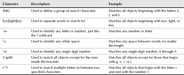
The Select ![]() Find Using Regular Expressions option provides yet another way to search for specific objects. Regular expressions are commonly used in various scripting languages and require specific syntax in order to locate objects. Table 6.5 lists some common regular expression characters.
Find Using Regular Expressions option provides yet another way to search for specific objects. Regular expressions are commonly used in various scripting languages and require specific syntax in order to locate objects. Table 6.5 lists some common regular expression characters.
TABLE 6.5 Common Regular Expression Syntax
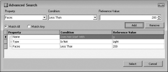
If regular expressions seem confusing, you also can search using the Advanced Search dialog box, shown in Figure 6.20. This dialog box is opened using the Select ![]() Search or by clicking the Configure Advanced Filter button. In the Property field, you can search by Name, Type, Color, Faces, or any of the other available columns. In the Condition, the options include Starts With, Does Not Start With, Contains String, Does Not Contain String, Regular Expression Matches, and Inverse Regular Expression Matches. Multiple criteria can be added to the search list.
Search or by clicking the Configure Advanced Filter button. In the Property field, you can search by Name, Type, Color, Faces, or any of the other available columns. In the Condition, the options include Starts With, Does Not Start With, Contains String, Does Not Contain String, Regular Expression Matches, and Inverse Regular Expression Matches. Multiple criteria can be added to the search list.
Editing in the Scene Explorer
Any of the display properties listed in the Scene Explorer can be enabled by simply clicking the check box to enable the property. If multiple objects are selected when a property is enabled or disabled, the same property is enabled or disabled for all the selected objects at the same time.
Note
If the Lock Cell Editing button is enabled, none of the properties can be changed.
If you click the column name, you can sort all the listed objects either in descending or ascending order. Click the column name once to sort in ascending order and again to sort in descending order. You also can right-click and select the sorting order from the pop-up menu. For example, if you click the Faces column, all the objects are sorted so the objects with the smallest number of faces are listed at the top of the interface and the objects with the most faces are listed at the bottom.
FIGURE 6.20 The Advanced Search dialog box lets you select search criteria using drop-down lists.
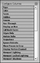
You also can rearrange the columns by dragging and dropping them to a new location. Selecting the Customize ![]() Configure Columns menu opens the Configure Columns dialog box, shown in Figure 6.21. This dialog box lists all the available remaining display property columns. To add one to the Scene Explorer, simply select it from the Configure Columns dialog box and drop it where you want it.
Configure Columns menu opens the Configure Columns dialog box, shown in Figure 6.21. This dialog box lists all the available remaining display property columns. To add one to the Scene Explorer, simply select it from the Configure Columns dialog box and drop it where you want it.
The Configure Columns dialog box includes a large number of properties that can be added as columns to the Scene Explorer including Revit Category, Revit Family, Revit Level, Revit Type, and Application Origin.
Tip
The width of each column can be altered by dragging on either side. To reset all column widths, right-click a column name and choose Best Fit (all columns) from the pop-up menu.
FIGURE 6.21 The Configure Columns dialog box holds all the display properties not currently available in the Scene Explorer.
Using the Edit menu, you also can cut, copy, and paste selected objects, called nodes. Pasting objects opens the Clone Options dialog box. The Customize menu also includes options to hide various toolbars and a choice to lay out the window using horizontal or vertical icons.
Summary
Selecting objects enables you to work with them, and Max includes many different ways to select objects. In this chapter, you've done the following:
- Learned how to use selection filters
- Selected objects with the Edit menu by Name, Layer, Color, and Region
- Selected multiple objects and used a named selection set to find the set easily
- Selected objects using other interfaces
- Accessed the Object Properties dialog box to set Display and Rendering settings for an object
- Learned how to hide and freeze objects
- Separated objects using layers
- Used the Scene Explorer dialog box
Now that you've learned how to select objects, you're ready to move them about using the transform tools, which are covered in the next chapter.