
CHAPTER 28
Working with Solids and Body Objects
Importing CAD objects
Converting Max objects to Body objects
Working with Body objects
Exporting Body objects
Okay, here's a trick for you. Take a Max primitive object, and place it completely inside another Max primitive object, such as a cube inside a larger cube. Then use the ProBoolean feature to subtract the inner cube from the outer cube. The result is nothing. That's because Max objects deal with surfaces, and if the surfaces don't overlap, then no operation is performed.
The CAD world, on the other hand, deals with volumes, also known as solids, and such an operation is common. Because much of Autodesk's efforts are directed toward the CAD and architectural markets, working with volumes becomes important. It also provides a way to bridge the CAD and Max worlds.
To address this issue, Max has introduced a way to work with volumes and solids, which in Max are known as Body Objects. Objects that are imported from a CAD package appear in Max as Body Objects, and you also can convert Max objects to this Body Object type and export the results to a CAD package. Max also includes a way to perform Boolean operations on Body Objects, so you can finally remove that inner cube.
Importing CAD Objects
If you've spent lots of time working in a CAD package to get your design to look just right and now you need to take it to Max to add some animation for an upcoming presentation, you start by importing your objects into Max using the ACIS SAT import file type. Max can also import WIRE files from Autodesk Alias Studio.
New Feature
The ability to import WIRE files in new to 3ds Max 2012.
During the import, you get a SAT Import dialog box, as shown in Figure 28.1, full of options for the import. The Standard - No Welding option is the default and should be used in most cases. It imports all objects as separate objects, allowing you to select them independently.
FIGURE 28.1 The SAT Import dialog box includes options for importing CAD objects.
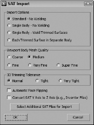
The Single Body options let you import all objects together as a single object in Max. If all objects are not welded together, you can select and move them independently in Element subobject mode. If they are welded, they act as a single object. This may be desirable if you are loading in a background or some terrain data. The final option imports each trimmed surface as a separate body object.
The Viewport Body Mesh Quality setting is used to set the density of the mesh displayed in the viewport. The 3D Trimming Tolerance option lets you set how accurately the imported objects are trimmed. It is best to start with a lower tolerance and increase it as you see import problems such as missing faces.
Caution
SAT files can be large, and selecting any of the Fine settings results in huge Max files.
Enabling the Automatic Face Flipping option causes the importer to attempt to correct any normals that are pointing the wrong way. Most CAD formats have a different coordinate system with the Z axis pointing up instead of the Y axis. Enabling the Convert SAT Y Axis to Z Axis option fixes this for the imported objects.
The Select Additional SAT Files for Import button opens a file dialog box where you can select more files to import using the current settings. Importing SAT files takes a long time, so selecting and importing several files at once is a good idea.
Converting Max Objects to Body Objects
Objects that are imported from the SAT or WIRE formats appear in Max as Body Object types in the Modify panel. Max objects can be converted to the Body Object type using the Body Object button found in the Create panel by opening the Body Objects subcategory. Simply select the object to convert, and press the Body Object button.
The conversion works best when used on only the most basic primitive objects. If a more complex mesh object needs to be converted, try converting it to a NURBS object first and then to a Body Object.
Note
Max objects that are converted into Body Objects are still only shells and not solids.
If you have multiple objects that you want to convert to Body Objects, you can use the Body Utility button, also found in the Create panel. This button is also useful for changing the properties of multiple Body Objects at once.
Working with Body Objects
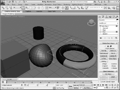
If you open a Body Object in the Modify panel, you can work with three subobjects: Edge, Face, and Element. Within the Modifier Stack is another subobject mode, Operand, which lets you work with the pieces resulting from a Boolean operation.
The notion of subobjects is unique to Body Objects. For example, the face subobject selected in Figure 28.2 wraps most of the way around the torus object. This is common for CAD object faces. You'll also notice, when subobjects are selected, that the transform tools are disabled.
FIGURE 28.2 The subobjects for Body Objects are unique from other modeling types.
Editing Body Objects
Body Object edges are different from polygon edges in that they typically only show the profile of the object. When one Body Object is cut into another, an open edge is created. Open edges are not welded to the surface and are colored blue. Open edges also mark the borders where holes in the object are located. Edges are welded to the surface using the Weld Selected or the Weld All buttons. There is also a Welding button that opens a rollout with options for selecting and welding specific edges. Welded edges are displayed as white, and selected edges are red.
The opposite of welding edges and combining faces is to explode them apart. There are buttons for exploding the selected face or exploding all faces together. The Face Flip button provides a way to switch the normal for the surface using the Face Flipping/Visibility rollout.
Applying modifiers to Body Objects
One of the benefits that Max has over CAD packages is its lengthy list of modifiers. These modifiers can alter objects quickly without changing the parametric nature of the object, but not all modifiers preserve the default object type.
Using Boolean operations with Body Objects
Within the Object Parameters rollout is a Pick Object button. Using this button, you can select other Body Objects that are outside the current selection and then use the other buttons below the Pick Object button to define how the two objects are combined. The options include the following:
- Attach: Combines the other object as an element to the selected object and welds it edges.
- Detach: Removes the selected subobject from the current object and saves it as its own Body Object. Edges also are not welded.
- Merge: Combines the other object with the current selection, making one element.
- Project: Projects the curve of a single face onto the other object along the face's normal, creating new edges.
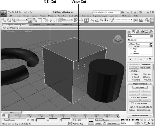
- 3-D Cut: Creates new edges on the current object by tracing the overlapping volume of the picked object.
- View Cut: Cuts into the current Body Object using a projected profile from the picked object. If the Cut Selected Only option is enabled, then the cut affects only the selected subobject.
Figure 28.3 shows a cube Body Object that has been cut using the 3-D Cut and View Cut methods. For the 3-D Cut option, the torus object was used and then moved to reveal the remaining circle where the torus overlapped the cube. The View Cut option projected the edges from the cylinder onto the cube.
Using the Join Bodies and Body Cutter features
If two or more objects are selected, you can use the Join Bodies button found in the Body Objects subcategory of the Create panel to convert the objects into Body Objects and combine them. Within the Conversion Parameters rollout, you can select how the objects are combined. The options including weld only the edges, weld into solid, weld edges to surfaces, do nothing, intersect + merge faces, and Boolean union.
FIGURE 28.3 Body Objects can be cut using the 3-D Cut or View Cut operations.
Note
The Join Bodies button doesn't require that one of the objects is already a Body Object.
The resulting object is a Join Bodies object type that allows you to revisit the Operands as subobjects and in the Operator Parameters rollout. If you're happy with the result, you can use the Body Objects button in the Create panel to convert the resulting object into a Body Object.
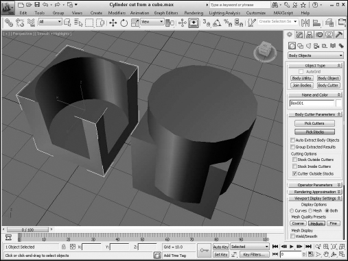
The Body Cutter works like the ProCutter tool and lets you cut away part of an overlapping volume. This begins by selecting an object; it doesn't need to be a Body Object. Then click the Body Cutter button in the Create panel. This creates a Body Cutter object and presents several rollouts of options. The Body Cutter object is a cutter, and you can choose the Pick Stocks button in the Body Cutter Parameters rollout to select the base object. You also can choose additional cutter objects with the Pick Cutters button.
Once cut, you can select which portion to display with the Cutting Options. The options include Stock Outside Cutters, Stock Inside Cutters, and Cutter Outside Stocks. Figure 28.4 shows a cylinder cut from a cube object.
FIGURE 28.4 The Body Cutter feature works like the ProCutter tool.
Setting display and rendering properties
Although Body Objects display and work in the Max world, you have control over how refined the objects are when being displayed in the viewport and when rendered. The Rendering Approximation rollout lets you define how the Body Object is treated when rendered. The simple method is to use the Draft, Good, and Production presets depending on how much time you have to wait for the rendering to finish. For each, you can get more specific in defining how the face, edges, and chords are approximated.
Many of the same values, along with three quality settings, also are available in the Viewport Display Settings rollout. These affect how the object appears within the viewports.
Exporting Body Objects
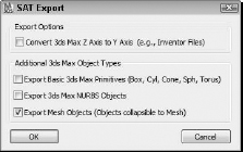
If you want to move the Body Objects back to a CAD package, you can use the File ![]() Export menu and choose the ASIC format. This opens the SAT Export dialog box, shown in Figure 28.5. When exporting, you have the option of switching back to the standard CAD axis with the Z axis as up. You also need to specify the type of object being exported. It could be a simple primitive, a NURBS object, or a Mesh object.
Export menu and choose the ASIC format. This opens the SAT Export dialog box, shown in Figure 28.5. When exporting, you have the option of switching back to the standard CAD axis with the Z axis as up. You also need to specify the type of object being exported. It could be a simple primitive, a NURBS object, or a Mesh object.
If you are exporting an object that has modifiers applied to it, you want to use the Export Mesh Objects option and be aware that the stack will be collapsed during the export.
FIGURE 28.5 The SAT Export dialog box lets you specify what type of object is being exported.
Summary
Body Objects provide a critical bridge between CAD objects and Max. Body Objects can be imported using the SAT format or Max objects can be converted to the Body Object type. Body Objects can be combined using several Boolean features and can be exported back to the CAD package. This chapter covered the following topics:
- Importing CAD objects
- Converting Max objects to Body Objects
- Applying modifiers to Body Objects
- Using the Join Bodies and Body Cutter tools
- Exporting Body Objects
The next chapter is really hairy. In fact, it is all about adding hair, fur, and cloth to your models.