
CHAPTER 22
Animating with Constraints and Simple Controllers
Using constraints
Attaching an object to the surface of an object
Making an object travel along a path with the Path constraint
Controlling the weighted position and orientation of objects
Shifting between two controlling objects using the Link constraint
Following objects with the LookAt constraint
Understanding the controller types
Assigning controllers using the Motion panel and the Track View
Setting default controllers
When you first begin animating and working with keys, having Max figure out all the frames between the start and end keys seems amazing, especially if you've ever animated in 2D by drawing every frame. But soon you realize that animating with keys can be time-consuming for complex realistic motions, and again, Max comes to the rescue. You can use animation constraints and controllers to automate the creation of keys for certain types of motions.
Constraints and controllers store and manage the key values for all animations in Max. When you animate an object using the Auto Key button, the default controller is automatically assigned. You can change the assigned controller or alter its parameters using the Motion panel or the Track View.
This chapter explains how to work with constraints and some simple controllers. For example, you can use the Noise controller to add random motion to a flag blowing in the wind or use the Surface constraint to keep a bumper car moving over the surface.
Restricting Movement with Constraints
The trick of animating an object is to make it go where you want it to go. Animating objects deals not only with controlling the motion of the object but also with controlling its lack of motion. Constraints are a type of animation controller that you can use to restrict the motion of an object.
Using these constraints, you can force objects to stay attached to another object or follow a path. For example, the Attachment constraint can be used to make a robot's feet stay connected to a ground plane as it moves. The purpose of these constraints is to make animating your objects easier.
Using constraints
You can apply constraints to selected objects using the Animation ![]() Constraints menu. The constraints contained within this menu include Attachment, Surface, Path, Position, Link, LookAt, and Orientation.
Constraints menu. The constraints contained within this menu include Attachment, Surface, Path, Position, Link, LookAt, and Orientation.
![]() All constraints have the same controller icon displayed in the Motion panel or the Track View.
All constraints have the same controller icon displayed in the Motion panel or the Track View.
After you select one of the constraints from the Animation ![]() Constraints menu, a dotted link line extends from the current selected object to the mouse cursor. You can select a target object in any of the viewports to apply the constraint. The cursor changes to a plus sign when it is over a target object that can be selected. Selecting a constraint from the Constraints menu also opens the Motion panel, where the settings of the constraint can be modified.
Constraints menu, a dotted link line extends from the current selected object to the mouse cursor. You can select a target object in any of the viewports to apply the constraint. The cursor changes to a plus sign when it is over a target object that can be selected. Selecting a constraint from the Constraints menu also opens the Motion panel, where the settings of the constraint can be modified.
![]() You also can apply constraints using the Assign Controller button found in the Motion panel and in the Track View window.
You also can apply constraints using the Assign Controller button found in the Motion panel and in the Track View window.
Cross-Reference
Find out more about the Track View window in Chapter 37, “Working with the F-Curve Editor in the Track View.”
Working with the constraints
Each constraint is slightly different, but learning how to use these constraints will help you control the animated objects within a scene. You can apply several constraints to a single object. All constraints that are applied to an object are displayed in a list found in the Motion panel. From this list, you can select which constraint to make active and which to delete. You also can cut and paste constraints between objects.
Attachment constraint
The Attachment constraint determines an object's position by attaching it to the face of another object. This constraint lets you attach an object to the surface of another object. For example, you could animate the launch of a rocket ship with booster rockets that are attached with the Attachment constraint. The booster rockets would move along with the ship until the time when they are jettisoned.
The pivot point of the object that the constraint is applied to is attached to the target object. At the top of the Attachment Parameters rollout is a Pick Object button for selecting the target object to attach to. You can use this button to change the target object or to select the target object if the Animation ![]() Constraints menu wasn't used. There is also an option to align the object to the surface. The Update section enables you to manually or automatically update the attachment values.
Constraints menu wasn't used. There is also an option to align the object to the surface. The Update section enables you to manually or automatically update the attachment values.
Note
The Attachment constraint shows up in the Position track of the Assign Controller rollout as the Position List controller. To minimize the effect of other controllers, set their Weight values in the Position List rollout to 0.
The Key Info section of the Attachment Parameters rollout displays the key number and lets you move between the various keys. The Time value is the current key value. In the Face field, you can specify the exact number of the face to attach to. To set this face, click the Set Position button and drag over the target object. The A and B values represent Barycentric coordinates for defining how the object lies on the face. You can change these coordinate values by entering values or by dragging the red cross-hairs in the box below the A and B values. The easiest way to position an object is to use the Set Position button to place the object and then to enhance its position with the A and B values. The Set Position button stays active until you click it again.
The TCB section sets the Tension, Continuity, and Bias values for the constraint. You also can set the Ease To and Ease From values.
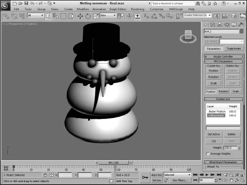
Tutorial: Attaching eyes to a melting snowman
When part of a model is deformed, such as applying the Melt modifier to a snowman's body, smaller parts like the eyes either get left behind or get the full weight of the modifier applied to them. If the Melt modifier weren't applied to these items, they would stay floating in the air while the rest of the snowman melted about them. This problem can be fixed with the Attachment constraint, which causes the eyes to remain attached to the snowball as it melts.
Cross-Reference
The tutorial where the Melt modifier is applied to the snowman is included in Chapter 35, “Using Animation Layers, Modifiers, and Complex Controllers.”
To constrain the solid objects to a melting snowman, follow these steps:
- Open the Melting snowman.max file from the Chap 22 directory on the CD.
This file includes the melting snowman file from the previous chapter with the Melt modifier applied to all objects.
- Select the left eye object in the scene. In the Modifier Stack, select the Melt modifier and click the Remove Modifier button to throw that modifier away.
- With the left eye still selected, select Animation
 Constraints Attachment Constraint. A connecting line appears in the active viewport. Click the top snowball to select it as the attachment object. This moves the eye object to the top of the snowball where the snowball's first face is located.
 - In the Attachment Parameters rollout, change the Face value until the eye is positioned where it should be. This should be around face 315. Then change the A and B values (or drag in the Position graph) to position the eye where it looks good.
- Repeat Step 5 for the right eye and for any other objects in the scene that you want to attach.
- Click the Play button (/) and notice that the snow melts, but the eye objects stay the same size.
Figure 22.1 shows the resulting melted snowman.
Surface constraint
The Surface constraint moves an object so that it is on the surface of another object. The object with Surface constraint applied to it is positioned so that its pivot point is on the surface of the target object. You can use this constraint only on certain objects, including Spheres, Cones, Cylinders, Toruses, Quad Patches, Loft objects, and NURBS objects.
FIGURE 22.1 The Attachment constraint sticks one object to the surface of another.
Caution
Because the Surface Constraint works using the parametric nature of the attached surface, only certain object types can be used with the surface constraint, including primitive objects like a sphere, cone, cylinder, patch, and NURBS objects.
In the Surface Controller Parameters rollout is the name of the target object that was selected after the menu command. The Pick Surface button enables you to select a different surface to attach to. You also can select specific U and V Position values. Alignment options include No Alignment, Align to U, Align to V, and a Flip toggle.
Note
Don't be confused because the rollout is named Surface Controller Parameters instead of Surface Constraint Parameters. The developers at Autodesk must have missed this one.
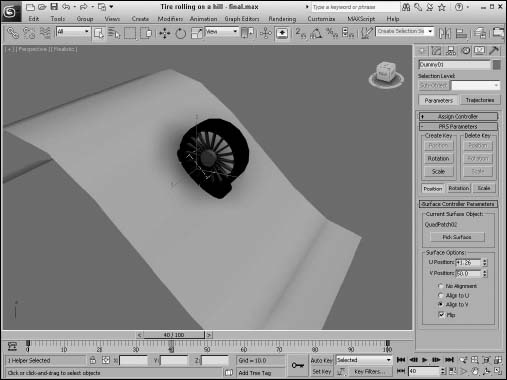
Tutorial: Rolling a tire down a hill with the Surface constraint
Moving a vehicle across a landscape can be a difficult procedure if you need to place every rotation and position key, but with the Surface constraint, it becomes easy. In this tutorial, you use the Surface constraint to roll a tire down a hill.
To roll a tire down a hill with the Surface constraint, follow these steps:
- Open the Tire rolling on a hill.max file from the Chap 22 directory on the CD.
This file includes a patch grid hill and a wheel object made from primitives.
- Create a dummy object from the Helpers category, and link the tire object to it as a child. This causes the tire to move along with the dummy object. Position the dummy object's pivot point at the bottom of the tire and the top of the hill. The pivot point can be moved using the Affect Pivot Only button in the Hierarchy panel.
- Select the dummy object, choose Animation Constraints Surface Constraint, and select the hill object.
- In the Surface Controller Parameters rollout, select the Align to V and Flip options to position the dummy and tire objects at the top of the hill. Set the V Position value to 50 to move the tire down the hill.
- Click the Auto Key button (or press the N key), drag the Time Slider to frame 100, and change the U Position to 100. Click the Animate button again to deactivate it, and click the Play Animation button to see the tire move down the hill.
Figure 22.2 shows the tire as it moves down the hill. In the Top view, you can see the function curves for this motion.
FIGURE 22.2 The Surface constraint can animate one object moving across the surface of another.
Path constraint
The Path constraint lets you select a spline path for the object to follow. The object is locked to the path and follows it even if the spline is changed. This is one of the most useful constraints because you can control the exact motion of an object using a spline. With Max's spline features, you can control very precisely the motions of objects that are constrained with the Path constraint. A good example of this constraint is an animated train following a track. Using a spline to create the train tracks, you can easily animate the train using the Path constraint.
When you choose the Animation ![]() Constraints
Constraints ![]() Path Constraint menu command, you can select a single path for the object to follow. This path is added to a list of paths in the Path Parameters rollout.
Path Constraint menu command, you can select a single path for the object to follow. This path is added to a list of paths in the Path Parameters rollout.
The Path Parameters rollout also includes Add and Delete Path buttons for adding and deleting paths to and from the list. If two paths are added to the list, then the object follows the position centered between these two paths. By adjusting the Weight value for each path, you can make the object favor a specific path.
The Path Options include a % Along Path value for defining the object's position along the path. This value ranges from 0 at one end to 100 at the other end. The Follow option causes the object to be aligned with the path as it moves, and the Bank option causes the object to rotate to simulate a banking motion.
The Bank Amount value sets the depth of the bank, and the Smoothness value determines how smooth the bank is. The Allow Upside Down option lets the object spin completely about the axis, and the Constant Velocity option keeps the speed regular. The Loop option returns the object to its original position for the last frame of the animation, setting up a looping animation sequence. The Relative option lets the object maintain its current position and does not move the object to the start of the path. From its original position, it follows the path from its relative position. At the bottom of the Path Parameters rollout, you can select the axis to use.
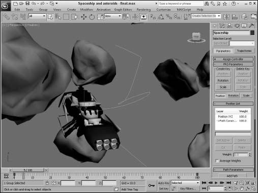
Tutorial: Creating a spaceship flight path
Another way to use splines is to create animation paths. As an example, you use a Line spline to create an animation path. You can use splines for animation paths in two ways. One way is to create a spline and have an object follow it using either the Path constraint or the Path Follow Space Warp. The first vertex of the spline marks the first frame of the animation. The other way is to animate an object and then edit the Trajectory path.
In this tutorial, you use a simple path and attach it to a spaceship model. Viewpoint Datalabs provided the spaceship model.
To attach an object to a spline path, follow these steps:
- Open the Spaceship and asteroids.max file from the Chap 22 directory on the CD.
This file contains the spaceship model and several asteroid objects.
- Select Create Shapes Line, and click and drag in the Top viewport to create an animation path that moves the spaceship through the asteroids. Right-click when the path is complete. Then select the Modify panel, click the Vertex button in the Selection rollout to enable Vertex subobject mode, and edit several vertices in the Front viewport. Then right-click to exit vertex subobject mode.
- With the spaceship selected, choose Animation Constraints Path Constraint. Then click the animation path to select it as the path to follow. Select the Follow option in the Path Parameters rollout, and choose the Y-Axis option.
- Click the Play Animation button in the Time Controls to see the spaceship follow the path.
Figure 22.3 shows the spaceship as it moves between the asteroids.
FIGURE 22.3 The spaceship object has been attached to a spline path that it follows.
Position constraint
You can use the Position constraint to tie the position of an object to the weighted position of several target objects. For example, you could animate a formation of fighter jets by animating one of the jets and using Position constraints on all adjacent jets.
The Position constraint menu option lets you select a single target object, enabling you to place the pivot points of the two objects on top of one another. To add another target object, click the Add Position Target button in the Position Constraint rollout in the Motion panel. This button enables you to select another target object in the viewports; the target name appears within the target list in the rollout.
If you select a target name in the target list, you can assign a weight to the target. The constrained object is positioned close to the object with the higher weighted value. The Weight value provides a way to center objects between several other objects. The Keep Initial Offset option lets the object stay in its current location, but centers it relative to this position.
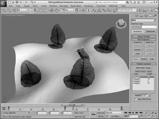
Figure 22.4 shows a sled positioned between four tree objects using the Position constraint. Notice how the weight of the downhill tree object is weighted higher than the other targets and the sled is close to it.
FIGURE 22.4 You can use the Position constraint to control the position of an object in relation to its targets.
Link constraint
The Link constraint can transfer hierarchical links between objects. This constraint can cause a child's link to be switched during an animation. Any time you animate a complex model with a dummy object, the Link constraint makes it possible to switch control from one dummy object to another during the animation sequence. This keeps the motions of the dummy objects simple.
The Link Params rollout includes Add Link and Delete Link buttons, a list of linked objects, and the Start Time field. To switch the link of an object, enter for the Start Time the frame where you want the link to switch, or drag the Time Slider and click the Add Link button. Then select the new parent object. The Delete key becomes active when you select a link in the list.
If you create a link using the Link constraint, the object is not recognized as a child in any hierarchies.
All links are kept in a list in the Link Params rollout. You can add links to this list with the Add Link button, create a link to the world with the Link to World button, or delete links with the Delete Link button. The Start Time field specifies when the selected object takes control of the link. The object listed in the list is the parent object, so the Start Time setting determines when each parent object takes control.
The Key Mode section lets you choose a No Key option. This option does not write any keyframes for the object. If you want to set keys, you can choose the Key Nodes options and set keys for the object itself (Child option) or for the entire hierarchy (Parent option). The Key Entire Hierarchy sets keys for the object and its parents (Child option) or for the object and its targets and their hierarchies (Parent option).
This constraint also includes the PRS Parameters and Key Info rollouts.
Caution
You cannot use Link constraints with Inverse Kinematics systems.
Tutorial: Skating a figure eight
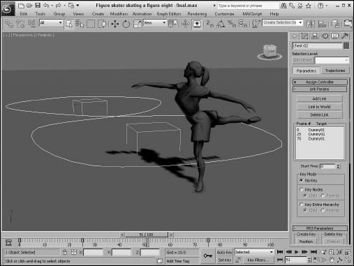
For an animated object to switch its link from one parent to another halfway through an animation, you need to use the Link constraint. Rotating an object about a static point is easy enough: Simply link the object to a dummy object, and rotate the dummy object. The figure-eight motion is more complex, but you can do it with the Link constraint.
To move an object in a figure eight, follow these steps:
- Open the Figure skater skating a figure eight.max file from the Chap 22 directory on the CD.
This file includes a figure skater model imported from Poser and two dummy objects. The figure skater is linked to the first dummy object (the one initially closest to the skater).
- Click the Auto Key button (or press the N key), drag the Time Slider to frame 100, and rotate the first dummy object two full revolutions in the Top viewport.
- Select the second dummy object, and rotate it two full revolutions in the opposite direction. Click the Auto Key button again to deactivate it.
Tip
If you enable the Angle Snap Toggle button on the main toolbar, then it is easier to rotate objects exactly two revolutions.
- With the figure skater selected, choose Animation Constraints Link Constraint. Then click the first dummy object (the top one in the Top viewport).
The Link constraint is assigned to the figure skater.
- In the Link Params rollout, click the Add Link button. With the first dummy object selected in the viewport, set the Start Time value to 0. Then click the second dummy object, and set the Start Time to 25 in the Link Params rollout. Finally, click the first dummy object again, and set the Start Time to 75.
- Click the Play Animation button (or press the / key) to see the animation play.
Another way to accomplish this same motion is to create a spline of a figure eight and use the Path constraint.
Figure 22.5 shows the skater as she makes her path around the two dummy objects.
FIGURE 22.5 With the Link constraint, the figure skater can move in a figure eight by rotating about two dummy objects.
LookAt constraint
The LookAt constraint won't move an object, but it rotates the object so it is always orientated toward the target object. For example, you could use the LookAt constraint to animate a character's head that is watching a flying bumblebee. It is also very useful to apply to camera objects that follow a specific object throughout the animation.
After you select a target object, a single line extends from the object and points at the target object. This line, called the Viewline, is visible only within the viewports.
The LookAt Constraint rollout, like many of the other constraints, includes a list of targets. With the Add and Delete LookAt Target buttons, you can add and remove targets from the list. If several targets are on the list, the object is centered on a location between them. Using the Weight value, you can cause the various targets to have more of an influence over the orientation of the object. The Keep Initial Offset option prevents the object from reorienting itself when the constraint is applied. Any movement is relative to its original position.
You can set the Viewline length, which is the distance that the Viewline extends from the object. The Viewline Length Absolute option draws the Viewline from the object to its target, ignoring the length value.
The Set Orientation button lets you change the offset orientation of the object using the Select and Rotation button on the main toolbar. If you get lost, the Reset Orientation button returns the orientation to its original position. You can select which local axis points at the target object.
The Upnode is an object that defines the up direction. If the LookAt axis ever lines up with the Upnode axis, then the object flips upside-down. To prevent this, you can select which local axis is used as the LookAt axis and which axis points at the Upnode. The World is the default Upnode object, but you can select any object as the Upnode object by deselecting the World object and clicking the button to its right.
To control the Upnode, you can select the LookAt option or the Axis Alignment option, which enables the Align to Upnode Axis option. Using this option, you can specify which axis points toward the Upnode.
Caution
The object using the LookAt constraint flips when the target point is positioned directly above or below the object's pivot point.
When you assign the LookAt constraint, the Create Key button for rotation changes to Roll. This is because the camera is locked to point at the assigned object and cannot rotate; rather, it can only roll about the axis.
You can use the LookAt constraint to let cameras follow objects as they move around a scene. It is the default transform controller for Target camera objects.
Orientation constraint
You can use the Orientation constraint to lock the rotation of an object to another object. You can move and scale the objects independently, but the constrained object rotates along with the target object. A good example of an animation that uses this type of constraint is a satellite that orbits the Earth. You can offset the satellite and still constrain it to the Earth's surface. Then, as the Earth moves, the satellite follows.
In the Orientation Constraint rollout, you can select several orientation targets and weight them in the same manner as with the Position constraint. The target with the greatest weight value has the most influence over the object's orientation. You also can constrain an object to the World object. The Keep Initial Offset option maintains the object's original orientation and rotates it relative to this original orientation. The Transform Rule setting determines whether the object rotates using the Local or World Coordinate Systems.
Using the Walkthrough Assistant
One alternative to using the Path and LookAt constraint is to use the Walkthrough Assistant. This tool is accessed from the Animation menu. It opens up a utility panel with several rollouts, as shown in Figure 22.6. Using this panel, you can create a new camera, select a path, and set the viewport to use the created camera. You can then use the View Controls rollout to cause the view to tilt to the left or right as you move through the path. This automates the process of getting a camera to follow a path.
FIGURE 22.6 The Walkthrough Assistant automates several constraints into a single interface.
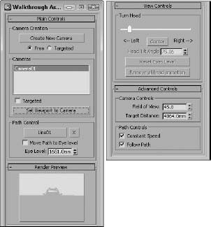
The Walkthrough Assistant also includes a Render Preview that you use to see the results. If you drag the Time Slider to a different frame and click the Render Preview pane, the preview is updated. At specific frames, you can drag the Turn Head slider to change where the camera is looking. You can even tilt the camera up and down as well as side to side.
In the Advanced Controls rollout (which appears only after a camera has been created) are options for changing the Field of View and the Target Distance, which is useful if you're using a Depth of Field effect. You also can set the camera to move at a constant speed and an option to cause the camera to follow the path.
Understanding Controller Types
Controllers are used to set the keys for animation sequences. Every object and parameter that is animated has a controller assigned, and almost every controller has parameters that you can alter to change its functionality. Some controllers present these parameters as rollouts in the Motion panel, and others use a Properties dialog box.
Max has five basic controller types that work with only a single parameter or track and one specialized controller type that manages several tracks at once (the Transform controllers). The type depends on the type of values the controller works with. The types include the following:
- Transform controllers: A special controller type that applies to all transforms (position, rotation, and scale) at the same time, such as the Position, Rotation, Scale (PRS) controllers
- Position controllers: Control the position coordinates for objects, consisting of X, Y, and Z values
- Rotation controllers: Control the rotation values for objects along all three axes
- Scale controllers: Control the scale values for objects as percentages for each axis
- Float controllers: Used for all parameters with a single numeric value, such as Wind Strength and Sphere Radius
- Point3 controllers: Consist of color components for red, green, and blue, such as Diffuse and Background colors
Note
Understanding the different controller types is important. When you copy and paste controller parameters between different tracks, both tracks must have the same controller type.
Float controllers work with parameters that use float numbers, such as a sphere's Radius or a plane object's Scale Multiplier value. Float values are numbers with a decimal value, such as 2.3 or 10.99. A Float controller is assigned to any parameter that is animated. After it is assigned, you can access the function curves and keys for this controller in the Track View and in the Track Bar. Because Float and Point3 controllers are assigned to parameters and not to objects, they don't appear in the Animation menu.
Assigning Controllers
Any object or parameter that is animated is automatically assigned a controller. The controller that is assigned is the default controller. The Animation panel in the Preference Settings dialog box lists the default controllers and lets you change them. You can change this automatic default controller using the Track View window or the transformation tracks located in the Motion panel.
Automatically assigned controllers
The default controllers are automatically assigned for an object's transformation tracks when the object is created. For example, if you create a simple sphere and then open the Motion panel (which has the icon that looks like a wheel), you can find the transformation tracks in the Assign Controller rollout. The default Position controller is Position XYZ, the default Rotation controller is Euler XYZ, and the default Scale controller is the Bézier Scale controller.
The default controller depends on the type of object. For example, the Barycentric Morph controller is automatically assigned when you create a morph compound object, and the Master Point controller is automatically assigned to any vertices or control points subobjects that are animated.
Note
Because controllers are automatically assigned to animation tracks, they cannot be removed; they can only be changed to a different controller. There is no function to delete controllers.
Assigning controllers with the Animation menu
The easiest way to assign a controller to an object is with the Animation menu. Located under the Animation menu are four controller submenus consisting of Transform, Position, Rotation, and Scale.
Note
Although constraints are contained within a separate menu, they control the animating of keys just like controllers.
When a controller is assigned to an object using the Animation menu, the existing controller is not removed, but the new controller is added as part of a list along with the other controllers. You can see all these controllers in the Motion panel.
For example, Figure 22.7 shows the Motion panel for a sphere object that has the default Position XYZ controller assigned to the Position track. If you choose Animation ![]() Position Controllers
Position Controllers ![]() Noise, then the Position List controller is added to the Position track, of which Position XYZ and Noise are two available controllers. This lets you animate multiple motions such as the shimmy of a car with a bad carburetor as it moves down the road.
Noise, then the Position List controller is added to the Position track, of which Position XYZ and Noise are two available controllers. This lets you animate multiple motions such as the shimmy of a car with a bad carburetor as it moves down the road.
FIGURE 22.7 The Motion panel displays all transform controllers applied to an object.
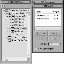
The List controller makes it possible to add several controllers to a single track. It also allows you to set Weights for each of its controllers. Using the Position List rollout, you can set the active controller and delete controllers from the list. You also can Cut and Paste controllers to other tracks.
Assigning controllers in the Motion panel
The top of the Motion panel includes two buttons: Parameters and Trajectories. Clicking the Parameters button makes the Assign Controller rollout available.
![]() To change a transformation track's controller, select the track and click the Assign Controller button positioned directly above the list. An Assign Controller dialog box opens that is specific to the track you selected.
To change a transformation track's controller, select the track and click the Assign Controller button positioned directly above the list. An Assign Controller dialog box opens that is specific to the track you selected.
Cross-Reference
For more about the Trajectories button, see Chapter 21, “Understanding Animation and Keyframes.”
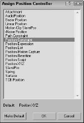
For example, Figure 22.8 shows the Assign Position Controller dialog box for selecting a controller for the Position track. The arrow mark (>) shows the current selected controller. At the bottom of the dialog box, the default controller type is listed. Select a new controller from the list, and click OK. This new controller now is listed in the track, and the controller's rollouts appear beneath the Assign Controller rollout.
FIGURE 22.8 The Assign Position Controller dialog box lets you select a controller to assign.
Note
Transformation controllers can be applied in the Motion panel, but the Track View can be used to apply controllers to all parameters including transforms.
Assigning controllers in the Track View
![]() You also can use the Track View to assign controllers. To do this, locate and select the track to apply a controller to, and then click the Assign Controller button on the Controllers toolbar, choose the Controller
You also can use the Track View to assign controllers. To do this, locate and select the track to apply a controller to, and then click the Assign Controller button on the Controllers toolbar, choose the Controller ![]() Assign (keyboard shortcut, C if the Keyboard Shortcut Override Toggle on the main toolbar is enabled) menu command, or right-click the track and select Assign Controller from the pop-up menu. An Assign Controller dialog box opens in which you can select the controller to use.
Assign (keyboard shortcut, C if the Keyboard Shortcut Override Toggle on the main toolbar is enabled) menu command, or right-click the track and select Assign Controller from the pop-up menu. An Assign Controller dialog box opens in which you can select the controller to use.
Cross-Reference
Chapter 37, “Working with the F-Curve Editor in the Track View,” covers the details of the Track View.
You also can use the Controller toolbar to copy and paste controllers between tracks, but you can paste controllers only to similar types of tracks. When you paste controllers, the Paste dialog box lets you choose to paste the controller as a copy or as an instance. Changing an instanced controller's parameters changes the parameters for all instances. The Paste dialog box also includes an option to replace all instances. This option replaces all instances of the controller, whether or not they are selected.
Setting default controllers
When you assign controllers using the Track View, the Assign Controller dialog box includes the option Make Default. With this option, the selected controller becomes the default for the selected track.
You also can set the global default controller for each type of track by choosing Customize ![]() Preferences, selecting the Animation panel, and then clicking the Set Defaults button. The Set Controller Defaults dialog box opens, in which you can set the default parameter settings, such as the In and Out curves for the controller. To set the default controller, select a controller from the list and click the Set Defaults button to open a controller–specific dialog box where you can adjust the controller parameters. The Animation panel also includes a button to revert to the original settings.
Preferences, selecting the Animation panel, and then clicking the Set Defaults button. The Set Controller Defaults dialog box opens, in which you can set the default parameter settings, such as the In and Out curves for the controller. To set the default controller, select a controller from the list and click the Set Defaults button to open a controller–specific dialog box where you can adjust the controller parameters. The Animation panel also includes a button to revert to the original settings.
Note
Changing a default controller does not change any currently assigned controllers.
Examining Some Simple Controllers
Now that you've learned how to assign controllers, let's look at some simple controllers.
Cross-Reference
Many more controllers are available. You can learn about these controllers in Chapter 35, “Using Animation Layers, Modifiers, and Complex Controllers.”
Earlier in the chapter, I mentioned six specific controller types. These types define the type of data that the controller works with. This section covers the various controllers according to the types of tracks with which they work.
Note
Looking at the function curves for a controller provides a good idea of how you can control it, so many of the figures that follow show the various function curves for the different controllers.
Each of these controllers has a unique icon to represent it in the Track View. This makes them easy to identify.
Bézier controller
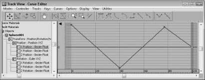
![]() The Bézier controller is the default controller for many parameters. It enables you to interpolate between values using an adjustable Bézier spline. By dragging its tangent vertex handles, you can control the spline's curvature. Tangent handles produce a smooth transition when they lie on the same line, or you can create an angle between them for a sharp point. Figure 22.9 shows the Bézier controller assigned to a Position track.
The Bézier controller is the default controller for many parameters. It enables you to interpolate between values using an adjustable Bézier spline. By dragging its tangent vertex handles, you can control the spline's curvature. Tangent handles produce a smooth transition when they lie on the same line, or you can create an angle between them for a sharp point. Figure 22.9 shows the Bézier controller assigned to a Position track.
The Bézier controller parameters are displayed in the Motion panel under two rollouts: Key Info (Basic) and Key Info (Advanced).
At the top of the Key Info (Basic) rollout are two arrows and a field that shows the key number. The arrows let you move between the Previous and Next keys. Each vertex shown in the function curve represents a key. The Time field displays the frame number where the key is located. The Time Lock button next to the Time field can be set to prevent the key from being dragged in Track View. The value fields show the values for the selected track; the number of fields changes depending on the type of track that is selected.
FIGURE 22.9 The Bézier controller produces smooth animation curves.

At the bottom of the Key Info (Basic) rollout are two flyout buttons for specifying the In and Out curves for the key. The arrows to the sides of these buttons move between the various In/Out curve types. The curve types include Smooth, Linear, Step, Slow, Fast, Custom, and Tangent Copy.
Cross-Reference
Chapter 37, “Working with the F-Curve Editor in the Track View,” describes these various In/Out curve types.
The In and Out values in the Key Info (Advanced) rollout are enabled only when the Custom curve type is selected. These fields let you define the rate applied to each axis of the curve. The Lock button changes the two values by equal and opposite amounts. The Normalize Time button averages the positions of all keys. The Constant Velocity option interpolates the key between its neighboring keys to provide smoother motion.
Linear controller
![]() The Linear controller interpolates between two values to create a straight line by changing its value at a constant rate over time.
The Linear controller interpolates between two values to create a straight line by changing its value at a constant rate over time.
The Linear controller doesn't include any parameters and can be applied to time or values. Figure 22.10 shows the curves from the previous example after the Linear controller is assigned—all curves have been replaced with straight lines.
FIGURE 22.10 The Linear controller uses straight lines.
Noise controller
![]() The Noise controller applies random variations in a track's values. In the Noise Controller dialog box, shown in Figure 22.11, the Seed value determines the randomness of the noise and the Frequency value determines how jagged the noise is. You also can set the Strength along each axis: The > (greater than) 0 option for each axis makes the noise values remain positive.
The Noise controller applies random variations in a track's values. In the Noise Controller dialog box, shown in Figure 22.11, the Seed value determines the randomness of the noise and the Frequency value determines how jagged the noise is. You also can set the Strength along each axis: The > (greater than) 0 option for each axis makes the noise values remain positive.
FIGURE 22.11 The Noise controller properties let you set the noise strength for each axis.
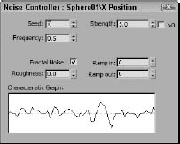
You also have an option to enable Fractal Noise with a Roughness setting.
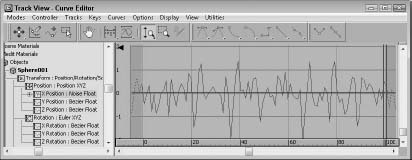
The Ramp in and Ramp out values determine the length of time before or until the noise can reach full value. The Characteristic Graph gives a visual look at the noise over the range. Figure 22.12 shows the Noise controller assigned to the Position track. If you need to change any Noise properties, right-click the Noise track and select Properties from the pop-up menu.
FIGURE 22.12 The Noise controller lets you randomly alter track values.
Spring controller
![]() The Spring controller is similar in many ways to the Flex modifier in that it adds secondary motion associated with the wiggle of a spring after a force has been applied and then removed. When the Spring controller is applied, a panel with two rollouts appears. These rollouts, shown in Figure 22.13, let you control the physical properties of the spring and the forces that influence it.
The Spring controller is similar in many ways to the Flex modifier in that it adds secondary motion associated with the wiggle of a spring after a force has been applied and then removed. When the Spring controller is applied, a panel with two rollouts appears. These rollouts, shown in Figure 22.13, let you control the physical properties of the spring and the forces that influence it.
FIGURE 22.13 The Spring controller rollouts can add additional springs and forces.
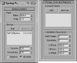
In the Spring Dynamics rollout, you can change the Mass and Drag values. Higher mass values result in greater secondary motion as the object is moved, and the Drag value controls how quickly the bouncing motion stops. You can add multiple springs, each with its own Tension and Damping values to be applied Relative or Absolute.
The Forces, Limits, and Precision rollout lets you add forces that affect the spring motion. The Add button lets you identify these forces, which are typically Space Warps, and you can limit the effect to specific axes.
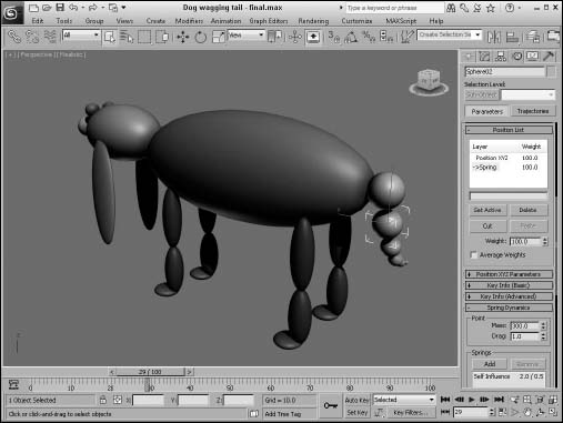
Tutorial: Wagging a tail with the Spring controller
One of the best uses of the Spring controller is to gain the secondary motion associated with an existing motion. For example, if a character moves, then an appendage such as a tail can easily follow if you apply a Spring controller to it.
To wag a row of spheres using the Spring controller, follow these steps:
- Open the Dog wagging tail.max file from the Chap 22 directory on the CD.
This file contains a linked row of spheres with the head sphere animated rotating back and forth.
- Select the smallest sphere, and choose the Animation Position Controllers Spring menu command. This moves the sphere to its parent. Choose the Select and Move button (or press the W key), and return the sphere to its original position.
- Repeat Step 2 for the remaining spheres, moving from smallest to largest.
- Click the Play Animation button (or press the / key) to see the resulting motion.
Figure 22.14 shows a frame of the final motion. Notice that the spheres aren't lined up exactly. The smallest sphere is moving the greatest distance because all the springs are adding their effect.
FIGURE 22.14 The Spring controller adds secondary motion to the existing motion of the largest sphere.
Position XYZ controller
![]() The Position XYZ controller splits position transforms into three separate tracks, one for each axis. Each axis has a Bézier controller applied to it, but each component track can be assigned a different controller. The Position XYZ Parameters rollout lets you switch between the component axes.
The Position XYZ controller splits position transforms into three separate tracks, one for each axis. Each axis has a Bézier controller applied to it, but each component track can be assigned a different controller. The Position XYZ Parameters rollout lets you switch between the component axes.
The Rotation tracks use a variety of controllers, many of them common to the Position track. This section lists the controllers that can be used only with the Rotation track.
Scale XYZ controller
![]() Max has one controller that you can use only in Scale tracks. The Scale XYZ controller breaks scale transforms into three separate tracks, one for each axis. This feature enables you to precisely control the scaling of an object along separate axes. It is a better alternative to using Select and Non-Uniform Scale from the main toolbar because it is independent of the object geometry.
Max has one controller that you can use only in Scale tracks. The Scale XYZ controller breaks scale transforms into three separate tracks, one for each axis. This feature enables you to precisely control the scaling of an object along separate axes. It is a better alternative to using Select and Non-Uniform Scale from the main toolbar because it is independent of the object geometry.
The Scale XYZ Parameters rollout lets you select which axis to work with. This controller works the same way as the other position and rotation XYZ controllers.
Summary
Using the Animation ![]() Constraints menu, you can apply constraints to objects. This menu also lets you select a target object. You can use the various constraints to limit the motion of objects, which is helpful as you begin to animate. If you're an animator, you should thank your lucky stars for controllers. Controllers offer power flexibility for animating objects—and just think of all those keys that you don't have to set by hand.
Constraints menu, you can apply constraints to objects. This menu also lets you select a target object. You can use the various constraints to limit the motion of objects, which is helpful as you begin to animate. If you're an animator, you should thank your lucky stars for controllers. Controllers offer power flexibility for animating objects—and just think of all those keys that you don't have to set by hand.
This chapter covered the basics of using the Expression controller. Using mathematical formulas to control the animation of an object's transformation and parameters offers lots of power. You also can use the values of one object to control another object.
In this chapter, you accomplished the following:
- Constrained an object to the surface of another object using the Attachment and Surface constraints
- Forced an object to travel along a path with the Path constraint
- Controlled the position and orientation of objects with weighted Position and Orientation constraints
- Shifted between two different controlling objects using the Link constraint
- Followed objects with the LookAt constraint
- Learned about the various controller types
- Discovered how to assign controllers using the Motion panel and the Track View
- Saw a few examples of using controllers
In the next chapter, you learn to final render a scene so you can have some output to hang on Mom's fridge.