
CHAPTER 5
Creating and Editing Primitive Objects
Creating primitive objects
Naming objects and setting object colors
Using creation methods
Setting object parameters
Exploring the various primitive types
Using the AEC Objects
So what exactly did the Romans use to build their civilization? The answer is lots and lots of basic blocks. The basic building blocks in Max are called primitives. You can use these primitives to start any modeling job. After you create a primitive, you can then bend it, stretch it, smash it, or cut it to create new objects, but for now, you'll focus on using primitives in their default shape.
This chapter covers the basics of primitive object types and introduces the various primitive objects, including how to accurately create and configure them. You also use these base objects in the coming chapters to learn about selecting, cloning, grouping, and transforming.
Modeling is covered in depth in Part III, but first you need to learn how to create some basic blocks and move them around. Later, you can work on building a civilization. I'm sure workers in Rome would be jealous.
Creating Primitive Objects
Max is all about creating objects and scenes, so it's appropriate that one of the first things to learn is how to create objects. Although you can create complex models and objects, Max includes many simple, default geometric objects, called primitives, that you can use as a starting point. Creating these primitive objects can be as easy as clicking and dragging in a viewport.
Using the Create menu
The Create menu offers quick access to the buttons in the Create panel. All the objects that you can create using the Create panel you can access using the Create menu. Selecting an object from the Create menu automatically opens the Create panel in the Command Panel and selects the correct category, subcategory, and button needed to create the object. After selecting the menu option, you simply need to click in one of the viewports to create the object.
Using the Create panel
The creation of all default Max objects, such as primitive spheres, shapes, lights, and cameras, starts with the Create panel (or the Create menu, which leads to the Create panel). This panel is the first in the Command Panel, indicated by a star icon.
Of all the panels in the Command Panel, only the Create panel—shown in Figure 5.1—includes both categories and subcategories. After you click the Create tab, seven category icons are displayed. From left to right, they are Geometry, Shapes, Lights, Cameras, Helpers, Space Warps, and Systems.
The Create panel is the place you go to create objects for the scene. These objects could be geometric objects such as spheres, cones, and boxes or other objects such as lights, cameras, or Space Warps. The Create panel contains a huge variety of objects. To create an object, you simply need to find the button for the object that you want to create, click it, click in one of the viewports, and voilà—instant object.
![]() After you select the Geometry category icon (which has an icon of a sphere on it), a drop-down list with several subcategories appears directly below the category icons. The first available subcategory is Standard Primitives. After you select this subcategory, several text buttons appear that enable you to create some simple primitive objects.
After you select the Geometry category icon (which has an icon of a sphere on it), a drop-down list with several subcategories appears directly below the category icons. The first available subcategory is Standard Primitives. After you select this subcategory, several text buttons appear that enable you to create some simple primitive objects.
Note
The second subcategory is called Extended Primitives. It also includes primitive objects. The Extended Primitives are more specialized and aren't used as often.
FIGURE 5.1 The Create panel includes categories and subcategories.

As an example, click the button labeled Sphere (not to be confused with the Geometry category, which has a sphere icon). Several rollouts appear at the bottom of the Command Panel: These rollouts for the Sphere primitive object include Name and Color, Creation Method, Keyboard Entry, and Parameters. The rollouts for each primitive are slightly different, as well as the parameters within each rollout.
If you want to ignore these rollouts and just create a sphere, simply click and drag within one of the viewports, and a sphere object appears. The size of the sphere is determined by how far you drag the mouse before releasing the mouse button. Figure 5.2 shows the new sphere and its parameters.
FIGURE 5.2 You can create primitive spheres easily by dragging in a viewport.

When an object button, such as the Sphere button, is selected, it turns dark gray. This color change reminds you that you are in creation mode. Clicking and dragging within any viewport creates an additional sphere. While in creation mode, you can create many spheres by clicking and dragging several times in one of the viewports. To get out of creation mode, right-click in the active viewport, or click the Select Object button or one of the transform buttons on the main toolbar.
After you select a primitive button, several additional rollouts magically appear. These new rollouts hold the parameters for the selected object and are displayed in the Create panel below the Name and Color rollout. Altering these parameters changes the most recently created object.
Naming and renaming objects
Every object in the scene can have both a name and a color assigned to it. Each object is given a default name and random color when first created. The default name is the type of object followed by a number. For example, when you create a sphere object, Max labels it “Sphere01.” These default names aren't very exciting and can be confusing if you have many objects. You can change the object's name at any time by modifying the Name field in the Name and Color rollout of the Command Panel.
Note
Max gives each newly created object a unique name. Max is smart enough to give each new object a different name by adding a sequential number to the end of the name.
Caution
Be aware that Max allows you to give two different objects the same name.
Cross-Reference
Names and colors are useful for locating and selecting objects, as you find out in Chapter 6, “Selecting Objects and Setting Object Properties.”
The Tools ![]() Rename Objects menu command opens a dialog box that lets you change the object name of several objects at once. The Rename Objects dialog box, shown in Figure 5.3, lets you set the Base Name along with a Prefix, a Suffix, or a number. These new names can be applied to the selected objects or to the specific objects that you pick from the Select Objects dialog box.
Rename Objects menu command opens a dialog box that lets you change the object name of several objects at once. The Rename Objects dialog box, shown in Figure 5.3, lets you set the Base Name along with a Prefix, a Suffix, or a number. These new names can be applied to the selected objects or to the specific objects that you pick from the Select Objects dialog box.
FIGURE 5.3 The Rename Objects dialog box can rename several objects at once.

Assigning colors
The object color is shown in the color swatch to the right of the object name. This color is the color that is used to display the object within the viewports and to render the object if a material isn't applied. To change an object's color, just click the color swatch next to the Name field to make the Object Color dialog box appear. This dialog box, shown in Figure 5.4, lets you select a different color or pick a custom color.
FIGURE 5.4 You use the Object Color dialog box to define the color of objects displayed in the viewports.

The Object Color dialog box includes the standard 3ds Max palette and the AutoCAD ACI palette. The AutoCAD palette has many more colors than the Max palette, but the Max palette allows a row of custom colors. Above the Cancel button is the Select by Color button. Click this button to open the Select Objects dialog box, where you can select all the objects that have a certain color.
With the Object Color dialog box, if the Assign Random Colors option is selected, then a random color from the palette is chosen every time a new object is created. If this option is not selected, the color of all new objects is the same until you choose a different object color. Making objects different colors allows you to more easily distinguish between two objects for selection and transformation.
The Object Color dialog box also includes a button that toggles between By Layer and By Object, which appears only when an object is selected. Using this button, you can cause objects to accept color according to their object definition or based on the layer of which they are a part.
You can select custom colors by clicking the Add Custom Colors button. This button opens a Color Selector dialog box, shown in Figure 5.5. Selecting a color and clicking the Add Color button adds the selected color to the row of Custom Colors in the Object Color palette. You can also open the Color Selector by clicking on the Current Color swatch. The current color can then be dragged to the row of Custom Colors.
Tip
You can fill the entire row of Custom Colors by clicking repeatedly on the Add Color button.
The Color Selector dialog box defines colors using the RGB (red, green, and blue) and HSV (hue, saturation, and value) color systems. Another way to select colors is to drag the cursor around the rainbow palette on the left. After you find the perfect custom color to add to the Object Color dialog box, click the Add Color button. This custom color is then available wherever the Object Color dialog box is opened.
Object colors are also important because you can use them to select and filter objects. For example, use the Edit ![]() Select by
Select by ![]() Color menu (or click the Select by Color button in the Object Color dialog box) to select only objects that match a selected color.
Color menu (or click the Select by Color button in the Object Color dialog box) to select only objects that match a selected color.
FIGURE 5.5 The Color Selector dialog box lets you choose new custom colors.

Note
You can set objects to display an object's default color or its Material Color. These options are in the Display Color rollout under the Display panel (the fifth tab from the left in the Command Panel with an icon of a monitor). You can set them differently for Wireframe and Shaded views.
The Sample Screen Color tool, located at the bottom of the Color Selector dialog box, lets you select colors from any open Max window, including the Rendered Scene window. This gives you the ability to sample colors directly from a rendered image. To use this tool, simply click it and drag around the screen. The cursor changes to an eyedropper. If you click and drag around the window, the color is instantly updated in the Color Selector dialog box. If you hold down the Shift key while dragging, then the selected colors are blended together to create a summed color.
Note
The Sample Screen Color tool works only within Max windows.
Using the Color Clipboard
The object color is one of the first places where colors are encountered, but it certainly won't be the last. If you find a specific color that you like and want to use elsewhere, you can use the Color Clipboard utility to carry colors to other interfaces. You can access this utility using the Tools ![]() Color Clipboard menu command, which opens the Utilities panel, as shown in Figure 5.6.
Color Clipboard menu command, which opens the Utilities panel, as shown in Figure 5.6.
FIGURE 5.6 The Color Clipboard utility offers a way to transport colors.
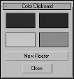
When selected, the Color Clipboard appears as a rollout in the Utilities panel and includes four color swatches. These color swatches can be dragged to other interfaces such as the Material Editor. Clicking on any of these swatches launches the Color Selector. The New Floater button opens a floatable Color Clipboard that holds 12 colors, shown in Figure 5.7. Right-clicking the color swatches opens a pop-up menu with Copy and Paste options. Using this clipboard, you can open and save color configurations. The files are saved as Color Clipboard files with the .ccb extension.
FIGURE 5.7 The Color Clipboard floating palette can hold 12 colors.

Using different creation methods
You actually have a couple of ways to create primitive objects by dragging in a viewport. With the first method, the first place you click sets the object's initial position. You then need to drag the mouse to define the object's first dimension and then click again to set each additional dimension, if needed. Primitive objects with a different number of dimensions require a different number of clicks and drags.
For example, a sphere is one of the simplest objects to create. To create a sphere, click in a viewport to set the location of the sphere's center, drag the mouse to the desired radius, and release the mouse button to complete. A Box object, on the other hand, requires a click-and-drag move to define the base (width and depth), and another drag-and-click move to set the height. If you ever get lost when defining these dimensions, check the Prompt Line to see what dimension the interface expects next.
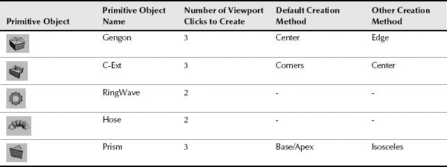
When you click a primitive object button, the Creation Method rollout appears and offers different methods for creating the primitives. For example, click the Sphere button, and the Creation Method rollout displays two options: Edge and Center. When you choose the Edge method, the first viewport click sets one edge of the sphere, and dragging and clicking again sets the diameter of the sphere. The default Center creation method defines the sphere's center location; dragging sets the sphere's radius. The creation method for each primitive can be different. For example, the Box primitive object has a creation method for creating perfect cubes, which require only a single click and drag. Table 5.1 shows the number of clicks required to create an object and the creation methods for each primitive object.
Tip
If you're dragging to create a primitive object and halfway through its creation you change your mind, you can right-click to eliminate the creation of the object.
TABLE 5.1 Primitive Object Creation Methods

Note
Some primitive objects, such as the Hedra, RingWave, and Hose, don't have any creation methods.
Using the Keyboard Entry rollout for precise dimensions
When creating a primitive object, you can define its location and dimensions by clicking in a viewport and dragging, or you can enter precise values in the Keyboard Entry rollout, located in the Create panel. Within this rollout, you can enter the offset XYZ values for positioning the origin of the primitive and the dimensions of the object. The offset values are defined relative to the active construction plane that is usually the Home Grid.
When all the dimension fields are set, click the Create button to create the actual primitive. You can create multiple objects by clicking the Create button several times. After a primitive is created, altering the fields in the Keyboard Entry rollout has no effect on the current object, but you can always use the Undo feature to try again.
Altering object parameters
The final rollout for all primitive objects is the Parameters rollout. This rollout holds all the various settings for the object. Compared to the Keyboard Entry rollout, which you can use only when creating the primitive, you can use the Parameters rollout to alter the primitive's parameters before or after the creation of the object. For example, increasing the Radius value after creating an object makes an existing sphere larger. This works only while the primitive mode is still enabled.
The parameters are different for each primitive object, but you can generally use them to control the dimensions, the number of segments that make up the object, and whether the object is sliced into sections. You can also select the Generate Mapping Coordinates option (which automatically creates material mapping coordinates that are used to position texture maps) and the Real-World Map Size option (which lets you define a texture's dimensions that are maintained regardless of the object size).
Note
After you deselect an object, the Parameters rollout disappears from the Create tab and moves to the Modify tab. You can make future parameter adjustments by selecting an object and clicking the Modify tab.
Recovering from mistakes and deleting objects
Before going any further, you need to be reminded how to undo the last action with the Undo menu command. The Undo (Ctrl+Z) menu command will undo the last action, whether it's creating an object or changing a parameter. The Redo (Ctrl+Y) menu command lets you redo an action that was undone.
Note
A separate undo feature for undoing a view change is available in the Views menu. The Views ![]() Undo View Change (Shift+Z) applies to any viewport changes like zooming, panning, and rotating the view.
Undo View Change (Shift+Z) applies to any viewport changes like zooming, panning, and rotating the view.
You can set the levels of undo in the General panel of the Preference Settings dialog box. If you click on the small arrow to the left of either the Undo button or the Redo button on the Quick Access toolbar, a list of recent actions is displayed. You can select any action from this list to be undone.
Tip
Another way to experiment with objects is with the Hold (Ctrl+H) and Fetch (Alt+Ctrl+F) features, also found in the Edit menu. The Hold command holds the entire scene, including any viewport configurations, in a temporary buffer. You can recall a held scene at any time using the Fetch command. This is a quick alternative to saving a file.
The Edit ![]() Delete menu command removes the selected object (or objects) from the scene. (The keyboard shortcut for this command is, luckily, the Delete key, because anything else would be confusing.)
Delete menu command removes the selected object (or objects) from the scene. (The keyboard shortcut for this command is, luckily, the Delete key, because anything else would be confusing.)
Tutorial: Exploring the Platonic solids
Among the many discoveries of Plato, an ancient Greek mathematician and philosopher, were the mathematical formulas that defined perfect geometric solids. A perfect geometric solid is one that is made up of polygon faces that are consistent throughout the object. The five solids that meet these criteria have come to be known as the Platonic solids.
Using Max, you can create and explore these interesting geometric shapes. Each of these shapes is available as a primitive object using the Hedra primitive object. The Hedra primitive object is one of the Extended Primitives.
To create the five Platonic solids as primitive objects, follow these steps:
- Open the Create panel, click the Geometry category button, and select Extended Primitives from the subcategory drop-down list. Click the Hedra button to enter Hedra creation mode, or select the Create
 Extended Primitives Hedra menu command.
 - Click in the Top viewport, and drag to the left to create a simple Tetrahedron object.
After the object is created, you can adjust its settings by altering the settings in the Parameters rollout.
Caution
Primitive parameters are available in the Create panel only while the new object is selected. If you deselect the new object, then the parameters are no longer visible in the Create panel, but you can access the object's parameters in the Modify panel.
- Select the Tetra option in the Parameters rollout, set the P value in the Family Parameters section to 1.0, and enter a value of 50 for the Radius. Be sure to press the Enter key after entering a value to update the object. Enter the name Tetrahedron in the Object Name field.
- Click and drag again in the Top viewport to create another Hedra object. In the Parameters rollout, select the Cube/Octa option, and enter a value of 1.0 in the Family Parameter's P field and a value of 50 in the Radius field. Name this object Octagon.
- Drag in the Top viewport to create another object. The Cube/Octa option is still selected. Enter a value of 1.0 in the Family Parameter's Q field this time, and set the Radius to 50. Name this object Cube.
- Drag in the Top viewport again to create the fourth Hedra object. In the Parameters rollout, select the Dodec/Icos option, enter a value of 1.0 in the P field, and set the Radius value to 50. Name the object Icosahedron.
- Drag in the Top viewport to create the final object. With the Dodec/Icos option set, enter 1.0 for the Q value, and set the Radius to 50. Name this object Dodecahedron.
- To get a good look at the objects, click the Perspective viewport, press the Zoom Extents button, and maximize the viewport by clicking the Min/Max Toggle (or press Alt+W) in the lower-right corner of the window.
Figure 5.8 shows the five perfect solid primitive objects. Using the Modify panel, you can return to these objects and change their parameters to learn the relationships among them. Later in this chapter, you can read about the Hedra primitive in greater detail.
FIGURE 5.8 The octagon, cube, tetrahedron, icosahedron, and dodecahedron objects; Plato would be amazed.

Exploring the Primitive Object Types
In the Create panel are actually two different subcategories of geometric primitives: Standard Primitives and Extended Primitives. These primitives include a diverse range of objects, from simple boxes and spheres to complex torus knots. You can create all these primitives from the Create panel.
Starting with the Standard Primitives
The Standard Primitives include many of the most basic and most used objects, including boxes, spheres, and cylinders. Figure 5.9 shows all the Standard Primitives.
FIGURE 5.9 The Standard Primitives: Box, Sphere, Cylinder, Torus, Teapot, Cone, GeoSphere, Tube, Pyramid, and Plane

Box
You can use the Box primitive to create regular cubes and boxes of any width, length, and height. Holding down the Ctrl key while dragging the box base creates a perfect square for the base. To create a cube, select the Cube option in the Creation Method rollout. A single click and drag completes the cube.
The Length, Width, and Height Segment values indicate how many polygons make up each dimension. The default is only one segment.
Sphere
Spheres appear everywhere from sports balls to planets in space. Spheres are also among the easiest primitives to create. After clicking the Sphere button, simply click and drag in a viewport.
In the Parameters rollout, the Segments value specifies the number of polygons that make up the sphere. The higher the number of segments, the smoother the sphere is. The default value of 32 produces a smooth sphere, and a value of 4 actually produces a diamond-shaped object. The Smooth option lets you make the sphere smooth or faceted. Faceted spheres are useful for identifying faces for modifications. Figure 5.10 shows five spheres. The one on the left has 32 Segments and the Smooth option turned on. The remaining spheres have the Smooth option disabled with Segment values of 32, 16, 8, and 4.
The Parameters rollout also lets you create hemispheres. The hemisphere shape is set by the Hemisphere value, which can range from 0.0 to 1.0, with 0 being a full sphere and 1 being nothing at all. (A value of 0.5 would be a perfect hemisphere.) With the Hemisphere value specified, you now have two options with which to deal with the unused polygons that make up the originating sphere: the Chop option, which removes the unused polygons, and the Squash option, which retains the polygons but “squashes” them to fit in the hemisphere shape.
FIGURE 5.10 Sphere primitives of various Segment values with the Smooth option turned on and off
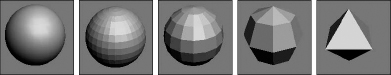
Figure 5.11 shows two hemispheres with Hemisphere values of 0.5. The Edged Faces option was enabled so you can see the polygon faces. The left hemisphere was created using the Chop option, and the right hemisphere was created with the Squash option. Notice how many extra polygons are included in the right hemisphere.
FIGURE 5.11 Creating hemispheres with the Chop and Squash options

The Slice option enables you to dissect the sphere into slices (like segmenting an orange). The Slice From and Slice To fields accept values ranging from 0 to 360 degrees. Figure 5.12 shows four spheres that have been sliced. Notice that because the Segments value hasn't changed, all slices have the same number of faces.
Note
You can use the Slice feature on several primitives, including the sphere, cylinder, torus, cone, tube, oiltank, spindle, chamfercyl, and capsule.
FIGURE 5.12 Using the Slice option to create sphere slices

The Base to Pivot parameter determines whether the position of the pivot point (or the point about which the object rotates) is at the bottom of the sphere or at the center. The default (with the Base to Pivot setting not enabled) sets the pivot point for the sphere at the center of the sphere.
Cylinder
You can use a cylinder in many places—for example, as a pillar in front of a home or as a car driveshaft. To create one, first specify a base circle and then a height. The default number of sides is 18, which produces a smooth cylinder. Height and Cap Segments values define the number of polygons that make up the cylinder sides and caps. The Smooth and Slice options work the same as they do with a sphere (see the preceding section).
Tip
If you don't plan on modifying the ends of the cylinder, make the Cap Segments equal to 1 to keep the model complexity down.
Torus
A torus (which is the mathematical name for a “doughnut”) is a ring with a circular cross section. To create a torus, you need to specify two radii values. The first is the value from the center of the torus to the center of the ring; the second is the radius of the circular cross section. The default settings create a torus with 24 segments and 12 sides. The Rotation and Twist options cause the sides to twist a specified value as the ring is circumnavigated.
Figure 5.13 shows some sample toruses with a Smooth setting of None. The first three have Segments values of 24, 12, and 6. The last two have Twist values of 90 and 360. The higher the number of segments, the rounder the torus looks when viewed from above. The default of 24 is sufficient to create a smooth torus. The number of sides defines the circular smoothness of the cross section.
FIGURE 5.13 Using the Segments and Twist options on a torus

The Parameters rollout includes settings for four different Smooth options. The All option smoothes all edges, and the None option displays all polygons as faceted. The Sides option smoothes edges between sides, resulting in a torus with banded sides. The Segment option smoothes between segment edges, resulting in separate smooth sections around the torus.
The Slice options work with a torus the same way as they do with the sphere and cylinder objects; see the “Sphere” section earlier in this chapter.
Teapot
Okay, let's all sing together, “I'm a little teapot, short and stout. . . .” The teapot is another object that, like the sphere, is easy to create. Within the Parameters rollout, you can specify the number of Segments, whether the surface is smooth or faceted, and which parts to display, including Body, Handle, Spout, and Lid.
Note
You may recognize most of these primitives as standard shapes, with the exception of the teapot. The teapot has a special place in computer graphics. In early computer graphics development labs, the teapot was chosen as the test model for many early algorithms. It is still included as a valuable benchmark for computer graphics programmers.
Cone
The Cone object, whether used to create ice cream cones or megaphones, is created exactly like the cylinder object except that the second cap can have a radius different from that of the first. You create it by clicking and dragging to specify the base circle, dragging to specify the cone's height, and then dragging again for the second cap to create a Cone.
In addition to the two cap radii and the Height, parameter options include the number of Height and Cap Segments, the number of Sides, and the Smooth and Slice options.
GeoSphere
The GeoSphere object is a sphere created by using fewer polygon faces than the standard Sphere object. This type of sphere spreads the polygon faces, which are all roughly equal in size, around the object, instead of concentrating them on either end like the normal Sphere object. This makes the GeoSphere a better choice for surface modeling because its polygon resolution is consistent. Geospheres also render more quickly and have faster transformation times than normal spheres. One reason for this is that a GeoSphere uses triangle faces instead of square faces.
In the Parameters rollout are several Geodesic Base Type options, including Tetra, Octa, and Icosa. The Tetra type is based on a four-sided tetrahedron, the Octa type is based on an eight-sided Octahedron, and the Icosa type is based on the 20-sided Icosahedron. Setting the Segment value to 1 produces each of these Hedra shapes. Each type aligns the triangle faces differently.
GeoSpheres also have the same Smooth, Hemisphere, and Base to Pivot options as the Sphere primitive. Selecting the Hemisphere option changes the GeoSphere into a hemisphere, but you have no additional options like Chop and Squash. GeoSphere primitives do not include an option to be sliced.
Tutorial: Comparing Spheres and GeoSpheres
To prove that GeoSpheres are more efficient than Sphere objects, follow these steps:
- Create a normal Sphere, and set its Segment value to 4.
- Next to the Sphere object, create a GeoSphere object with a Tetra Base Type and the number of Segments set to 4.
- Create another GeoSphere object with the Octa Base Type and 4 Segments.
- Finally, create a GeoSphere with the Icosa Base Type and 4 Segments.
Figure 5.14 shows these spheres as a comparison. The normal sphere, shown to the left, looks like a diamond, but the GeoSpheres still resemble spheres. Notice that the Icosa type GeoSphere, shown on the right, produces the smoothest sphere.
FIGURE 5.14 Even with a similar number of segments, GeoSpheres are much more spherical.

Tube
The Tube primitive is useful any time you need a pipe object. You can also use it to create ring-shaped objects that have rectangular cross sections. Creating a Tube object is very similar to the Cylinder and Cone objects. Tube parameters include two radii for the inner and outer tube walls. Tubes also have the Smooth and Slice options.
Pyramid
Pyramid primitives are constructed with a rectangular base and triangles at each edge that rise to meet at the top, just like the ones in Egypt, only easier to build. Two different creation methods are used to create the base rectangle. With the Base/Apex method, you create the base by dragging corner to corner, and with the Center method, you drag from the base center to a corner.
The Width and Depth parameters define the base dimensions, and the Height value determines how tall the pyramid is. You can also specify the number of segments for each dimension.
Plane
The Plane object enables you to model the Great Plains (good pun, eh?). The Plane primitive creates a simple plane that looks like a rectangle, but it includes Multiplier parameters that let you specify the size of the plane at render time. This feature makes working in a viewport convenient because you don't have to worry about creating a huge plane object representing the ground plane that makes all other scene objects really small in comparison.
Tip
Dense plane objects can be made into a terrain by randomly altering the height of each interior vertex with a Noise modifier.
The Plane primitive includes two creation methods: Rectangle and Square. The Square method creates a perfect square in the viewport when dragged. Holding down the Ctrl key while creating a Plane object also creates a perfect square. You can also define the Length and Width Segments, but the real benefits of the Plane object are derived from the use of the Render Multipliers.
The Scale Multiplier value determines how many times larger the plane should be at render time. Both Length and Width are multiplied by equal values. The Density Multiplier specifies the number of segments to produce at render time. The Total Faces value lets you know how many polygons are added to the scene using the specified Density Multiplier value.
Using these multipliers, you can create a small Plane object in the scene that automatically increases to the size and density it needs to be when rendered. This allows you to use the Zoom Extents button to see all objects without having a huge Plane object define the extents.
Extended Primitives
You access the Extended Primitives by selecting Extended Primitives in the subcategory drop-down list in the Create panel. These primitives aren't as generic as the Standard Primitives, but are equally useful, as shown in Figure 5.15.
FIGURE 5.15 The Extended Primitives: Hedra, ChamferBox, OilTank, Spindle, Gengon, RingWave, Hose, Torus Knot, ChamferCyl, Capsule, L-Ext, C-Ext, and Prism

Hedra
Hedras, or Polyhedra, form the basis for a class of geometry defined by fundamental mathematical principles. In addition to Plato, Johannes Kepler used these Polyhedra as the basis for his famous “Harmony of the Spheres” theory. The Hedra primitives available in Max are Tetrahedron, Cube/Octahedron, Dodecahedron/Icosahedron, and two Star types called Star1 and Star2. From these basic Polyhedra, you can create many different variations.
The Family section options determine the shape of the Hedra. Each member of a Hedra pair is mathematically related to the other member. The Family Parameters include P and Q values. These values change the Hedra between the two shapes that make up the pair. For example, if the Family option is set to Cube/Octa, then a P value of 1 displays an Octagon, and a Q value of 1 displays a Cube. When both P and Q values are set to 0, the shape becomes an intermediate shape somewhere between a Cube and an Octagon. Because the values are interrelated, only one shape of the pair can have a value of 1 at any given time. Both P and Q cannot be set to 1 at the same time.
Figure 5.16 shows each of the basic Hedra Families in columns from left to right: Tetra, Cube/Octa, Dodec/Icos, Star1, and Star2. The top row has a P value of 1 and a Q value of 0, the middle row has both P and Q set to 0, and the bottom row sets P to 0 and Q to 1. Notice that the middle row shapes are a combination of the top and bottom rows.
The relationship between P and Q can be described in this manner: When the P value is set to 1 and the Q value is set to 0, one shape of the pair is displayed. As the P value decreases, each vertex becomes a separate face. The edges of these new faces increase as the value is decreased down to 0. The same holds true for the Q value.
FIGURE 5.16 The Hedra Families with the standard shapes in the top and bottom rows and the intermediate shapes in the middle row

Tip
Altering the P and Q parameters can create many unique shapes. For each Hedra, try the following combinations: P = 0, Q = 0; P = 1, Q = 0; P = 0, Q = 1; P = 0.5, Q = 0.5; P = 0.5, Q = 0; P = 0, Q = 0.5. These represent the main intermediate objects.
As the geometry of the objects changes, the Hedra can have as many as three different types of polygons making up the faces. These polygons are represented by the P, Q, and R Axis Scaling values. Each type of face can be scaled, creating sharp points extending from each face. If only one unique polygon is used for the faces, then only one Axis Scaling parameter is active. The Reset button simply returns the Axis Scaling value to its default at 100. For example, using the R Axis Scaling value, pyramid shapes can be extended from each face of a cube.
Figure 5.17 shows some results of using the Axis Scaling options. One of each family type has been created and displayed in the top row for reference. The bottom row has had an axis scaled to a value of 170. This setting causes one type of polygon face to be extended, thereby producing a new shape.
FIGURE 5.17 Hedras with extended faces, compliments of the Axis Scaling option

The Vertices parameter options add more vertices and edges to the center of each extended polygon. The three options are Basic, which is the default and doesn't add any new information to the Hedra; Center, which adds vertices to the center of each extended polygon; and Center and Sides, which add both center vertices and connecting edges for each face that is extended using the Axis Scaling options. With these options set, you can extend the polygon faces at your own discretion.
Way at the bottom of the Parameters rollout is the Radius value, which generally sets the size of the hedra object.
ChamferBox
A chamfered object is one whose edges have been smoothed out, so a ChamferBox primitive is a box with beveled edges. The parameter that determines the amount of roundness applied to an edge is Fillet. In many ways, this object is just a simple extension of the Box primitive.
The only additions in the Parameters rollout are two fields for controlling the Fillet dimension and the Fillet Segments. Figure 5.18 shows a ChamferBox with Fillet values of 0, 5, 10, 20, and 30 and the Smooth option turned on.
FIGURE 5.18 A ChamferBox with progressively increasing Fillet values

Cylindrical Extended Primitives
The Extended Primitives include several objects based on the Cylinder primitive that are very similar. The only real difference is the shape of the caps at either end. These four similar objects include the OilTank, Spindle, ChamferCyl, and Capsule. Figure 5.19 shows these similar objects side by side.
FIGURE 5.19 Several different cylindrical Extended Primitive objects exist, including OilTank, Spindle, ChamferCyl, and Capsule.

OilTank
OilTank seems like a strange name for a primitive. This object is essentially the Cylinder primitive with dome caps like you would see on a diesel truck transporting oil. The Parameters rollout includes an additional option for specifying the Cap Height. The Height value can be set to indicate the entire height of the object with the Overall option or the height to the edge of the domes using the Centers option. The only other new option is Blend, which smoothes the edges between the cylinder and the caps. All cylindrical primitives can also be sliced just like the sphere object.
Spindle
The Spindle primitive is the same as the OilTank primitive, except that the dome caps are replaced with conical caps. All other options in the Parameters rollout are identical to the OilTank primitive.
ChamferCyl
The ChamferCyl primitive is very similar to the ChamferBox primitive, but is applied to a cylinder instead of a box. The Parameters rollout includes some additional fields for handling the Fillet values.
Capsule
The Capsule primitive is yet another primitive based on the cylinder, but this time with hemispherical caps. This object resembles the OilTank primitive very closely. The only noticeable difference is in the border between the cylinder and caps.
Gengon
The Gengon primitive creates and extrudes regular polygons such as triangles, squares, and pentagons. There is even an option to Fillet (or smooth) the edges. To specify which polygon to use, enter a value in the Sides field.
Figure 5.20 shows five simple Gengons with different numbers of edges.
FIGURE 5.20 Gengon primitives are actually just extruded regular polygons.

RingWave
The RingWave primitive is a specialized primitive that you can use to create a simple gear or a sparkling sun. It consists of two circles that make up a ring. You can set the circle edges to be wavy and even fluctuate over time. You can also use RingWaves to simulate rapidly expanding gases that would result from a planetary explosion. If you're considering a Shockwave effect, then you should look into using a RingWave primitive.
The Radius setting defines the outer edge of the RingWave, and the Ring Width defines the inner edge. This ring can also have a Height. The Radial and Height Segments and the number of Sides determine the complexity of the object.
The RingWave Timing controls set the expansion values. The Start Time is the frame where the ring begins at zero, the Grow Time is the number of frames required to reach its full size, and the End Time is the frame where the RingWave object stops expanding. The No Growth option prevents the object from expanding, and it remains the same size from the Start frame to the End frame. The Grow and Stay option causes the RingWave to expand from the Start Time until the Grow Time frame is reached and remains full grown until the End Time. The Cyclic Growth begins expanding the objects until the Grow Time is reached. It then starts again from zero and expands repeatedly until the End Time is reached.
The last two sections of the Parameters rollout define how the inner and outer edges look and are animated. If the Edge Breakup option is on, then the rest of the settings are enabled. These additional settings control the number of Major and Minor Cycles, the Width Flux for these cycles, and the Crawl Time, which is the number of frames to animate.
The Surface Parameters section includes an option for creating Texture Coordinates, which are the same as mapping coordinates for applying textures. There is also an option to Smooth the surface of the object.
Figure 5.21 shows five animated frames of a RingWave object with both Inner and Outer Edge Breakup settings. Notice that the edges change over the different frames.
FIGURE 5.21 Five frames of a rapidly expanding and turbulent RingWave object

Tutorial: Creating a pie
This tutorial provides a very different recipe for creating a pie using a RingWave object. Although the RingWave object can be animated, you also can use it to create static objects such as this pie, or moving objects such as a set of gears.
To create a pie using the RingWave object, follow these steps:
- Select Create Extended Primitives RingWave, and drag in the Top viewport to create a RingWave object.
- In the Parameters rollout, set the Radius to 115, the Ring Width to 90, and the Height to 30.
- In the RingWave Timing section, select the No Growth option. Then enable the Outer Edge Breakup option, set the Major Cycles to 25, the Width Flux to 4.0, and the Minor Cycles to 0.
- Enable the Inner Edge Breakup option. Set the Major Cycles to 6, the Width Flux to 15, and the Minor Cycles to 25 with a Width Flux of 10.
Figure 5.22 shows a nice pie object as good as Grandmother made. You can take this pie one step further by selecting Modifiers ![]() Parametric Deformers
Parametric Deformers ![]() Taper to apply the Taper modifier and set the Amount to 0.1.
Taper to apply the Taper modifier and set the Amount to 0.1.
FIGURE 5.22 This pie object was created using the RingWave object.

Prism
The Prism primitive is essentially an extruded triangle. If you select the Base/Apex creation method, then each of the sides of the base triangle can have a different length. With this creation method, the first click in the viewport sets one edge of the base triangle, the second click sets the opposite corner of the triangle that affects the other two edges, and the final click sets the height of the object.
The other creation method is Isosceles, which doesn't let you skew the triangle before setting the height.
Torus Knot
A Torus Knot is similar to the Torus covered earlier, except that the circular cross section follows a 3D curve instead of a simple circle. The method for creating the Torus Knot primitive is the same as that for creating the Torus. The Parameters rollout even lets you specify the base curve to be a circle instead of a knot. A knot is a standard, mathematically defined 3D curve.
Below the Radius and Segment parameters are the P and Q values. These values can be used to create wildly variant Torus Knots. The P value is a mathematical factor for computing how the knot winds about its vertical axis. The maximum value is 25, which makes the knot resemble a tightly wound spool. The Q value causes the knot to wind horizontally. It also has a maximum value of 25. Setting both values to the same number results in a simple circular ring.
Figure 5.23 shows some of the beautiful shapes that are possible by altering the P and Q values of a Torus Knot. These Torus Knots have these values: the first has P = 3, Q = 2; the second has P = 1, Q = 3; the third has P = 10, Q = 15; the fourth has P = 15, Q = 20; and the fifth has P = 25, Q = 25.
FIGURE 5.23 Various Torus Knots display the beauty of mathematics.

When the Base Curve is set to Circle, like those in Figure 5.23, the P and Q values become disabled, and the Warp Count and Warp Height fields become active. These fields control the number of ripples in the ring and their height. Figure 5.24 shows several possibilities. From left to right, the settings are Warp Count = 5, Warp Height = 0.5; Warp Count = 10, Warp Height = 0.5; Warp Count = 20, Warp Height = 0.5; Warp Count = 50, Warp Height = 0.5; and Warp Count = 100, Warp Height = 0.75.
FIGURE 5.24 Torus Knots with a Circle Base Curve are useful for creating impressive rings.

In addition to the Base Curve settings, you can also control several settings for the Cross Section. The Radius and Sides values determine the size of the circular cross section and the number of segments used to create the cross section. The Eccentricity value makes the circular cross section elliptical by stretching it along one of its axes. The Twist value rotates each successive cross section relative to the previous one creating a twisting look along the object. The Lumps value sets the number of lumps that appear in the Torus Knot, and the Lump Height and Offset values set the height and starting point of these lumps.
The Smooth options work just like those for the Torus object by smoothing the entire object, just the sides, or none. You can also set the U and V axis Offset and Tiling values for the mapping coordinates.
L-Ext
The L-Ext primitive stands for L-Extension. You can think of it as two rectangular boxes connected at right angles to each other. To create an L-Ext object, you need to first drag to create a rectangle that defines the overall area of the object. Next, you drag to define the Height of the object, and finally, you drag to define the width of each leg.
The Parameters rollout includes dimensions for Side and Front Lengths, Side and Front Widths, and the Height. You can also define the number of Segments for each dimension.
C-Ext
The C-Ext primitive is the same as the L-Ext primitive with an extra rectangular box. The C shape connects three rectangular boxes at right angles to each other.
The Parameters rollout includes dimensions for Side, Front, and Back Lengths and Widths, and the Height. You can also define the number of Segments for each dimension. These primitives are great if your name is Clive Logan or Carrie Lincoln. No, actually, these primitives are used to create architectural beams.
Hose
The Hose primitive is a flexible connector that can be positioned between two other objects. It acts much like a spring but has no dynamic properties. In the Hose Parameters rollout, you can specify the Hose as a Free Hose or Bound to Object Pivots. If the Free Hose option is selected, you can set the Hose Height. If the Bound to Object Pivots option is selected, then two Pick Object buttons appear for the Top and Bottom objects. Once bound to two objects, the hose stretches between the two objects when either is moved. You can also set the Tension for each bound object.
For either the Bound Hose or Free Hose, you can set the number of Segments that make up the hose; whether the flexible section is enabled; to smooth along the Sides, Segments, neither, or all; whether the hose is Renderable; and to Generate Mapping Coordinates for applying texture maps. If the flexible section is enabled, then you can set where the flexible section Starts and Ends, the number of Cycles, and its Diameter.
You can also set the Hose Shape to Round, Rectangular, or D-Section. Figure 5.25 shows a flexible hose object bound to two sphere objects.
FIGURE 5.25 The Hose object flexes between its two bound objects.

Tutorial: Creating a bendable straw
If you've ever found yourself modeling a juice box (or drinking from a juice box and wondering, “How would I model this bendable straw?”), then this tutorial is for you. The nice part about the Hose primitive is that once you've created the model, you can reposition the straw, and the bend changes as needed, just like a real straw.
To create a bendable straw, follow these steps:
- Open the Bendable straw.max file from the Chap 05 directory on the CD.
This file includes two Tube primitives to represent the top and bottom portions of a straw. I've oriented their pivot points so the Z-axis points toward where the Hose primitive will go.
- Select Create Extended Primitives Hose, and drag in the Top viewport close to where the two straws meet. Select the Bound to Object Pivots option, click on the Pick Top Object button, and select the top Tube object. Then click on the Pick Bottom Object button, and select the bottom Tube object. This step positions the Hose object between the two Tube pieces.
- In the Hose Parameters rollout, set the Tension for the Top object to 35 and the Tension for the bottom object to 10.0. Set the Segments to 40, the Starts value to 0, the Ends value to 100, the Cycles to 10, and the Diameter to 24. Make sure that the Renderable option is enabled, and enable the Round Hose option with a Diameter of 20.0.
Figure 5.26 shows the completed bendable straw created using a Hose primitive.
FIGURE 5.26 Use the Hose primitive to connect two objects.

Modifying object parameters
Primitive objects provide a good starting point for many of the other modeling types. They also provide a good way to show off parameter-based modeling.
All objects have parameters. These parameters help define how the object looks. For example, consider the primitive objects. The primitive objects contained in Max are parametric. Parametric objects are mathematically defined, and you can change them by modifying their parameters. The easiest object modifications to make are simply changing these parameters. For example, a sphere with a radius of 4 can be made into a sphere with a radius of 10 by simply typing a 10 in the Radius field. The viewports display these changes automatically when you press the Enter key.
Note
When an object is first created, its parameters are displayed in the Parameters rollout of the Create panel. As long as the object remains the current object, you can modify its parameters using this rollout. After you select a different tool or object, the Parameters rollout is no longer accessible from the Create panel, but if you select the object and open the Modify panel, all the parameters can be changed for the selected object.
Tutorial: Filling a treasure chest with gems
I haven't found many treasure chests lately, but if I remember correctly, they are normally filled with bright, sparkling gems. In this tutorial, you'll fill the chest with a number of Hedra primitives and alter the object properties in the Modify panel to create a diverse offering of gems.
To create a treasure chest with many unique gems, follow these steps:
- Open the Treasure chest of gems.max file from the Chap 05 directory on the CD.
This file includes a simple treasure chest model.
- Select Create Extended Primitives Hedra to open the Extended Primitives subcategory in the Create panel. At the top of the Object Type rollout, enable the AutoGrid option and select the Hedra button.
The AutoGrid option creates all new objects on the surface of other objects.
- Create several Hedra objects.
The size of the objects doesn't matter at this time.
- Open the Modify panel, and select one of the Hedra objects.
- Alter the values in the Parameters rollout to produce a nice gem.
- Repeat Step 5 for all Hedra objects in the chest.
Figure 5.27 shows the resulting chest with a variety of gems.
FIGURE 5.27 A treasure chest full of gems quickly created by altering object parameters

Using Architecture Primitives
If you wander about the various departments at Autodesk, you run into several groups that deal with products for visualizing architecture, including the well-known product AutoCAD. This product is used by a vast number of engineers and architects to design the layouts for building physical structures.
Along with AutoCAD is Revit, another very popular package that would be considered a close sibling to Max. AutoCAD Revit is used to create visualizations of AutoCAD data and, like Max, deals with modeling, rendering, and shading 3D objects. In fact, many of the new features found in Max were originally developed for Revit.
Using AEC Objects
Included in the features that have migrated over from the AutoCAD world are all the various architectural objects commonly found in buildings. These objects can all be found in the Create ![]() AEC Objects menu. The AEC Objects menu includes many different architecture primitives: Foliage, Railings, Walls, Doors, Stairs, and Windows.
AEC Objects menu. The AEC Objects menu includes many different architecture primitives: Foliage, Railings, Walls, Doors, Stairs, and Windows.
Foliage
The Foliage category includes several different plants, all listed in the Favorite Plants rollout and shown in Figure 5.28. The available plants include a Banyan tree, Generic Palm, Scotch Pine, Yucca, Blue Spruce, American Elm, Weeping Willow, Euphorbia, Society Garlic, Big Yucca, Japanese Flowering Cherry, and Generic Oak.
Caution
The various foliage objects are large models that can quickly slow down the scene if multiple copies are added to a scene. For example, a single Banyan tree has more than 100,000 polygons. Adding several such trees to your scene can make it quite slow.
FIGURE 5.28 The Favorite Plants rollout shows thumbnails of the various plants.

At the bottom of the Favorite Plants rollout is a button called Plant Library that opens a dialog box where you can see the details of all the plants, including the total number of faces. The winner is the Banyan tree with 100,000 faces. Using the Parameters rollout, you can set the Height, Density, and Pruning values for each of these plants. Also, depending on the tree type, you can select to show the Leaves, Trunk, Fruit, Branches, Flowers, and Roots, and you can set the Level of Detail to Low, Medium, or High.
Tip
After some time, the Foliage set starts to feel rather limited. You can use the Help ![]() 3ds Max on the Web
3ds Max on the Web ![]() Download Vegetation menu to access the Autodesk Seek website. This site holds a repository of architecturally related objects, including a huge selection of plants and trees.
Download Vegetation menu to access the Autodesk Seek website. This site holds a repository of architecturally related objects, including a huge selection of plants and trees.
Railings
The Railings option lets you pick a path that the railing will follow. You can then select the number of Segments to use to create the railing. For the Top Rail, you can select to use No Railing or a Round or Square Profile and set its Depth, Width, and Height. You can also set parameters for the Lower Rails, Posts (which appear at either end), and Fencing (which are the vertical slats that support the railing).
The Lower Rails, Posts, and Fencing sections feature an icon that can be used to set the Spacing of these elements. The Spacing dialog box that opens looks like the same dialog box that is used for the Spacing Tool, where you can specify a Count, Spacing value, and Offsets.
Walls
Walls are simple, with parameters for Width and Height. You can also set the Justification to Left, Center, or Right. The nice part about creating wall objects is that you can connect several walls together just like the Line tool. For example, creating a single wall in the Top viewport extends a connected wall from the last point where you clicked that is connected to the previous wall. Right-click to exit wall creation mode. Figure 5.29 shows a room of walls created simply by clicking at the intersection points in the Top view.
FIGURE 5.29 Rooms of walls can be created simply by clicking where the corners are located.

Doors
The Doors category includes three types of doors: Pivot, Sliding, and BiFold. Each of these types has its own parameters that you can set, but for each of these door types you can set its Height, Width, and Depth dimensions and the amount the door is Open.
Be aware when creating doors that Doors have two different Creation Methods—Width/Depth/Height and Width/Height/Depth. The first is the default, and it requires that the first click sets the Width, the second click sets the Depth, and the third click sets the Height. The Parameters rollout includes options to flip the direction in which the door opens. This is very handy if you position your door incorrectly.
Stairs
The Stairs category includes four types of stairs: LType, Spiral, Straight, and UType. For each type, you can select Open (single slats with no vertical backing behind the stairs), Closed (each stair includes a horizontal and vertical portion), or Box (the entire staircase is one solid object). For each type, you also can control the parameters for the Carriage (the center support that holds the stairs together), Stringers (the base boards that run along the sides of the stairs), and Railings.
The Rise section determines the overall height of the staircase. It can be set by an Overall height value, a Riser Height value (the height of each individual stair), or by a Riser Count (the total number of stairs). You also can specify the Thickness and Depth of the stairs.
Windows
The Windows category includes six types of windows: Awning, Casement, Fixed, Pivoted, Projected, and Sliding. As with doors, you can choose from two different Creation Methods. The default Creation Method creates windows with Width, then Depth, and then Height. Parameters include the Window and Frame dimensions, the Thickness of the Glazing, and Rails and Panels. You can also open all windows, except for the Fixed Window type.
Tutorial: Adding stairs to a clock tower building
I'll leave the architectural design to the architects, but for this example, you'll create a simple staircase and add it to the front of a clock tower building.
To add stairs to a building, follow these steps.
- Open the Clock tower building.max file from the Chap 05 directory on the CD. This file includes a building with a clock tower extending from its center, but the main entrance is empty.
- Select Create AEC Objects Straight Stair. Click and drag in the Top viewport from the location where the lower-left corner of the stair is located and drag to the upper-left corner of the stairs where the stairs meet the entryway into the building to set the stair's length. Then drag across to set the stairs’ width and click at the opposite side of the entryway. Then drag downward in the Left viewport to set the stairs’ height and click. Then right-click in the Top viewport to exit Stairs creation mode.
- With the stairs selected, click the Select and Move (W) button in the main toolbar and drag the stairs in the Front viewport until they align with the front of one side of the entryway.
- Open the Modify panel, and select the Box option in the Parameters rollout. Then adjust the Overall Rise value so it matches the entryway.
- Select Tools Mirror, and select the Copy option with an Offset of around –140 about the X-Axis. Click OK.
Figure 5.30 shows the clock tower building with stairs.
FIGURE 5.30 The AEC Objects category makes adding structural objects like stairs easy.

Summary
Primitives are the most basic shapes and often provide a starting point for more ambitious modeling projects. The two classes of primitives—Standard and Extended—provide a host of possible objects. This chapter covered the following topics:
- The basics of creating primitives by both dragging and entering keyboard values
- How to name objects and set and change the object color
- The various creation methods for all the primitive objects
- The various primitives in both the Standard and Extended subcategories
- The possible parameters for each of the primitive objects
- Creating AEC Objects, including plants, railings, doors, and windows
Now that you know how to create objects, you can focus on selecting them after they're created, which is what the next chapter covers. You can select objects in numerous ways. Layers and setting object properties are also discussed.