
CHAPTER 14
Using the Graphite Modeling Tools and Painting with Objects
Working with the Graphite Modeling tools
Using the Freeform tools
Selecting specific subobjects
Painting with objects
The previous chapter covered everything you need to know about modeling with polygons, but the problem with the polygon workflow is the ping-pong effect of moving back and forth between the current model and the Command Panel. Although you can float the Command Panel or even use the quad menus to access most of these commands, the Max developers have presented an entirely new workflow based on the new Ribbon interface.
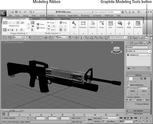
The Ribbon sits conveniently above the viewports, but you can pull off and float any of the individual panels as needed. The Ribbon panels are dynamic, so only those tools that work with the current selection are presented. This places the tools you need right in front of you when you need them.
The Ribbon is populated with all the features for working with Editable Poly objects that are found in the Command Panel. It also includes a large number of brand-new tools for selecting and working with polygon objects. These tools collectively are called the Graphite Modeling tools.
The Ribbon also is home to several additional panels of tools that allow you to paint deformations into your models, make unique selections, and select and paint with objects using brushes. The best part of these new tools is that they all eliminate the ping-pong effect. Our necks thank you, Autodesk.
Working with the Graphite Modeling Tools
![]() The Ribbon interface, shown in Figure 14.1, can be turned on and off using a button on the main toolbar or using the Customize
The Ribbon interface, shown in Figure 14.1, can be turned on and off using a button on the main toolbar or using the Customize ![]() Show UI
Show UI ![]() Show Ribbon menu. When enabled, the button turns yellow and the Ribbon appears in the same state it was in the last time it was opened. By double-clicking the Ribbon title bar, you can switch among displaying just the top tabs; just the tabs and panel titles; just the tabs, panel titles, and panel buttons; or the entire panel. This is great if you want to keep the Ribbon around but hide most of the buttons.
Show Ribbon menu. When enabled, the button turns yellow and the Ribbon appears in the same state it was in the last time it was opened. By double-clicking the Ribbon title bar, you can switch among displaying just the top tabs; just the tabs and panel titles; just the tabs, panel titles, and panel buttons; or the entire panel. This is great if you want to keep the Ribbon around but hide most of the buttons.
Cross-Reference
You can learn more details on working with the Ribbon interface in Chapter 1, “Exploring the Max Interface.”
When expanded, the Graphic Modeling Tools tab shows several panels of tools. Each of these panels can be separated from the Ribbon and floated independently. You also can rearrange the panels by dragging them to a new position. If the icons displayed within a panel don't fit, a small downward-pointing arrow offers access to the additional tools.
All the panels and tools that make up the Ribbon are adaptable and change depending on the subobject mode you select. Only the relevant tools are visible, which saves space and makes it easier to locate the tool you want to use.
On the CD-ROM
If you don't like the layout of the tools in the Ribbon, you can customize your own panels of tools, which is covered in Bonus Chapter 22, “Customizing the Max Interface.”
FIGURE 14.1 The Ribbon holds several panels of modeling tools.
If you right-click the Ribbon's title bar, you can access a pop-up menu of options to hide and show different tabs and panels. There is also a Ribbon Configuration that includes options for customizing the Ribbon, loading and saving custom configurations, and switching to a vertically oriented Ribbon.
Using the Polygon Modeling panel
The Graphite Modeling tools are exclusive to Editable Poly objects or objects with the Edit Poly modifier applied. If you select any other type of object with the Ribbon open, all the buttons are disabled. However, two options are available in the Polygon Modeling panel of the Graphite Modeling Tools tab. These options are to Convert to Poly and Apply Edit Poly Mod. These commands convert the selected object to an Editable Poly object or apply an Edit Poly modifier and automatically open the Modify panel.
After an Editable Poly object or an object with the Edit Poly modifier applied is selected, the subobject modes can be selected from the top of the Graphite Modeling Tools panel. The Polygon Modeling panel, shown in Figure 14.2, includes options that work with the Modifier Stack including collapsing the stack, pinning the stack, and moving up and down between modifiers. The Show End Result button lets you see the object with all stack modifiers applied and options that apply to all subobject modes. A button in this panel lets you toggle the Command Panel off.
FIGURE 14.2 The Ribbon's Polygon Modeling panel includes options for determining which subobjects are selected.
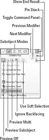
The Polygon Modeling panel also includes buttons for turning on and off subobject selection preview and for ignoring backfacing. The Use Soft Selection button enables you to select a feathered group of subobjects. When enabled, the Soft panel appears, as shown in Figure 14.3.
Using the Soft panel, you can enable Edit mode, which lets you interactively change the Falloff, Pinch, and Bubble settings. When the Edit button is enabled, the cursor looks like two circles. This is Falloff mode, and dragging the mouse changes the amount of falloff for the soft selection. If you click in the viewport, the cursor changes to a peak indicating Pinch edit mode. Click again to access Bubble edit mode, which looks like an upside-down letter U. Continue to click to cycle through these edit modes. These values also can be set in the Soft panel using the various spinner controls.
Cross-Reference
Using the Soft Selection features is covered in Chapter 10, “Accessing Subobjects and Using Modeling Helpers.”
The Paint button in the Soft panel opens the PaintSS panel, also shown in Figure 14.3, with buttons for blurring, reverting, and opening the Painter Options dialog box, which holds the brush settings. You also can set the Value, Size, and Strength of the soft selection brush.
The Use Edge Distance option lets you select adjacent edges to the current selection rather than using a falloff amount.
FIGURE 14.3 The Soft and PaintSS panels let you control how soft selections are made.

Generate Topology
Located at the bottom of the Ribbon's Polygon Modeling panel is an option to Generate Topology. This option opens the Topology pop-up panel, shown in Figure 14.4, showing several patterns. Selecting a pattern applies the selected pattern to the selected object or to the object's subobject selection if you hold down the Shift key.
FIGURE 14.4 The Topology pop-up panel lets you choose a pattern to apply to the object.
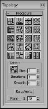
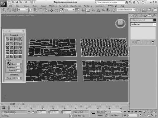
The Size, Iterations, and Smooth values let you configure the selected pattern. The ScrapVerts button removes any vertices with two edges going to it. The Plane button creates a simple plane object where the S value sets the resolution. Figure 14.5 shows four planes with different topologies applied.
FIGURE 14.5 Changing a plane's topology gives a unique set of faces to work with.
Using the Symmetry tools
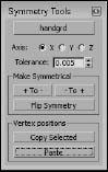
The Polygon Modeling panel also holds a link for accessing the Symmetry tools. This command opens the Symmetry Tools dialog box, shown in Figure 14.6. Using this dialog box, you can select an object with the top button and automatically copy the changes on either side of any axis to the opposite side with the + to - and - to + buttons. You also can use the Flip Symmetry button to switch the moved subobjects to the opposite side of the model.
The Copy Selected button lets you copy the position of an entire object or of just the selected vertices and paste them onto another object with the same number of vertices.
FIGURE 14.6 The Symmetry Tools dialog box lets you mirror subobject movements across an axis.
Tutorial: Building a Skateboard wheel
Starting with a simple sphere, you can quickly create a symmetrical skateboard wheel using the Symmetry tools.
To create a skateboard wheel, follow these steps:
- Use the Create
 Standard Primitives Sphere menu and drag in the Front viewport to create a sphere object.
 - Open the Graphite Modeling Tools by clicking its button in the main toolbar. Then select the Convert to Poly option from the Polygon Modeling panel in the Ribbon.
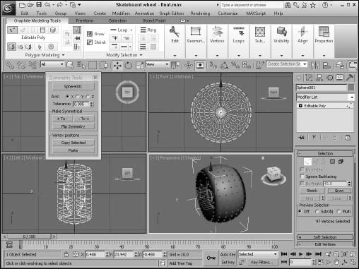
- Select the Symmetry Tools option in the Polygon Modeling panel, click the top button in the Symmetry Tools dialog box, and pick the sphere object.
- Select the Vertex subobject mode in the Polygon Modeling panel and drag over the top four rows of vertices in the Top viewport. Then drag with the Move tool downward in the Top viewport.
- Back in the Symmetry Tools dialog box, enable the Z Axis and click the - to + button to symmetrically copy the moved vertices, as shown in Figure 14.7.
FIGURE 14.7 The skateboard wheel is symmetrical and ready to roll.
Using the Modify Selection panel
The Ribbon also holds tools for making Loop and Ring selections. These tools are found in the Modify Selection panel, shown in Figure 14.8. When a loop or ring is selected, there are also buttons for growing and shrinking the adjacent rows or columns. There are also tools called Loop Mode and Ring Mode that cause the entire edge loop or edge ring to be automatically selected when a single edge is picked when enabled. A text label appears in the viewport when LoopMode is enabled. Tools called Dot Loop and Dot Ring let an edge loop and edge ring with gaps be selected. The Ribbon's Loop and Ring tools also allow you to select rows and columns of vertices and faces.
Note
The Modify Selection panel is only visible when a subobject mode is enabled.
FIGURE 14.8 The Ribbon's Modify Selection panel includes tools for working with loops and rings.
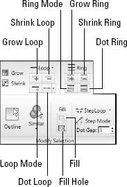
The Modify Selection panel also includes these tools: Outline, which selects all subobjects surrounding the current selection; Similar, which selects all subobjects that are similar to the current selection, including Edge Count, Edge Length, Face Count, Face Areas, and Normal Direction; and Fill, which selects all subobjects that are within the selected subobjects or within the current outlined selection. The Fill option lets you pick two vertices that are diagonally across from each other, and then all interior vertices between the two vertices are selected to make a square area.
The StepLoop option lets you select two subobjects within the same loop, and then all subobjects between the two are selected. When Step Mode is enabled, you can pick two subobjects in the same loop and all subobjects between the two are selected. This continues for all additional selections within the same loop until Step Mode is disabled again.
Tip
Using the Shift key, you can select loops of subobjects even more quickly. If you select a single vertex, edge, or polygon, and then hold down the Shift key and click on an adjacent subobject, the entire loop or ring of subobjects is automatically selected.
Editing geometry
When no subobject modes are selected, several Ribbon panels are available, as shown in Figure 14.9. These panels contain many of the same features that are found in the Edit Geometry rollout in the Command Panel. Features contained here include, among many others, the ability to create new subobjects, attach subobjects to the mesh, weld vertices, chamfer vertices, slice, explode, and align. These panels are available regardless of the subobject mode that is selected, but some of these tools are disabled depending on the subobject mode that you select.
FIGURE 14.9 The Ribbon includes many general-purpose editing features that are always available.
Many of the tools, such as Relax, MSmooth, Tessellate, PConnect, and Quadrify All, include options for accessing settings by clicking the small arrow to the right of the button. These options open up a caddy of settings that are located in the viewport right next to the selected subobject. These caddies allow you to change the settings and immediately see the results in the viewports. The OK (check mark icon) button applies the settings and closes the dialog box, and the Apply (plus sign icon) button applies the settings and leaves the dialog box open. Similar caddies are available for other subobject-specific buttons such as Extrude, Bevel, Outline, and Inset.
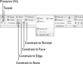
Preserve UVs
UV coordinates define how a texture map is applied to an object's surface. These UV coordinates are tied closely to the surface subobject positions, so moving a subobject after a texture is applied moves the texture also. This could cause discontinuities to the texture map. The Preserve UVs option lets you make subobject changes without altering the UV coordinates for an existing texture.
The caddy for the Preserve UVs option lets you select a Vertex Color and Texture Channel to preserve. Beneath the Preserve UVs button in the Edit panel is a Tweak button. This button lets you move the UVs for the given object. The value beneath this button is the map channel that you can adjust.
Repeat Last
The Repeat button in the Edit panel repeats the last subobject command. This button does not work on all features, but it's very convenient for certain actions.
Enabling constraints
The Constraints options limit the movement of subobjects to a specified subobject. The available constraints are None, Edge, Face, and Normal. For example, if you select and move a vertex with the Edge constraint enabled, the movement is constrained to the adjacent edges.
Slicing and cutting options
The QSlice button lets you click anywhere on an Editable Poly object where you want a slicing line to be located. You can then move the mouse, and the QuickSlice line rotates about the point you clicked. When you click the mouse again, a new vertex is added at every place where the QuickSlice line intersects an object edge. This is a very convenient tool for slicing objects because the slice line follows the surface of the object, so you can see exactly where the slice will take place.
For the QuickSlice and Cut tools, you can enable the Full Interactivity option (located near the bottom of the Polygon Modeling panel). With this option enabled, the slice lines are shown as you move the mouse about the surface. With Full Interactivity disabled, the resulting lines are shown only when the mouse is clicked.
Beneath the QSlice tool is the Cut tool. The Cut button is interactive. If you click a polygon corner, the cut edge snaps to the corner, and a new edge extends from the corner to a nearby corner. As you move the mouse around, the edge moves until you click where the edge should end. If you click in the middle of an edge or face, new edges appear to the nearest corner.
Another way to slice an object is with the SwiftLoop button. This button lets you click any open space between edges to add a loop between the adjacent edges. Once placed, you can drag to slide the loop to its actual location.
Another handy Ribbon tool for cutting holes is PConnect, which stands for Paint Connect. This tool lets you paint the location of a hole on the surface. As you paint, every edge that you cross is marked, and new edges are created between adjacent marks. By holding down the Shift key, you can make the connections happen in the middle of each edge. Holding down the Ctrl key lets you paint new edges between adjacent vertices. Clicking on a vertex with the Alt key held down removes the vertex, and the Ctrl+Alt keys together removes an edge. The Ctrl+Shift key is used to remove an entire edge loop, and the Shift+Alt keys are used to paint two parallel lines between edges.
Tip
Help videos are available for some tools, such as PConnect. These videos are located in the tooltips for the tool and appear when you hold the mouse over the tool.
NURMS
The Edit panel also includes a NURMS button. NURMS stands for Non-Uniform Rational MeshSmooth. It produces similar results to the MSmooth button, but offers control over how aggressively the smoothing is applied; the settings can be different for the viewports and the renderer. When NURMS is enabled, the Use NURMS panel, shown in Figure 14.10, appears.
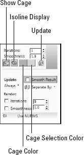
To enable NURMS subdivision, you need to enable the Use NURMS Subdivision option. The Smooth Result option places all polygons into the same smoothing group and applies the MeshSmooth to the entire object. Applying NURMS with a high Iterations value results in a very dense mesh, but the Isoline Display option displays a simplified number of edges, making the object easier to work with. The process of smoothing adds many edges to the object, and the Isoline Display option displays only the isolines. The Show Cage option makes the surrounding cage visible or invisible. The two color swatches to the right of the Show Cage option let you set the color of the cage and the selection.
The Iterations value determines how aggressive the smoothing is. The higher the Iterations value, the more time it takes to compute and the more complex the resulting object. The Smoothness value determines how sharp a corner must be before adding extra faces to smooth it. A value of 0 does not smooth any corners, and a maximum value of 1.0 smoothes all polygons.
FIGURE 14.10 The Ribbon's Use NURMS panel includes controls for NURMS subdivision.
Caution
Each smoothing iteration quadruples the number of faces. If you raise the number of Iterations too high, the system can become unstable quickly.
The two check boxes in the Render section can be used to set the values differently for the Display and Render sections. If disabled, then both the viewports and the renderer use the same settings. The smoothing algorithm can be set to ignore smoothing across Smoothing Groups and Materials.
If the Show Cage option is enabled (at the bottom of the Use NURMS panel), an orange cage surrounds the NURMS object and shows the position of the polygon faces that exist if NURMS is disabled. This cage makes selecting the polygon faces easier.
Tutorial: Smoothing an Ice Cube
NURMS can give a general smoothing to an object, which is just what we need to build an ice cube.
To create an ice cube, follow these steps:
- Use the Create Standard Primitives Box menu and drag in the viewport to create a rectangular-shaped box object.
- Open the Graphite Modeling Tools by clicking its button in the main toolbar. Then select the Convert to Poly option from the Polygon Modeling panel in the Ribbon.
- Select the Vertex subobject mode and drag over the lower four vertices. Then drag inward with the Scale tool to make the base of the box smaller than the top.
- Select the Edges subobject mode and drag over all the edges of the box object, and then Shift+click on the Chamfer button in the Edges panel to open the Chamfer caddy. Enter the value of 1 for the Chamfer Amount and the Edge Segments, and click the Ok button to apply the settings.
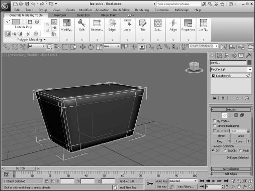
- In the Edit panel, click the NURMS button and set the Iterations value in the Use NURMS panel to 1. This smoothes all the selected edges, as shown in Figure 14.11.
FIGURE 14.11 A simple ice cube made smooth with the NURMS feature.
Relax
The Relax button works just like the Relax modifier by moving vertices so they are as far as possible from their adjacent vertices according to the Amount value listed in the pop-up caddy. The caddy also includes an Iterations value, which determines the number of times the operation is performed. You also can select to hold all Boundary and Outer points from being moved.
Create
The Create button lets you create new subobjects, specifically polygons, by connecting isolated vertices and border vertices. When the cursor is over a valid vertex, it changes to a cross-hair, and you can click to create a polygon edge from the last clicked point. If no vertices are available, you can Shift-click to create one. This creates a vertex where you click. Be aware that creating a vertex doesn't add it to any of the edges, but the Create button in Edge subobject mode can connect edges to these isolated vertices.
Tip
As you create new polygons, the normal is determined by the direction in which you create the polygon using the right-hand rule. If you bend the fingers of your right hand in the direction (clockwise or counterclockwise) that the vertices are clicked, then your thumb will point in the direction of the normal. If the normal is pointing away from you, then the backside of the polygon will be visible and the lighting could be off.
You can use the Create button to create new polygons based on new or existing vertices. To create a new face, click the Create button, which highlights all vertices in the selected mesh. Next, click a vertex to start the polygon; after you click two more vertices, a new face is created. You can also create a new vertex not based on any existing vertices by holding down the Shift key while clicking.
Polygons aren't limited to three vertices. You can click as many times as you want to add additional vertices to the polygon. Click the first vertex, or double-click to complete the polygon.
Attach
The Attach button is available with all subobject modes, even when you are not in subobject mode. Use the Attach button to add objects to the current Editable Poly object. You can add primitives, splines, patch objects, and other mesh objects. Any object attached to a mesh object is automatically converted into an editable poly and inherits the object color of the object to which it is attached. Any objects added to a poly object can be selected individually using the Element subobject mode.
Caution
If you attach an object that is smoothed using NURMS, the NURMS are lost when the object is attached.
To use this feature, select the main object and click the Attach button. Move the mouse over the object to be attached; the cursor changes over acceptable objects. Click the object to select it. Click the Attach button again or right-click in the viewport to exit Attach mode.
Note
If the object that you click to attach already has a material applied that is different from the current Editable Poly object, then a dialog box appears giving you options to Match Material IDs to Material, Match Material to Material IDs, or Do Not Modify Material IDs or Material. Materials and Material IDs are discussed in more detail in Chapter 15, “Using the Slate Material Editor.”
Selecting the Attach From List option opens the Attach List dialog box (which looks just like the Select Objects [H] dialog box) where you can select from a list of all the objects to attach. The list contains only objects that you can attach.
Note
When you enter a subobject mode, the Attach List button changes to a Detach button for poly objects.
Attaching objects is different from grouping objects because all attached objects act as a single object with the same object color, name, and transforms. You can access individual attached objects using the Element subobject mode.
Quadrify All
The Ribbon's Geometry (All) panel also includes a Quadrify All tool in the pop-up section of the panel, for converting triangles to quads. You have options to Quadrify All, Quadrify Selection, Select Edges from All, and Select Edges from Selection. This is an awesome tool if you like to work with edge loops and edge rings.
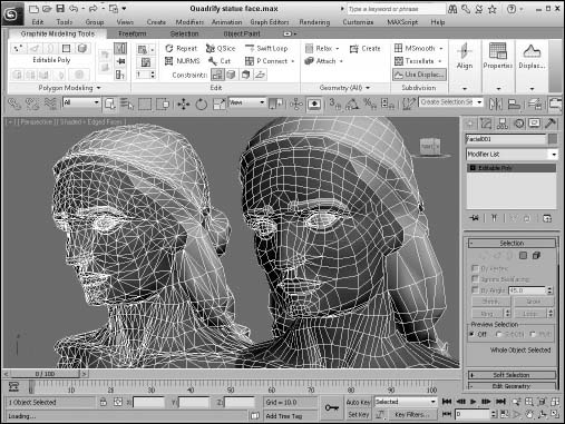
Figure 14.12 shows a face model that has been built using triangular faces on the left. Using the Quadrify All command, the face on the right is aligned to much neater rows and columns of four-sided polys. This allows the edge loop features to be used.
FIGURE 14.12 The Quadrify All command greatly simplifies this model, making it easier to work with.
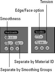
MSmooth and Tessellate Within the Subdivision panel are buttons for smoothing and tessellating the object. Both the MSmooth and Tessellate buttons include caddies, as shown in Figure 14.13. The MSmooth setting for Smoothness rounds all the sharp edges of an object. Tessellation can be done using Edges or Faces, and the Tension setting controls how tight the adjacent faces are.
FIGURE 14.13 The caddies for the MSmooth and Tessellate buttons let you interactively set the Smoothness and Tension values.
The MSmooth button can be used to smooth the selected subobjects in the same way as the MeshSmooth modifier. This button can be used several times. The Smoothness value determines which vertices are used to smooth the object. The higher the value, the more vertices are included and the smoother the result. You can also select that the smoothing is separated by Smoothing Groups or by Materials.
Tessellation is used to increase the density of the faces or edges. When modeling, you may want more details in a select area. This is where the tessellation command comes in. Tessellation can be applied to individual selected subobjects or to the entire object.
You can use the Tessellate button to increase the resolution of a mesh by splitting a face or polygon into several faces or polygons. You have two options to do this: Edge and Face.
The Edge method splits each edge at its midpoint. For example, a triangular face would be split into three smaller triangles. The Tension spinner to the right of the Tessellate button specifies a value that is used to make the tessellated face concave or convex.
The Face option creates a vertex in the center of the face and also creates three new edges, which extend from the center vertex to each original vertex. For a square polygon, this option would create six new triangular faces. (Remember, a square polygon is actually composed of two triangular faces.)
Use Displacement
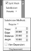
The Use Displacement tool opens the Subdivision panel, shown in Figure 14.14, when enabled. Using this panel, you can specify the subdivision method that is used and the settings for the displacement.
Cross-Reference
You can learn more about using displacement maps in Chapter 18, “Creating Compound Materials and Using Material Modifiers.”
FIGURE 14.14 The Subdivision panel includes all the subdivision settings.
Alignment options
A single vertex or two vertices don't define a plane, but three or more vertices do. If three or more vertices are selected, you can use the Make Planar button to make these vertices coplanar (which means that all vertices are on the same plane). Doing so positions the selected vertices so that they lie in the same plane. This is helpful if you want to build a new polygon face. Polygonal faces need to be coplanar. This button works in all subobject modes. The X, Y, and Z buttons let you collapse the current object or subobject selection to a single plane lying on the specified axis.
The View and Grid Align buttons move and orient all selected vertices to the current active viewport or to the current construction grid. These buttons can also be used in all subobject modes. This causes all the selected face normals to point directly at the grid or view.
Editing Vertex subobjects
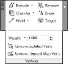
When working with the Editable Poly objects, after you select a Vertex subobject mode (keyboard shortcut, 1) and select vertices, you can transform them using the transform buttons on the main toolbar. All vertex-specific commands are found within the Vertices panel, shown in Figure 14.15, but some new tools also appear in the Geometry (All) panel including Collapse, Detach, and Cap Poly.
FIGURE 14.15 When the Vertex subobject mode is selected, these vertex commands become available.
Collapse
The Collapse button is used to collapse all the selected subobjects to a single subobject located at the averaged center of the selection. This button is similar to the Weld button, except that the selected vertices don't need to be within a Threshold value to be combined. This button works in all subobject modes.
Detach
Use the Detach button to separate the selected subobjects from the rest of the object. To use this button, select the subobject and click the Detach button. The Detach dialog box opens, enabling you to name the new detached subobject. You also have the options to Detach to Element or to Detach as Clone. All subobject modes except Edge have a Detach option.
Extrude
The Extrude button copies and moves the selected subobject perpendicular a given distance and connects the new copy with the original one. For example, four edges forming a square extruded would form a box with no lid. To use this feature, select an edge or edges, click the Extrude button, and then drag in a viewport. The edges interactively show the extrude depth. Release the button when you've reached the desired distance.
Alternatively, you can set an extrude depth in the Extrusion spinner in the caddy. The Group option extrudes all selected edges in the direction of the average of all the normals for the group (the normal runs perpendicular to the face), and the Normal Local option moves each individual edge along its local normal. For polygons, you can extrude By Polygons, which extrudes each individual polygon along its normal as a separate extrusion. To exit Extrude mode, click the Extrude button again or right-click in the viewport.
The Extrude button is enabled for Face, Polygon, and Element subobject modes for the Editable Poly object. The Local Normal option extrudes each edge along its own normal.
The Extrude settings caddy includes options for setting the Extrusion Height and the Extrusion Base Width.
Remove
The Remove button lets you delete the selected vertices. The Remove button automatically adjusts the surrounding subobjects to maintain the mesh integrity.
Note
You can also delete Editable Poly subobjects using the Delete key.
The Remove button also is available in Edge subobject mode. If you hold down the Ctrl key when clicking the Remove button when an edge is selected, vertices at either end of the deleted edge are also removed.
Break
You use the Break button to create a separate vertex for adjoining faces that are connected by a single vertex.
In a normal mesh, faces are all connected by vertices: Moving one vertex changes the position of all adjoining faces. The Break button enables you to move the vertex associated with each face independent of the others. The button is available only in Vertex subobject mode.
Chamfer and Weld
The Chamfer button—which is enabled in Vertex, Edge, and Border subobject modes—lets you cut the edge off a corner and replace it with a face. Using the Chamfer caddy, you can interactively specify a Chamfer Amount and the number of segments. The caddy also includes an Open option, which cuts a hole in the polygon face instead of replacing it with a new polygon.
Vertices and edges that are close or on top of one another can be combined together into one using the Weld command. The Weld and Chamfer buttons include caddies that let you interactively see the results of different settings. The Weld caddy includes a weld Threshold value and displays the number of vertices before and after the welding process, which is very useful to check whether a weld was successful.
The Target button lets you click a single vertex and move the cursor over an adjacent vertex. A rubber band line stretches from the first selected vertex to the target weld vertex, and the cursor changes to indicate that the vertex under the cursor may be selected. Clicking the target vertex welds the two vertices together.
Note
When two vertices are welded, the new vertex is positioned at a location that is halfway between both vertices, but when Target Weld is used, the first vertex is moved to the location of the second.
Weight and Crease
The Weight settings control the amount of pull that a vertex has when NURMS subdivision or a MeshSmooth modifier is used. The higher the Weight value, the more resistant a vertex is to smoothing. For edge and border subobjects, the Weight value is followed by a Crease value that determines how visible the edge is when the mesh is smoothed. A value of 1.0 ensures that the crease is visible.
Remove Isolated and Unused Map Vertices
The Remove Isolated Vertices button deletes all isolated vertices. Vertices become isolated by some operations and add unneeded data to your file. You can search and delete them quickly with this button. Good examples of isolated vertices are those created using the Create button but never attached to an edge.
The Remove Unused Map Vertices button removes any leftover mapping vertices from the object.
Editing Edge and Border subobjects
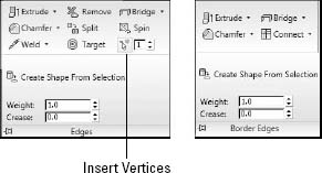
All the edge editing tools are located in the Edges and Borders panels, shown in Figure 14.16. Many of the Edge subobject options work in the same way as the Vertex subobject options.
FIGURE 14.16 All the Edge specific commands are available when the Edge subobject mode is enabled. Many of the Border subobject commands are the same as those for Edges.
Bridge Edges
The Bridge button for edges allows you to create a new set of polygons that connect the selected edges. If two edges are selected when the Bridge button is pressed, then they are automatically connected with a new polygon. If no edges are selected, then you can click the edges to bridge after clicking the Bridge button. The selected edges on either side of the bridge can be different in number.
You also can access the caddy for the Bridge feature. This caddy offers the options to Bridge Specific Edges or to Use Edge Selection. The Bridge Specific Edges option has two buttons for each edge. If you click one of these buttons, you can select an edge in the viewport. The Use Edge Selection option lets you drag a marquee in the viewport to select the edges. The Bridge Edges caddy also includes options for setting the number of Segments, the Smooth value, and a Bridge Adjacent value, which increases the triangulation for angles above the given threshold.
Split and Insert Vertex
The Split button adds a new vertex at the middle of the edge and splits the edge into two equal sections. This button is handy when you need to increase the resolution of a section quickly.
The Insert Vertex button lets you add a new vertex anywhere along an edge. The cursor changes to cross-hairs when it is over an edge. Click to create a vertex. When in Edge, Border, Polygon, or Element subobject mode, this button also makes vertices visible. Within the Ribbon's Edges pane, you can set the number of vertices to be placed evenly along the selected edges using the number spinner next to the Insert Vertices tool.
Create Shape from Selection
The Create Shape from Selection button creates a new spline shape from selected edges. You can also select options for Smooth or Linear shape types.
Spin
The Spin button rotates the hidden edges that break up the polygon into triangles (all polygonal faces include these hidden edges). For example, if a quadrilateral (four-sided) face has a hidden edge that runs between vertices 1 and 3, then the Spin button changes this hidden edge to run between vertices 2 and 4. This affects how the surface is smoothed when the polygon is not coplanar.
Cap Poly
The Cap Poly button that appears in the Geometry (All) panel causes the existing border selection to be filled in with a single coplanar polygon. After using this feature, the Border subobject is no longer identified as a Border subobject.
Bridge
The Bridge feature joins two selected Border subobjects with a tube of polygons that connect the two borders. The two selected borders must be part of the same object and need not have an equal number of segments.
Editing Polygon and Element subobjects
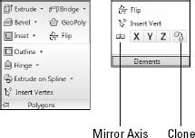
Like the other subobject modes, Editable Polys can be edited at the polygon and element subobject level. The buttons for these modes are found in the Polygons and Elements panels. Figure 14.17 shows the Ribbon's Polygons and Elements panels.
FIGURE 14.17 The Polygon and Element subobjects commands are found in the Polygons and Elements panels.
Bevel
The Bevel button extrudes the Polygon subobject selection and then lets you bevel the edges. To use this feature, select a polygon, click the Bevel button, drag up or down in a viewport to the Extrusion depth, and release the button. Drag again to specify the Bevel amount. The Bevel amount determines the relative size of the extruded face.
GeoPoly
The GeoPoly button moves the vertices of the selected polygon to make a regular polygon whose vertices are all equally spaced. The shape of the resulting polygon depends on the number of vertices included in the polygon face.
Inset and Outline
The Outline button offsets the selected polygon a specified amount. This increases the size of the selected polygon or element. The Inset button creates another polygon set within the selected polygon and connects their edges. For both these buttons, a caddy is available that includes the Outline or Inset Amount values.
Flip
The Flip button flips the normal vectors for the selected subobjects. The Flip button is available only in Polygon and Element subobject modes.
Hinge
The Hinge button rotates a selected polygon as if one of its edges were a hinge. The angle of the hinge depends on the distance that you drag with the mouse, or you can use the available caddy. By default, one of the polygon's edges will be used as the hinge about which the section rotates, but in the caddy, you can click the Pick Hinge button and select an edge (which doesn't need to be attached to the polygon).
Extrude Along Spline
The Extrude on Spline button can be used to extrude a selected polygon along the spline path. The caddy includes a Pick Spline button that you can use to select the spline to use. You can also specify the number of segments, the Taper Amount and Curve, and a Twist value. You also have an option to Align the extrusion to the face normal or to rotate about the normal.
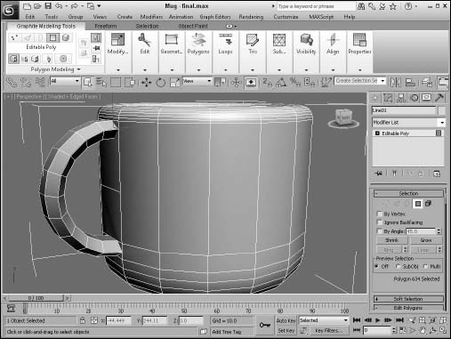
Tutorial: Adding a handle to a mug
Creating a cup is fairly easy using the Lathe modifier, but adding the handle is another story. It could be created as half a torus and Boolean connected to the cup, but this example shows how to use the poly modeling features to hinge the handle on.
To add a handle to a mug, follow these steps:
- Open the Mug.max file from the Chap 14 directory on the CD.
This file includes a simple cup created using the Lathe modifier, and it has been converted to an Editable Poly object. Open the Graphite Modeling Tools by clicking on its button in the main toolbar.
- Select the QSlice button Edit panel and click in the Front viewport about one-third up from the bottom of the cup, then orient the line to be horizontal and click again.
- Click on the Cut button in the Edit panel and cut edges into each corner of one of the polygon faces near the bottom of the cup. Then cut another horizontal edge in the middle of the cup. Right-click in the viewport to exit the Cut tool.
- Select the Polygon subobject mode in the Polygon Modeling panel and click on the interior of the cut polygon just created. Shift-click on the Hinge button in the Polygons panel. In the Hinge From Edge caddy, click the Pick Hinge button and click on the midline edge that was cut, set the Segments to 10, and the Angle to 185, then click on the Ok button.
Figure 14.18 shows the resulting handle on the mug. You can add a NURMS command to smooth the mug handle.
Mirroring elements
Within the Elements panel are commands for mirroring the current selection about the X, Y, or Z axes. These commands move the element to the opposite side, but clicking the Clone button creates a clone of the selected element.
FIGURE 14.18 The handle for this mug was created with the Hinge feature.
Surface properties
In the Properties panel are several settings for additional properties such as vertex colors, material IDs, and Smoothing Groups.
Vertex Surface properties
The Vertex Properties panel in Vertex subobject mode lets you define the Color, Illumination, and Alpha value of object vertices. The color swatches enable you to select Color and Illumination colors for the selected vertices. The Alpha value sets the amount of transparency for the vertices. After you assign colors, you can then recall vertices with the same color by selecting a color (or illumination color) in the Select Vertices By section and clicking the Select button. The RGB (red, green, and blue) values match all colors within the Range defined by these values.
Cross-Reference
You can find more information on vertex colors in Chapter 32, “Painting in the Viewport Canvas and Rendering Surface Maps.”
Polygon and Element Surface properties
For Polygon and Element subobjects, the Properties panel, shown in Figure 14.19, includes Material IDs and Smoothing Groups options. The Material IDs option settings are used by the Multi/Sub-Object material type to apply different materials to faces or polygons within an object. By selecting a polygon subobject, you can use these option settings to apply a unique material to the selected polygon. The Select ID button selects all subobjects that have the designated Material ID, or you can select subobjects using a material name in the drop-down list under the Select ID button.
Cross-Reference
You can find more information on the Multi/Sub-Object material type in Chapter 16, “Creating and Applying Standard Materials.”
FIGURE 14.19 The Properties panel includes settings for Material IDs, Smoothing Groups, and Vertex Colors.
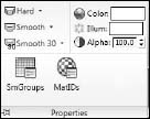
You use the Smoothing Groups option to assign a subobject to a unique smoothing group. To do this, select a subobject and click a Smoothing Groups number. The Select By SG button, like the Select By ID button, opens a dialog box where you can enter a Smoothing Groups number, and all subobjects with that number are selected. The Clear All button clears all Smoothing Groups number assignments, and the Auto Smooth button automatically assigns Smoothing Groups numbers based on the angle between faces as set by the value to the right of the Auto Smooth button.
The Properties panel also includes options for setting vertex Color, Illumination, and Alpha values.
Using the Freeform Tools
The middle tab in the Graphite Modeling tools includes an assortment of Freeform tools for sculpting and modeling surfaces as if working with clay. These tools are divided into three panels—PolyDraw, Paint Deform, and Defaults. The PolyDraw panel is shown in Figure 14.20.
FIGURE 14.20 The Freeform tools let you model by sculpting.
Using the PolyDraw tools
The various PolyDraw tools let you create and extend the surface subobjects using tools that work like a common drawing program.
Drag
The Drag tool lets you move selected subobjects around by simply dragging them with the mouse. Clicking a subobject automatically selects it and lets you drag it to a new position. Holding down the Shift key or the Ctrl key lets you drag edges or polygons regardless of the subobject mode that is selected. Pressing Shift+Ctrl keys together lets you drag entire edge loops, and the Alt key lets you move the subobject in a direction that is perpendicular to the view axis, which is great for dragging subobjects off to the side of an object.
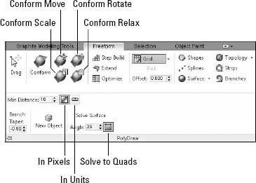
Conform
The Conform brushes let you push all the vertices of the selected object toward a selected underlying object. When the Freeform panel is first accessed, you can select the Draw On: Surface option to the right of the Step Build button. When Surface is selected, the Pick button becomes active. Using this button, you can select the object to which you want the selected object to be conformed.
New Feature
The Conform brushes are new to 3ds Max 2012.
With the object to conform to selected, you can select the Conform button and change the options for this brush using the Conform panel, shown in Figure 14.21. Within the Conform panel, you can set the Strength, Falloff, and Conform values. The Conform value sets the rate at which the vertices move toward the conform object. Higher values make the vertices move immediately, and smaller values, such as 0.1, cause the movement to be gradual.
FIGURE 14.21 The Conform panel holds the options for using the Conform brushes.
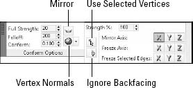
The Mirror option causes the vertices’ movement to be applied equally on either side of the mirror axis. The Vertex Normals/View drop-down list lets you control how the vertices move. The View option causes the vertices to move toward the target into the current view, and the Vertex Normals option moves the vertices along their normals toward the conform object. You also have options to move only the selected vertices, to Ignore Backfacing vertices, to select the mirror and freeze axes, and to freeze specific selected edges so no movement happens.
Within the PolyDraw panel are four brushes for defining how the vertices are transformed. The Conform Move brush moves vertices under its brush range. Vertices also can be rotated and scaled using the Conform Rotate and Conform Scale brushes, and the Conform Relax brush smoothes the moved vertices by moving them gradually toward their original position.
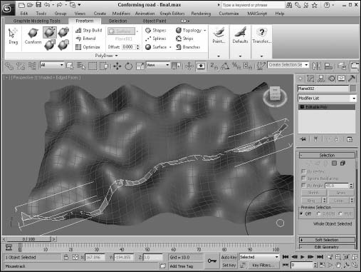
Tutorial: Matching a road to a rolling terrain
If you've created a rough rolling landscape using a Plane object and the Noise modifier, matching a road running across the surface can be tricky if you have to select and move each individual vertex. Instead, you can use the Conform brushes to move the vertices so they match the underlying hills.
To conform a road to an underlying terrain, follow these steps:
- Open the Conforming road.max file from the Chap 14 directory on the CD.
- With the road selected, click the Graphite Modeling Tools button on the main toolbar to make the Ribbon appear, and select the Freeform tab.
- Select the Draw On: Surface option from the drop-down list to the right of the Step Build button, click the Pick button, and click the hilly object. Then select the straight road object, and click the Conform button.
- In the Conform panel, select the View option and change the viewport to the Top view.
- Select the Conform Move brush, and click and slowly rotate the brush in small circles over the road object to move its vertices to conform to the hilly landscape, as shown in Figure 14.22.
FIGURE 14.22 The Conform Move brush is used to make the road match the underlying terrain.
Step Build
The Step Build tool lets you click to place new vertices on the surface of the object. The location of these new vertices depends on the current Grid, on the current object's Surface, or within the Selection using the On selections located to the right of the Step Build button. If you select the On: Surface option, then you can use the Pick button to select the object whose surface you want to create vertices on. After freestanding vertices are created, you can hold down the Shift key and drag over these new vertices to create a polygon. The Ctrl key lets you remove polygons, and the Alt key lets you remove vertices. With these controls, you can quickly remove and rebuild polygons to create new shapes.
Extend
The Extend tool works on border subobjects and lets you add new polygons to fill the hole by dragging on the border vertices. If you press and hold the Shift key while dragging an edge, you can pull the edge away to create a new polygon. Dragging with the Shift+Ctrl keys lets you drag two adjacent edges out. The Ctrl key and a click deletes the polygon, and dragging with the Alt key held down moves the polygon perpendicular to the view axis.
Optimize
The Optimize tool quickly collapses subobjects. Click an edge with this tool to remove it and to combine its two end points into one. The Shift key is used to target weld two vertices into a single one, and the Alt key removes vertices. The Shift+Ctrl key combo can remove an entire edge loop at once.
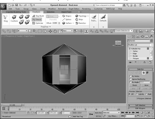
Tutorial: Opening a diamond
Ever wonder what was inside a diamond? This example uses some of the PolyDraw tools to open up a diamond. Maybe there is treasure inside!
To edit a diamond-shaped object, follow these steps:
- Select Create Standard Primitives Sphere, and drag in the Top viewport to create a Sphere object. Set its Segments value to 6. Then right-click, and select Convert To Editable Poly from the pop-up quadmenu.
- Open the Graphite Modeling tools, click the Freeform tab, select the Step Build tool, press and hold the Ctrl key, and click the center polygon to delete the polygon. Then click within the center polygon to create four vertices in the shape of a square. Then press and hold the Shift key, and drag near these vertices to create a polygon.
- Select the Drag tool, and drag the new vertices until they are aligned with each other to form a square.
- Select the Extend tool, and with the Shift key pressed, drag the edge on the left side of the open polygon toward the middle to create a new extended polygon. Then repeat for the left side.
Figure 14.23 shows the resulting diamond.
FIGURE 14.23 The PolyDraw tools let you work quickly to add, remove, and rebuild polygons.
Draw On and Pick
The Draw On drop-down list gives you three options for specifying the object that is drawn on: Grid, Surface, and Selection. If Surface is selected, you can use the Pick button to choose the surface object. You also can set an Offset, which is the distance above the surface on which the drawn objects appear.
Tip
It is best to keep a non-zero offset value when drawing on the surface of an object, especially if the drawn object overlaps an edge. This keeps the surfaces from interpenetrating.
Shapes and Solve Surface
The Shapes tool lets you draw polygonal shapes directly on the surface of an object. Figure 14.24 shows three polygons drawn on the surface of a torus. You also can delete drawn polygons with the Ctrl key. The completed polygons likely will have multiple vertices, but you can reduce the polygons to tris and quads using the Solve Surface button.
FIGURE 14.24 Using the Shapes tool, you can draw polygons that conform to the surface of the underlying object.

Splines
The Splines tool lets you draw spline objects that follow the surface of the underlying object. The Ctrl key can be used to delete drawn splines.
Surface, Topology, Strips, and Branches
The Surface tool covers the object with a mesh of quads by painting over the object. You can delete any polygon by clicking it with Ctrl key held down. The Topology tool lets you draw a series of parallel lines followed by a set of perpendicular lines to form quads. The Auto Weld option automatically welds vertices together to form a mesh. The Ctrl key extends a line from the nearest end point.
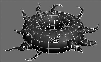
The Strips tool draws a consecutive row of quads that flow across the surface of the object. The Shift key extends the strip from the nearest edge. The Branches tool extends a tapered branch from a single polygon. For the branches, you can set a Taper amount; the Minimum Distance value sets the distance between the segments. This is useful for creating tentacles, as shown in Figure 14.25.
FIGURE 14.25 Using the Branches tool, you can drag out extending arms from polygons.
Using the Paint Deform tools
The Paint Deform tools let you sculpt the surface of an object by pushing, pulling, and modeling the object in organic ways like it was clay. Whenever any of the tools on the Paint Deform panel, shown in Figure 14.26, are selected, its settings for the brush's Size and Strength (and sometimes Offset, depending on the tool) appear in the Paint Options panel to the side of the Paint Deform panel.
FIGURE 14.26 The Paint Deform tools are used to sculpt an object's surface with gradual changes.
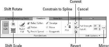
Shift/Shift Rotate/Shift Scale
The Shift tool lets you drag all subobjects within the brush radius, and all subobjects within the falloff radius are moved to a less extent. You can control the brush size and falloff in the Options panel, or you can press and hold the Ctrl key and drag to alter the brush's radius. The Shift+drag changes the brush's falloff indicated by the inner white circle.
The Shift Rotate and Shift Scale brushes are used to rotate and/or scale all the vertices within the brush's range.
New Feature
The Shift Rotate and Shift Scale brushes are new to 3ds Max 2012.
Push/Pull
The Push/Pull tool also has Size and Strength values, but it is different in that the brush follows the surface of the object. Dragging over an area pulls the vertices within the brush's radius outward, and holding down the Ctrl key pushes the vertices inward. The Shift key relaxes the area under the brush.
Relax/Soften
The Relax/Soften brush removes any extreme changes in the surface such as hard edges of a cube. The Alt key lets you relax the surface without changing its volume, and the Ctrl key causes the surface to revert to its previous state.
Flatten and Pinch/Spread
The Flatten brush pulls any bends out of the mesh causing the object to be working into a flat plane. The Ctrl key causes the object to revert to its previous state, and the Shift key accesses the Relax/Soften brush. The Pinch/Spread tool causes vertices to be pulled in closer to each other, and holding down the Alt key has the opposite effect and pushes them away.
Smudge, Noise, and Exaggerate
The Smudge tool pushes the surrounding vertices away from the center of the brush. Dragging over the same vertices multiple times moves them each time. Holding down the Alt key causes the vertices to be moved only along the surface and not to be moved along the normal. The Noise tool randomly moves the vertices about to create a random noise pattern. The Exaggerate tool pushes vertices farther in the current direction to emphasize the details.
Constrain to Spline
If you want more control over the precise surface area that is changed using the Paint Deform tools, you can select the Constrain to Spline option and use the Pick button to select a spline near the surface area to change.
New Feature
The Constrain to Spline feature is new to 3ds Max 2012.
Revert
At any point, you can use the Revert tool to gradually change the object back to its last saved point. You can set a save point by clicking the Commit button, which looks like a green check mark. The Cancel button (a red X) removes the recent changes from the object.
Using the Selection Tools
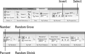
The next tab offers several additional Selection tools. These tools make it possible to locate specific subobjects by looking for certain criteria such as concavity, normals, and symmetry. Figure 14.27 shows the panels for this tab.
FIGURE 14.27 The Selection tab includes panels for selecting specific subobject selections.
Selecting Tops, Open, and Non-Quads
The first three tools in the Selection tab are the Tops, Open, and Non-Quads tools. The Tops tool selects all vertices resulting from the extruded sections. This quickly lets you grab all extended sections and extend or reduce them as needed. The Open tool selects all open borders, and the Non-Quads tool finds all polygons that consist of trios or more than four corners. This is a valuable tool when working with edge loops.
Note
The Non-Quads option is only available when the Polygon or Element subobject mode is selected.
Copying and pasting selections
The Stored Selection panel lets you copy a selection of subobjects into two available stores. These copied selections can be restored at any time by clicking the Paste button. Additional buttons let you combine the two selection stores, subtracting one from another and getting only the intersecting selection between the two. The Clear button removes the selection from the store.
The Copy and Paste Sets buttons let you copy a selection set from the main toolbar and paste it as needed.
Selecting by criteria
The remaining selection criteria let you locate subobjects using a variety of different methods.
By Surface, Normal, and Perspective
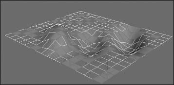
The By Surface panel lets you specify a degree of concavity, and the tool locates all the concave areas in the current object. Negative values also can be used to find convex regions. Figure 14.28 shows the selected concave regions.
FIGURE 14.28 The By Surface tool can be used to find the concave regions of an object.
The By Normal panel lets you choose an axis and a value, and all subobjects within the Angle value for the selected axis are selected. This is a great way to quickly determine which polygons are facing away from the current view. The Invert button can find all normals pointing toward the negative axis side.
The By Perspective panel selects those polygons that are within the Angle value to the view axis. If the Outline button is enabled, then only the outer borders of polygons are selected. Click the Select button to see all the selected polygons meeting the criteria.
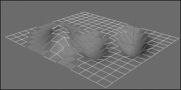
By Random, Half, and Pivot Distance
The By Random panel lets you randomly select polygons within the current object. You can set to randomly select a given number or a percentage of the total. The Select button makes the random selection, or you can randomly select within the current selection. Additional buttons grow or shrink the selection. Figure 14.29 shows a random selection.
The By Half panel lets you quickly choose half of the available polygons as determined by axis. The Invert Axis button lets you choose the negative side of the axis. The By Pivot Distance chooses those polygons that are farthest away from the current pivot point, creating a circular selection area. Reducing the distance value creeps the selection closer to the pivot's location.
FIGURE 14.29 The By Random tool can be used to make a random selection of polygons.
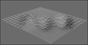
By View, Symmetry, and Numeric
The By View panel selects those polygons closest to the current view camera. Increasing this value extends the selection farther into the scene, as shown in Figure 14.30.
FIGURE 14.30 The By View tool is used to select those polygons closest to the current view.
Regardless of the current selection, you can make it symmetrical about any of the three axes using the By Symmetry panel. The By Numeric panel, which is only available in Vertex and Polygon modes, lets you select all vertices that have a given number of edges or polygons that have a given number of sides. The Equal, Less Than, and Greater Than buttons are used to mathematically determine those subobjects.
By Color
The By Color panel, available in Vertex mode, lets you locate any vertices that have a given color or Illuminate vertex color setting according to the specified RGB values.
Using the Object Paint Tools
The last tab is the Object Paint tab. This tab includes tools that let you select and paint with a specific object. This is great for spreading objects around a scene. The tab also includes several options for randomizing the size, orientation, and placement of the painted objects.
Selecting an object to paint with
Within the Paint Objects panel, shown in Figure 14.31, are two paint modes for painting and filling. Each of these buttons is a toggle and turns the paint mode on and off. While each mode is active, you can switch between objects and subobjects as needed.
FIGURE 14.31 The Paint Objects panel lets you paint or fill with objects.

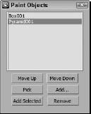
Before you can begin painting with an object, you need to select an object using the Pick Object button. Simply click the Pick Object button and select an object in the scene. The selected object is highlighted and added to the list of paint objects. If you select the Pick Object button again, you can add another object to the list of paint objects. Clicking the Edit Object List button opens the list of current paint objects, as shown in Figure 14.32. Using this list, you can change the order of the items, pick new items, add items using the Select Objects dialog box, add the selected scene object, or remove the selected item from the list.
FIGURE 14.32 The Paint Objects list lets you manage the objects that you're painting with.
Painting with objects
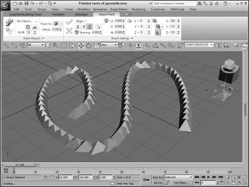
After a paint object is selected, you can click the Paint button to enable paint mode and then drag in the viewport, as shown in Figure 14.33. Each stroke drawn with the brush lays down a new curve. The Undo command can be used to remove the last stroke, but all strokes are not added to the scene until the Commit button in the Brush Settings panel is clicked. The Cancel button removes all strokes drawn since the last commit.
Caution
Painting with objects dramatically increases the overall polygon count of the scene, especially if you are painting with a complex object. Try to keep the paint object as simple as possible to avoid unwieldy scenes.
FIGURE 14.33 After an object is selected, simply drag in the viewport to paint with the selected object.
Before a painted set of objects is committed to the scene, you can use the settings in the Brush Settings panel, shown in Figure 14.34, to change the alignment, spacing, rotation, and scale of the objects. You have several options for randomly scattering the objects. The default alignment for the painted objects is to match the picked object, or you can align the object to the X, Y, or Z axis or flip it about the specified axis with the Flip Axis button.
FIGURE 14.34 The Brush Settings panel lets you change the position, rotation, and scale of the painted objects.
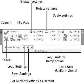
The Spacing value lets you change how far away each object is from its neighbor. The Scatter settings let you move the objects in the U, V, or W directions. The Rotation setting uniformly rotates all the objects together, or you can allow random rotations by clicking the small arrow to the right of each axis and enabling the Random option.
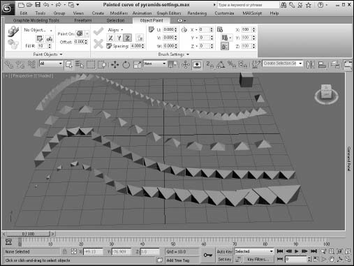
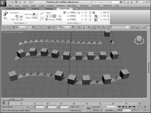
For the Scale settings, you can enable the Lock Axis (Uniform Scaling) option to scale all objects evenly or you can enable the Random option to randomly scale the objects within a set range of values. The Ramp option scales the objects gradually from the start of the stroke to the end of the stroke to a given size. Figure 14.35 shows several lines of pyramids with different settings. The top line is the default. The second line has an altered spacing value, the third line is oriented about the Y axis, and the final line uses a ramp scaling.
FIGURE 14.35 Painted objects can be altered by spacing, orientation, and scaling.
Painting with multiple objects
If you have multiple objects in the Paint Objects list, you can choose which objects to paint with using the option in the Paint Objects panel. The first option is to paint with just the most recently picked object. The second option is to paint with all objects in order, and the last option is to randomly paint with all objects. Figure 14.36 shows each of these options.
FIGURE 14.36 When painting with multiple objects, you can choose to paint the objects in order or randomly.
Painting on objects
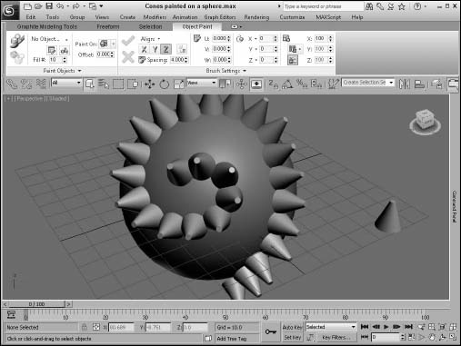
The Object Paint feature lets you paint on the default construction grid, on the selected object or on the entire scene. These options are available in the Paint Objects panel. Figure 14.37 shows painting some cones on a simple sphere. The cones are aligned by default to the surface normals of the sphere.
When the Scene option is selected, the painted objects are placed on the default grid unless a scene object is encountered, and then it is placed on top of the scene object. The Offset value can be used to move the painted objects into or off of the surface of the underlying object.
FIGURE 14.37 Objects also can be painted on the surface of another object in the scene.
Using the Paint Fill mode
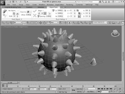
The Paint Fill mode allows you to place the paint object at regular intervals along a selected edge. Before the Paint Fill mode is enabled, you need to have a paint object selected and an edge or an edge loop selected. Once selected, the Paint Fill button simply places the paint object along the edge. The Fill Number value determines the number of objects that are placed along the selected edge loop. Figure 14.38 shows a sphere filled with several cone objects using this mode.
FIGURE 14.38 The Paint Fill mode places objects along a selected edge loop.
Painting with animated objects
If the object that you are painting with has some animation associated with it, then you can specify an offset for the motion of the object. The options for how the animated object plays are in the Paint Objects panel and include Consecutive, which plays the animation on each painted object in order offset by the By # Frames value. For example, if you have a box that spins and you set the By # Frames value to 2, then the first box in the painted line will start spinning at frame 0 and the second will start at frame 2, and so on. The other Offset Transform Motion option is Random, which randomly starts the animation for each object.
Tutorial: Painting a scar
Although medical companies are searching for an easy way to remove scars, we're going to use the Object Paint feature to add one to our character.
To add a character scar using the Object Paint feature, follow these steps:
- Open the Futureman with scar.max file from the Chap 14 directory on the CD.
- Click the Graphite Modeling Tools button on the main toolbar to make the Ribbon appear, and select the Object Paint tab.
- Click the Pick Object button in the Paint Objects panel, and then click the scar object. Select the Paint On option, and select the futureman's face object.
- Click the Paint button, and drag across futureman's face to place the scar.
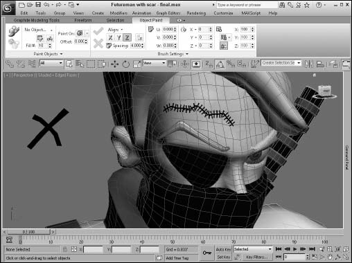
- In the Brush Settings panel, enable the Lock Axis (Uniform Scale) button, set the Scale X value to 17, and drag the Spacing value until the scar is equally spaced out at a value around 11.5. Figure 14.39 shows the applied scar.
- Click the Commit button in the Brush Settings panel to apply the scar to the face.
FIGURE 14.39 Applying scars on the surface of a character is easy with the Object Paint feature.
Summary
When modeling with polygons, the Graphite Modeling tools become your best friends. With all the tools at your fingertips, you can model faster and with greater ease. In addition to the base modeling features, the Freeform modeling tools, the Selection tools, and the Object Paint features make modeling a delight. More specifically, this chapter covered the following topics:
- Accessing and using the Graphite Modeling tools
- Modeling in the various subobject modes
- Using the Freeform tools to sculpt surfaces
- Making specific selections with the Selection tools
- Painting with objects and filling edges with the Paint Object panel
This chapter concludes Part III, “Modeling Basics.” You're now ready to learn about dressing up objects with materials, cameras, and lights. The next chapter covers the basics of applying materials.