
CHAPTER 7
Transforming Objects, Pivoting, Aligning, and Snapping
Transforming objects
Controlling transformations with the Transform Gizmos, the Transform Type-Ins, and the Transform Managers
Working with pivot points and axis constraints
Aligning objects with the align tools
Using grids and snapping objects to common points
Although a transformation sounds like something that would happen during the climax of a superhero film, transformation is simply the process of “repositioning” or changing an object's position, rotation, or scale. So moving an object from here to there is a transformation. Superman would be so envious.
Max includes several tools to help in the transformation of objects, including the Transform Gizmos, the Transform Type-In dialog box, and the Transform Managers.
This chapter covers each of these tools and several others that make transformations more automatic, such as the alignment, grid, and snap features.
Translating, Rotating, and Scaling Objects
So you have an object created, and it's just sitting there—sitting and waiting. Waiting for what? Waiting to be transformed. To be moved a little to the left or rotated around to show its good side or scaled down a little smaller. These actions are called transformations because they transform the object to a different state. Transformations are different from modifications. Modifications change the object's geometry, but transformations do not affect the object's geometry at all.
The three different types of transformations are translation (which is a fancy word for moving objects), rotation, and scaling.
Translating objects
The first transformation type is translation, or moving objects. This is identified in the various transform interfaces as the object's Position. You can move objects along any of the three axes or within the three planes. You can move objects to an absolute coordinate location or move them to a certain offset distance from their current location.
![]() To move objects, click the Select and Move button on the main toolbar (or press the W key), select the object to move, and drag the object in the viewport to the desired location. Translations are measured in the defined system units for the scene, which may be inches, centimeters, meters, and so on.
To move objects, click the Select and Move button on the main toolbar (or press the W key), select the object to move, and drag the object in the viewport to the desired location. Translations are measured in the defined system units for the scene, which may be inches, centimeters, meters, and so on.
Rotating objects
![]() Rotation is the process of spinning the object about its Transform Center point. To rotate objects, click the Select and Rotate button on the main toolbar (or press the E key), select an object to rotate, and drag it in a viewport. Rotations are measured in degrees, where 360 degrees is a full rotation.
Rotation is the process of spinning the object about its Transform Center point. To rotate objects, click the Select and Rotate button on the main toolbar (or press the E key), select an object to rotate, and drag it in a viewport. Rotations are measured in degrees, where 360 degrees is a full rotation.
Scaling objects
Scaling increases or decreases the overall size of an object. Most scaling operations are uniform, or equal in all directions. All Scaling is done about the Transform Center point.
![]() To scale objects uniformly, click the Select and Uniform Scale button on the main toolbar (or press the R key), select an object to scale, and drag it in a viewport. Scalings are measured as a percentage of the original. For example, a cube scaled to a value of 200 percent is twice as big as the original.
To scale objects uniformly, click the Select and Uniform Scale button on the main toolbar (or press the R key), select an object to scale, and drag it in a viewport. Scalings are measured as a percentage of the original. For example, a cube scaled to a value of 200 percent is twice as big as the original.
Non-uniform scaling
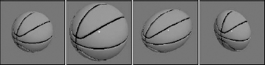
![]() The Select and Scale button includes two flyout buttons for scaling objects non-uniformly, allowing objects to be scaled unequally in different dimensions. The two additional tools are Select and Non-Uniform Scale, and Select and Squash, shown in Table 7.1. Resizing a basketball with the Select and Non-Uniform Scale tool could result in a ball that is oblong and taller than it is wide. Scaling is done about whatever axes have been constrained (or limited) using the Restrict Axes buttons on the Axis Constraints toolbar.
The Select and Scale button includes two flyout buttons for scaling objects non-uniformly, allowing objects to be scaled unequally in different dimensions. The two additional tools are Select and Non-Uniform Scale, and Select and Squash, shown in Table 7.1. Resizing a basketball with the Select and Non-Uniform Scale tool could result in a ball that is oblong and taller than it is wide. Scaling is done about whatever axes have been constrained (or limited) using the Restrict Axes buttons on the Axis Constraints toolbar.
Squashing objects
![]() The Squash option is a specialized type of non-uniform scaling. This scaling causes the constrained axis to be scaled at the same time that the opposite axes are scaled in the opposite direction. For example, if you push down on the top of a basketball by scaling the Z-axis, the sides, or the X- and Y-axes, it bulges outward. This simulates the actual results of such materials as rubber and plastic.
The Squash option is a specialized type of non-uniform scaling. This scaling causes the constrained axis to be scaled at the same time that the opposite axes are scaled in the opposite direction. For example, if you push down on the top of a basketball by scaling the Z-axis, the sides, or the X- and Y-axes, it bulges outward. This simulates the actual results of such materials as rubber and plastic.
Tip
You can cycle through the different Scaling tools by repeatedly pressing the R key.
Figure 7.1 shows a basketball that has been scaled using uniform scaling, non-uniform scaling, and squash modes.
Note
It is also important to be aware of the order of things. Transformations typically happen at the top of the stack after all object properties and modifiers are applied. More on the stack is covered in Chapter 11, “Introducing Modifiers and Using the Modifier Stack.”
FIGURE 7.1 These basketballs have been scaled using uniform, non-uniform, and squash modes.
Using the transform buttons
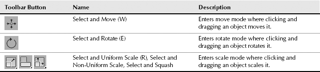
The three transform buttons located on the main toolbar are Select and Move, Select and Rotate, and Select and Uniform Scale, as shown in Table 7.1. Using these buttons, you can select objects and transform them by dragging in one of the viewports with the mouse. You can access these buttons using three of the big four keyboard shortcuts: Q for Select Objects, W for Select and Move, E for Select and Rotate, and R for Select and Uniform Scale.
Working with the Transformation Tools
To help you in your transformations, you can use several tools to transform objects (and you don't even need a phone booth). These tools include the Transform Gizmos, the Transform Type-In dialog box (F12), Status Bar transform fields, and the Transform Managers.
Working with the Transform Gizmos
The Transform Gizmos appear at the center of the selected object (actually at the object's pivot point) when you click one of the transform buttons. The type of gizmo that appears depends on the transformation mode that is selected. You can choose from three different gizmos, one for each transformation type. Each gizmo includes three color-coded arrows, circles, and lines representing the X-, Y-, and Z-axes. The X-axis is colored red, the Y-axis is colored green, and the Z-axis is colored blue. Figure 7.2 shows the gizmos for each of the transformation types—move, rotate, and scale.
If the Transform Gizmo is not visible, you can enable it by choosing Views ![]() Show Transform Gizmo or by pressing the X key to toggle it on and off. You can use the - (minus) and = (equal) keys to decrease or increase the gizmo's size.
Show Transform Gizmo or by pressing the X key to toggle it on and off. You can use the - (minus) and = (equal) keys to decrease or increase the gizmo's size.
FIGURE 7.2 The Transform Gizmos let you constrain a transformation to a single axis or a plane.
Using the interactive gizmos
Moving the cursor over the top of one of the Transform Gizm's axes in the active viewport selects the axis, which changes to yellow. Dragging the selected axis restricts the transformation to that axis only. For example, selecting the red X-axis on the Move Gizmo and dragging moves the selected object along only the X-axis.
Note
The transformation gizmos provide an alternate (and visual) method for constraining transformations along an axis or plane. This reduces the need for the Axis Constraint buttons, which have been removed to a separate floating toolbar. Learning to use these gizmos is well worth the time.
The Move Gizmo
In addition to the arrows for each axis, in each corner of the Move Gizmo are two perpendicular lines for each plane. These lines let you transform along two axes simultaneously. The colors of these lines match the various colors used for the axes. For example, in the Perspective view, dragging on a red and blue corner would constrain the movement to the XZ plane. Selecting one of these lines highlights it. At the center of the Move Gizmo is a Center Box that marks the pivot point's origin.
The Rotate Gizmo
The Rotate Gizmo surrounds the selected object in a sphere. A colored line for each axis circles the surrounding sphere. As you select an axis and drag, an arc is highlighted that shows the distance of the rotation along that axis and the offset value is displayed in text above the object. Clicking the sphere away from the axes lets you rotate the selected object in all directions. Dragging on the outer gray circle causes the selected object to spin about its center.
The Scale Gizmo
The Scale Gizmo consists of two triangles and a line for each axis. Selecting and dragging the center triangle uniformly scales the entire object. Selecting a slice of the outer triangle scales the object along the adjacent two axes, and dragging on the axis lines scales the object in a non-uniform manner along a single axis.
Setting gizmo preferences
For each of these gizmos, you can set the preferences using the Gizmos panel in the Preference Settings dialog box, shown in Figure 7.3, which is accessed from the Customize menu. In this panel for all gizmos, you can turn the gizmos on or off, set to Show Axis Labels, Allow Multiple Gizmos, and set the Size of the gizmo's axes. The Allow Multiple Gizmos option enables a separate gizmo for each selection set object. The Labels option labels each axis with an X, Y, or Z.
FIGURE 7.3 The Gizmos panel in the Preference Settings dialog box lets you control how the Transform Gizmos look.
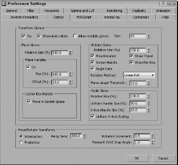
For the Move Gizmo section, you can set the Relative Size of the gizmo, which is relative to the top Size value, so a setting of 100 percent makes the size of the gizmo a full 30, and a setting of 50 percent makes it 15, or half the full Size value. You also can select to turn the plane handles on or off and set their Size and Offset values, which determine how large the highlighted planes are and where they are located relative to the center of the gizmo. A Size value of 100 percent extends the plane handles to be as long as the axis handles. You also can enable the Center Box Handle for moving in all three axes.
The Rotate Gizmo preferences also include a Relative Size value. The Free Rotation option enables you to click and drag between the axes to rotate the object freely along all axes. The Show Tripod option displays the axes tripod at the center of the object. The Screen Handle option displays an additional gray circle that surrounds all the axes. Dragging on this handle spins the object about the viewport's center. The Show Pie Slice highlights a slice along the selected axis that is as big as the offset distance. The Angle Data option displays the rotation values above the gizmo as it's being rotated.
The Gizmos panel offers three Rotation Methods: Linear Roll, Circular Crank, and Legacy R4. The Linear Roll method displays a tangent line at the source point where the rotation starts. The Circular Crank method rotates using the gizmo axes that surround the object. The Legacy R4 method uses a gizmo that looks just like the Move Gizmo that was available in the previous Max version. The Planar Angle Threshold value determines the minimum value to rotate within a plane.
The Scale Gizmo section also can set a Relative Size of the gizmo. The Uniform Handle Size value sets the size of the inner triangle, and the 2-Axis Handle Size value sets the size of the outer triangle. The Uniform 2-Axis Scaling option makes scaling with the outer triangle uniform along both axes.
The Move/Rotate Transforms section has some additional settings that control how objects move in the Perspective viewport. The Intersection and Projection options are for two different modes. The Intersection mode moves objects faster the farther they get from the center. In Projection mode, the Perspective Sensitivity value is used to set the mouse movements to the distance of the transformation. Small values result in small transformations for large mouse drags. The Rotation Increment value sets the amount of rotation that occurs for a given mouse drag distance, and the Viewport Arc Rotate Snap Angle sets where the arc snaps to.
Using the Transform Toolbox
The Transform Toolbox, shown in Figure 7.4, is a pop-up panel that offers quick access to the most common transformation operations. You can open this panel using the Edit ![]() Transform Toolbox menu command. The panel can be docked to the side of the interface by dragging it near the window border.
Transform Toolbox menu command. The panel can be docked to the side of the interface by dragging it near the window border.
FIGURE 7.4 The Transform Toolbox provides quick access to the most common transformation operation.
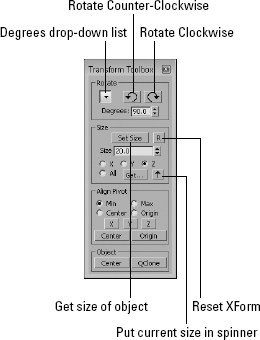
The Transform Toolbox is divided into four sections—Rotate, Size, Align Pivot, and Object. The Rotate section includes buttons for rotating the current selection by a set number of degrees in a clockwise or counterclockwise direction based on the current view. The drop-down list includes rotation values ranging from 1, 5, and 10 up to 180 and 240.
The Size section includes controls for scaling objects. The Set Size button scales the current object to the Size value along the specified axis or uniformly if the All option is selected. The R button resets the object transform by automatically applying the XForm modifier and then collapsing the stack to its base object. The Get button opens a small pop-up panel that lists the scale values for each of the axes and the Put Size button places the scale value for the selected object in the Size field for the specified axis.
The Align Pivot section changes the location of the selected object's pivot without having to open the Hierarchy panel. Using the Min, Max, Center, and Origin options, you can move the pivot's origin for the X, Y, or Z axes or you can use the Center and Origin buttons to move it for all three axes.
The Object section includes only two buttons. The Center button moves the entire object to the world's origin. The QClone button, which stands for Quick Clone, creates a duplicate object and moves it to the side of the original object.
Cross-Reference
More information on the Quick Clone feature is available in Chapter 8, “Cloning Objects and Creating Object Arrays.”
Using the Transform Type-In dialog box
The Transform Type-In dialog box (F12) lets you input precise values for moving, rotating, and scaling objects. This command provides more exact control over the placement of objects than dragging with the mouse.
The Transform Type-In dialog box allows you to enter numerical coordinates or offsets that can be used for precise transformations. Open this dialog box by choosing Edit ![]() Transform Type-In or by pressing the F12 key.
Transform Type-In or by pressing the F12 key.
Tip
Right-clicking any of the transform buttons opens the Transform Type-In dialog box for the transform button that is clicked on.
The Transform Type-In dialog box is modeless and allows you to select new objects as needed or to switch between the various transforms. When the dialog box appears, it displays the coordinate locations for the pivot point of the current selection in the Absolute: World column.
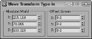
Within the Transform Type-In dialog box are two columns. The first column displays the current Absolute coordinates. Updating these coordinates transforms the selected object in the viewport. The second column displays the Offset values. These values are all set to 0.0 when the dialog box is first opened, but changing these values transforms the object along the designated axis by the entered value. Figure 7.5 shows the Transform Type-In dialog box for the Move Transform.
Note
The name of this dialog box changes depending on the type of transformation taking place and the coordinate system. If the Select and Move button is selected along with the world coordinate system, the Transform Type-In dialog box is labeled Move Transform Type-In, and the column titles indicate the coordinate system.
FIGURE 7.5 The Transform Type-In dialog box displays the current Absolute coordinates and Offset values.
Using the status bar Type-In fields
The status bar includes three fields labeled X, Y, and Z for displaying transformation coordinates. When you move, rotate, or scale an object, the X, Y, and Z offset values appear in these fields. The values depend on the type of transformation taking place. Translation shows the unit distances, rotation displays the angle in degrees, and scaling shows a percentage value of the original size.
When you click the Select Objects button, these fields show the absolute position of the cursor in world coordinates based on the active viewport.
You also can use these fields to enter values, as with the Transform Type-In dialog box. The type of transform depends on which transform button you select. The values that you enter can be either absolute coordinates or offset values, depending on the setting of the Transform Type-In toggle button that appears to the left of the transform fields. This toggle button lets you switch between Absolute and Offset modes, as shown in Table 7.2.
Tip
If you right-click any of these fields, a pop-up menu appears where you can cut, copy, or paste the current value.
TABLE 7.2 Absolute/Offset Buttons
| Button | Description |
| Absolute | |
| Offset |
Understanding the Transform Managers
To keep track of the position of every object in a scene, internally Max records the position of the object's vertices in reference to a Universal Coordinate System (UCS). This coordinate system defines vertex position using the X, Y, and Z coordinates from the scene's origin.
However, even though Max uses the UCS to internally keep track of all the points, this isn't always the easiest way to reference the position of an object. Imagine a train with several cars. For each individual train car, it is often easier to describe its position as an offset from the car in front of it.
The Transform Managers are three types of controls that help you define the system about which objects are transformed. These controls, found on the main toolbar and on the Axis Constraints toolbar, directly affect your transformations. They include the following:
- Reference Coordinate System: Defines the coordinate system about which the transformations take place.
- Transform Center settings: The Pivot Point Center, the Selection Center, and the Transform Coordinate Center. These settings specify the center about which the transformations take place.
- Axis Constraint settings: Allow the transformation to happen using only one axis or plane. These buttons are on the Axis Constraints toolbar.
Understanding reference coordinate systems
Max supports several reference coordinate systems based on the UCS, and knowing which reference coordinate system you are working with as you transform an object is important. Using the wrong reference coordinate system can produce unexpected transformations.
Within the viewports, the UCS coordinates are displayed as a set of coordinates in the lower-left corner of the viewport, and the Transform Gizmo is oriented with respect to the reference coordinate system.
To understand the concept of reference coordinate systems, imagine that you're visiting the Grand Canyon and are standing precariously on the edge of a lookout. To nervous onlookers calling the park rangers, the description of your position varies from viewpoint to viewpoint. A person standing by you would say you are next to him. A person on the other side of the canyon would say that you're across from her. A person at the floor of the canyon would say you're above him. And a person in an airplane would describe you as being on the east side of the canyon. Each person has a different viewpoint of you (the object), even though you have not moved.
Max recognizes the following reference coordinate systems:
- View Coordinate System: A reference coordinate system based on the viewports; X points right, Y points up, and Z points out of the screen (toward you). The views are fixed, making this perhaps the most intuitive coordinate system to work with.
- Screen Coordinate System: Identical to the View Coordinate System, except the active viewport determines the coordinate system axes, whereas the inactive viewports show the axes as defined by the active viewport.
- World Coordinate System: Specifies X pointing to the right, Z pointing up, and Y pointing into the screen (away from you). The coordinate axes remain fixed regardless of any transformations applied to an object. For Max, this system matches the UCS.
- Parent Coordinate System: Uses the reference coordinate system applied to a linked object's parent and maintains consistency between hierarchical transformations. If an object doesn't have a parent, then the world is its parent and the system works the same as the World Coordinate System.
- Local Coordinate System: Sets the coordinate system based on the selected object. The axes are located at the pivot point for the object. You can reorient and move the pivot point using the Pivot button in the Hierarchy panel.
- Gimbal Coordinate System: Provides interactive feedback for objects using the Euler XYZ controller. If the object doesn't use the Euler XYZ controller, then this coordinate system works just like the World Coordinate System.
- Grid Coordinate System: Uses the coordinate system for the active grid.
- Working Coordinate System: Lets you transform the selected object about the scene's Working Pivot as defined in the Hierarchy panel.
- Pick Coordinate System: Lets you select an object about which to transform. The Coordinate System list keeps the last four picked objects as coordinate system options.
All transforms occur relative to the current reference coordinate system as selected in the Referenced Coordinate System drop-down list found on the main toolbar.
Each of the three basic transforms can have a different coordinate system specified, or you can set it to change uniformly when a new coordinate system is selected. To do this, open the General panel in the Preference Settings dialog box and select the Constant option in the Reference Coordinate System section.
Using a transform center
All transforms are done about a center point. When transforming an object, you must understand what the object's current center point is, as well as the coordinate system in which you're working.
The Transform Center flyout consists of three buttons: Use Pivot Point Center, Use Selection Center, and Use Transform Coordinate Center, which are shown in Table 7.3. Each of these buttons alters how the transformations are done. The origin of the Transform Gizmo is always positioned at the center point specified by these buttons.
TABLE 7.3 Transform Center Buttons
| Button | Description |
| Use Pivot Point Center | |
| Use Selection Center | |
| Use Transform Coordinate Center |
Pivot Point Center
Pivot points are typically set to the center of an object when the object is first created, but they can be relocated anywhere within the scene including outside of the object. Relocating the pivot point allows you to change the point about which objects are rotated. For example, if you have a car model that you want to position along an incline, moving the pivot point to the bottom of one of the tires allows you to easily line up the car with the incline.
If you select the Use Pivot Point Center button, then the Select and Rotate tool rotates about the pivot point for the selected object, which can be located anywhere in the scene.
Note
Pivot points are discussed in detail in the next section.
Selection Center
The Use Selection Center button sets the transform center to the center of the selected object or objects regardless of the individual object's pivot point. If multiple objects are selected, then the center is computed to be in the middle of a bounding box that surrounds all the objects.
Transform Coordinate Center
The Transform Coordinate Center button uses the center of the Local Coordinate System. If the View Coordinate System is selected, then all objects are transformed about the center of the viewport grid. If an object is selected as the coordinate system using the Pick option, then all transformations are transformed about that object's center.
When you select the Local Coordinate System, the Use Transform Center button is ignored and objects are transformed about their local axes. If you select multiple objects, then they all transform individually about their local axes. Grouped objects transform about the group axes.
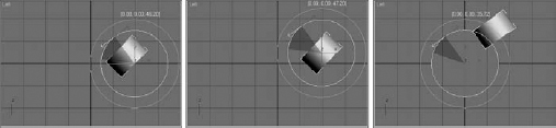
For example, the default pivot point for a Cylinder object is in the middle of the cylinder's base, so if the Transform Center is set to the Use Pivot Point option, then the cylinder rotates about its base pivot point. If the Use Selection Center option is selected, then the cylinder rotates about its center point. If the Use Transform Coordinate Center option is selected for the View Coordinate System, then the cylinder is rotated about the grid origin.
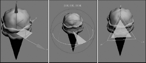
Figure 7.6 shows a simple cylinder object in the Left viewport using the different transform center modes. The left image shows the Pivot Point Center mode, the middle image shows the Selection Center mode with both objects selected, and the right image shows the Transform Coordinate Center mode. For each mode, notice that the Rotate Gizmo is located at different locations.
FIGURE 7.6 The Rotate Gizmo is located in different places, depending on the selected Transform Center mode.
Selecting Axis Constraints
Three-dimensional space consists of three basic directions defined by three axes: X, Y, and Z. If you were to stand on each axis and look at a scene, you would see three separate planes: the XY plane, the YZ plane, and the ZX plane. These planes show only two dimensions at a time and restrict any transformations to the two axes. These planes are visible from the Top, Left, and Front viewports.
By default, the Top, Left, and Front viewports show only a single plane and thereby restrict transformations to that single plane. The Top view constrains movement to the XY plane, the Left or Right side view constrains movement to the YZ plane, and the Front view constrains movement to the ZX plane. This setting is adequate for most modeling purposes, but sometimes you might need to limit the transformations in all the viewports to a single plane. In Max, you can restrict movement to specific transform axes using the Restrict Axes buttons in the Axis Constraints toolbar. You access this toolbar, shown in Figure 7.7, by right-clicking the main toolbar (away from the buttons) and selecting Axis Constraints options from the pop-up menu.
FIGURE 7.7 The Axis Constraints toolbar includes buttons for restricting transformations to a single axis or plane.
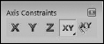
The first four buttons on this toolbar are Restrict axes buttons: Restrict to X (F5); Restrict to Y (F6); Restrict to Z (F7); and the flyout buttons, Restrict to XY, YZ, and ZX Plane (F8). The last button is the Snaps Use Axis Constraints toggle button. The effect of selecting one of the Restrict axes buttons is based on the selected coordinate system. For example, if you click the Restrict to X button and the reference coordinate system is set to View, then the object always transforms to the right because, in the View Coordinate System, the X-axis is always to the right. If you click the Restrict to X button and the coordinate system is set to Local, the axes are attached to the object, so transformations along the X-axis are consistent in all viewports (with this setting, the object does not move in the Left view because it shows only the YZ plane).
Caution
If the axis constraints don't seem to be working, check the Preference Settings dialog box and look at the General panel to make sure that the Reference Coordinate System option is set to Constant.
Additionally, you can restrict movement to a single plane with the Restrict to Plane flyouts consisting of Restrict to XY, Restrict to YZ, and Restrict to ZX. (Use the F8 key to cycle quickly through the various planes.)
Note
If the Transform Gizmo is enabled, then the axis or plane that is selected in the Axis Constraints toolbar initially is displayed in yellow. If you transform an object using a Transform Gizmo, then the respective Axis Constraints toolbar button is selected after you complete the transform.
Locking axes transformations
To lock an object's transformation axes on a more permanent basis, go to the Command Panel and select the Hierarchy tab. Click the Link Info button to open the Locks rollout, shown in Figure 7.8. The rollout displays each axis for the three types of transformations: Move, Rotate, and Scale. Make sure that the object is selected, and then click the transformation axes that you want to lock. Be aware that if all Move axes are selected, you won't be able to move the object until you deselect the axes.
Note
Another option is to use the Display floater to freeze the object.
Locking axes is helpful if you want to prevent accidental scaling of an object or restrict a vehicle's movement to a plane that makes up a road.
FIGURE 7.8 The Locks rollout can prevent any transforms along an axis.
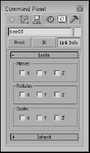
The Locks rollout displays unselected X, Y, and Z check boxes for the Move, Rotate, and Scale transformations. By selecting the check boxes, you limit the axes about which the object can be transformed. For example, if you check the X and Y boxes under the Move transformation, the object can move only in the Z direction of the Local Coordinate System.
Note
These locks work regardless of the axis constraint settings.
Tutorial: Landing a spaceship in port
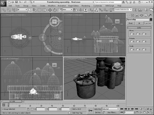
Transformations are the most basic object manipulation that you will do and probably the most common. This tutorial includes a spaceship object and a spaceport. The goal is to position the spaceship on the landing pad of the spaceport, but it is too big and in the wrong spot. With a few clever transformations, you'll be set.
To transform a spaceship to land in a spaceport, follow these steps:
- Open the Transforming spaceship.max file from the Chap 07 directory on the CD.
- To prevent any extraneous movements of the spaceport, select the spaceport by clicking it. Open the Hierarchy panel, and click the Link Info button. Then in the Locks rollout, select all nine boxes to restrict all transformations so that that spaceport won't be accidentally moved.
- To position the spaceship over the landing platform, select the spaceship object and click the Select and Move button in the main toolbar (or press the W key). The Move Gizmo appears in the center of the spaceship object. If you don't see the Move Gizmo, press the X key. Make sure that the Reference Coordinate System is set to View and that the Use Selection Center option is enabled. Right-click the Left viewport to make it active, select the red X-axis line of the gizmo, and drag to the right until the center of the spaceship is over the landing pad.
- Right-click the Front viewport, and drag the red X-axis gizmo line to the left to line up the spaceship with the center of the landing pad.
- Click the Select and Uniform Scale button (or press the R key). Place the cursor over the center gizmo triangle, and drag downward until the spaceship fits within the landing pad.
- Click the Select and Move button again (or press the W key), and drag the green Y-axis gizmo line downward in the Front viewport to move the spaceship toward the landing pad.
- Click the Select and Rotate button (or press the E key). Right-click the Top viewport, and drag the blue Z-axis gizmo circle downward to rotate the spaceship clockwise so that its front end points away from the buildings.
FIGURE 7.9 Transformation buttons and the Transform Gizmos were used to position this spaceship.
Using Pivot Points
An object's pivot point is the center about which the object is rotated and scaled and about which most modifiers are applied. Pivot points are created by default when an object is created and are usually created at the center or base of an object. You can move and orient a pivot point in any direction, but repositioning the pivot cannot be animated. Pivot points exist for all objects, whether or not they are part of a hierarchy.
Caution
Try to set your pivot points before animating any objects in your scene. If you relocate the pivot point after animation keys have been placed, all transformations are modified to use the new pivot point.
Positioning pivot points
To move and orient a pivot point, open the Hierarchy panel in the Command Panel and click the Pivot button. At the top of the Adjust Pivot rollout are three buttons; each button represents a different mode. The Affect Pivot Only mode makes the transformation buttons affect only the pivot point of the current selection. The object does not move. The Affect Object Only mode causes the object to be transformed, but not the pivot point. The Affect Hierarchy Only mode allows an object's links to be moved.
The pivot point is easily identified as the place where the Transform Gizmo is located when the object is selected, as shown in Figure 7.10.
FIGURE 7.10 The Transform Gizmo is located at the object's pivot point.
Note
Using the Scale transformation while one of these modes is selected alters the selected object but has no effect on the pivot point or the link.
Aligning pivot points
Below the mode buttons are three more buttons that are used to align the pivot points. These buttons are active only when a mode is selected. These buttons are Center to Object/Pivot, Align to Object/Pivot, and Align to World. The first two buttons switch between Object and Pivot, depending on the mode selected. You may select only one mode at a time. The button turns light blue when selected.
The Center to Object button moves the pivot point so that it is aligned with the object center, and the Center to Pivot button moves the object so it is centered on its own pivot point. The Align to Object/Pivot button rotates the object or pivot point until the object's Local Coordinate System and the pivot point are aligned. The Align to World button rotates either the object or the pivot to the World Coordinate System. For example, if the Affect Object Only mode is selected and the object is separated from the pivot point, clicking the Center to Pivot button moves the object so that its center is on the pivot point.
Under these three alignment buttons is another button labeled Reset Pivot, which you use to reset the pivot point to its original location.
Using the Working Pivot
Underneath the Adjust Pivot rollout is the Working Pivot rollout. Working Pivots are handy if you want to position an object using a temporary pivot without having to change the default object pivot. To position a Working Pivot, click the Edit Working Pivot button. This enters a mode just like the Affect Pivot Only button described previously, except it works with the working pivot.
After the Working Pivot is in place, you can select to use it instead of the object pivot by clicking the Use Working Pivot button. The Working Pivot stays active until you disable it in the Hierarchy panel. The Working Pivot works for all objects in the scene. When the Working Pivot is active, reminder text “USE WP” appears in all the viewports under the viewport name; when the Edit Working Pivot mode is enabled, this text reads, “EDIT WP.”
Tip
You can quickly enable the Working Pivot by selecting the Working option from the Reference Coordinate System drop-down list in the main toolbar.
The Working Pivot rollout includes several buttons to help position the Working Pivot. The Align to View button reorients the Working Pivot to the current view. The Reset button moves the Working Pivot to the object pivot location of the selected object or to the view center if no object is selected.
Note
There is only one working pivot that you can use, but it can be used by any selected object.
The View button enters a mode identified by “EDIT WP” in the viewports that lets you place the Working Pivot anywhere in the current viewport by simply clicking where it should be. This is great for visually eyeballing the Working Pivots location. The Surface button (also identified by the EDIT WP text in the viewport) enters a mode where you can position the Working Pivot on the surface of an object by interactively dragging the cursor over the object surface. The cursor automatically reorients itself to be aligned with the surface normal. If the Align to View option is selected, then the Working Pivot is automatically aligned to the current view.
Transform adjustments
The Hierarchy panel of the Command Panel includes another useful rollout labeled Adjust Transform. This rollout includes another mode that you can use with hierarchies of objects. Clicking the Don't Affect Children button places you in a mode where any transformations of a linked hierarchy don't affect the children. Typically, transformations are applied to all linked children of a hierarchy, but this mode disables that.
The Adjust Transform rollout also includes two buttons that allow you to reset the Local Coordinate System and scale percentage. These buttons set the current orientation of an object as the World coordinate or as the 100 percent standard. For example, if you select an object, move it 30 units to the left, and scale it to 200 percent, these values are displayed in the coordinate fields on the status bar. Clicking the Reset Transform and Reset Scale buttons resets these values to 0 and 100 percent.
You use the Reset Scale button to reset the scale values for an object that has been scaled using non-uniform scaling. Non-uniform scaling can cause problems for child objects that inherit this type of scaling, such as shortening the links. The Reset Scale button can remedy these problems by resetting the parent's scaling values. When the scale is reset, you won't see a visible change to the object, but if you open the Scale Transform Type-In dialog box while the scale is being reset, you see the absolute local values being set back to 100 each.
If you are using an object that has been non-uniformly scaled, using Reset Scale before the item is linked saves you some headaches if you plan on using modifiers.
Using the Reset XForm utility
You also can reset transform values using the Reset XForm utility. To use this utility, open the Utility panel and click the Reset XForm button, which is one of the default buttons. The benefit of this utility is that you can reset the transform values for multiple objects simultaneously. This happens by applying the XForm modifier to the objects. The rollout for this utility includes only a single button labeled Reset Selected.
Tutorial: A bee buzzing about a flower
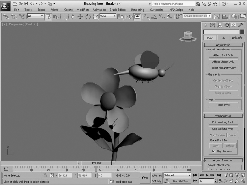
By adjusting an object's pivot point, you can control how the object is transformed about the scene. In this example, you animate a bee's flapping wings by repositioning the wings’ pivot points. You then reposition the pivot point for the entire bee so it can rotate about the flower object.
To control how a bee rotates about a flower, follow these steps:
- Open the Buzzing bee.max file from the Chap 07 directory on the CD.
This file includes a bee created from primitives and a flower model created by Zygote Media.
- Click the bee object to select it, and press Z to zoom in on it in all viewports. Click the right wing, open the Hierarchy panel, and click the Affect Pivot Only button. This displays the pivot point in the center of the wing oriented to the wing surface. Select the Local coordinate system from the list in the main toolbar. This orients the Transform Gizmo to match the pivot's orientation. Drag the wing's pivot point along its X-axis to the place where the wing contacts the body object. Then disable the Affect Pivot Only button. Then select and repeat this step for the left wing.
- Click the Auto Key button (or press N) to enable animate mode, and drag the Time Slider to frame 1. Then, with the Select and Rotate button (E), rotate the wing about its Z-axis until it is almost vertical in the Front viewport. Notice how the wing rotates about its new pivot point. Then drag the Time Slider to frame 2, and rotate the wing back to its original position. Click the Auto Key button again (N) to disable key mode.
- If you want to make these rotations repeat throughout the animation using the Track View, right-click the wing object and select Curve Editor in the pop-up quadmenu that appears. This opens a Track View with the Rotation tracks selected. In the Track View, select Controller
 Out-of-Range Types to open the Param Out-of-Range Types dialog box, select the Loop option, and click OK. Then close the Track View.
Cross-Reference
Working with the Track View is beyond the scope of this chapter, but you can find more information on the Track View in Chapter 37, “Working with the F-Curve Editor in the Track View.”
- Repeat Steps 3 and 4 for the second wing object. Press the Play Animation button to see both wings flap for the entire animation.
- Select all parts that make up the bee in the Top viewport, select Group Group, and name the object bee. Then select the bee and the flower in the Left viewport, and press Z to zoom in on them.
- With the bee group selected, click the Affect Pivot Only button in the Hierarchy panel and move the pivot point to the center of the flower in the Front viewport. Click the Affect Pivot Only button again to disable it.
Note
If you don't want to move the object pivot in Step 7, you can use the Working Pivot to rotate the bee around the flower, or you could select the Pick coordinate system and select the flower.
- Enable the Auto Key button (N) again, and drag to frame 35. With the Select and Rotate button (E), rotate the bee in the Top viewport a third of the way around the flower. Drag the Time Slider to frame 70, and rotate the bee another third of the way. With the Time Slider at frame 100, complete the rotation. Click the Auto Key button again to display key mode.
- Click the Play button (/) to see the final rotating bee.
Figure 7.11 shows the bee as it moves around the flower where its pivot point is located.
FIGURE 7.11 By moving the pivot point of the bee, you can control how it spins about the flower.
Using the Align Commands
The Align commands are an easy way to automatically transform objects. You can use these commands to line up object centers or edges, align normals and highlights, align to views and grids, and even line up cameras.
Aligning objects
![]() Any object that you can transform, you can align, including lights, cameras, and Space Warps. After selecting the object to be aligned, click the Align flyout button on the main toolbar or choose Tools
Any object that you can transform, you can align, including lights, cameras, and Space Warps. After selecting the object to be aligned, click the Align flyout button on the main toolbar or choose Tools ![]() Align
Align ![]() Align (or press Alt+A). The cursor changes to the Align icon. Now, click a target object with which you want to align all the selected objects. Clicking the target object opens the Align Selection dialog box with the target object's name displayed in the dialog box's title, as shown in Figure 7.12.
Align (or press Alt+A). The cursor changes to the Align icon. Now, click a target object with which you want to align all the selected objects. Clicking the target object opens the Align Selection dialog box with the target object's name displayed in the dialog box's title, as shown in Figure 7.12.
FIGURE 7.12 The Align Selection dialog box can align objects along any axes by their Minimum, Center, Pivot, or Maximum points.
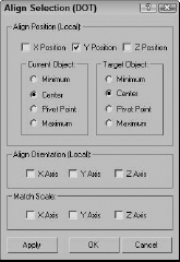
The Align Selection dialog box includes settings for the X, Y, and Z positions to line up the Minimum, Center, Pivot Point, or Maximum dimensions for the selected or target object's bounding box. As you change the settings in the dialog box, the objects reposition themselves, but the actual transformations don't take place until you click Apply or OK.
Cross-Reference
Another way to align objects is with the Clone and Align tool, which is covered in Chapter 8, “Cloning Objects and Creating Object Arrays.”
Using the Quick Align tool
![]() The first flyout tool under the Align tool in the main toolbar (and in the Tools menu) is the Quick Align tool (Shift+A). This tool aligns the pivot points of the selected object with the object that you click without opening a separate dialog box. This is much more helpful than the Align tool, which causes a separate dialog box to open.
The first flyout tool under the Align tool in the main toolbar (and in the Tools menu) is the Quick Align tool (Shift+A). This tool aligns the pivot points of the selected object with the object that you click without opening a separate dialog box. This is much more helpful than the Align tool, which causes a separate dialog box to open.
Aligning normals
You can use the Normal Align command to line up points of the surface of two objects. A Normal vector is a projected line that extends from the center of a polygon face exactly perpendicular to the surface. When two Normal vectors are aligned, the objects are perfectly adjacent to one another. If the two objects are spheres, then they touch at only one point.
![]() To align normals, you need to first select the object to move (this is the source object). Then choose Tools
To align normals, you need to first select the object to move (this is the source object). Then choose Tools ![]() Align
Align ![]() Normal Align or click the Normal Align flyout button under the Align button on the main toolbar (or press Alt+N). The cursor changes to the Normal Align icon. Drag the cursor across the surface of the source object, and a blue arrow pointing out from the face center appears. Release the mouse when you've correctly pinpointed the position to align.
Normal Align or click the Normal Align flyout button under the Align button on the main toolbar (or press Alt+N). The cursor changes to the Normal Align icon. Drag the cursor across the surface of the source object, and a blue arrow pointing out from the face center appears. Release the mouse when you've correctly pinpointed the position to align.
Next, click the target object, and drag the mouse to locate the target object's align point. This is displayed as a green arrow. When you release the mouse, the source object moves to align the two points and the Normal Align dialog box appears, as shown in Figure 7.13.
FIGURE 7.13 The Normal Align dialog box allows you to define offset values when aligning normals.
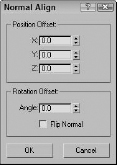
When the objects are aligned, the two points match up exactly. The Normal Align dialog box lets you specify offset values that you can use to keep a distance between the two objects. You also can specify an Angle Offset, which is used to deviate the parallelism of the normals. The Flip Normal option aligns the objects so that their selected normals point in the same direction.
Objects without any faces, like Point Helper objects and Space Warps, use a vector between the origin and the Z-axis for normal alignment.
Tutorial: Aligning a kissing couple
Aligning normals positions two object faces directly opposite one another, so what better way to practice this tool than to align two faces?
To connect the kissing couple using the Normal Align command, follow these steps:
- Open the Kissing couple.max file from the Chap 07 directory on the CD.
This file includes two extruded shapes of a boy and a girl. The extruded shapes give you flat faces that are easy to align.
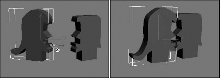
- Select the girl shape, and choose the Tools Align Normal Align menu command (or press Alt+N). Then click and drag the cursor over the extruded shape until the blue vector points out from the front of the lips, as shown in Figure 7.14.
- Then click and drag the cursor over the boy shape until the green vector points out from the front of the lips. This vector pointing out from the face is the surface normal. Then click and release the mouse, and the Normal Align dialog box appears. Enter a value of 5 in the Z-Axis Offset field, and click OK.
Figure 7.14 shows the resulting couple with normal aligned faces.
FIGURE 7.14 Using the Normal Align feature, you can align object faces.
Cross-Reference
In the Align button flyout are two other common ways to align objects: Align Camera and Place Highlight (Ctrl+H). To learn about these features, see Chapter 19, “Configuring and Aiming Cameras,” and Chapter 20, “Using Lights and Basic Lighting Techniques,” respectively.
Aligning to a view
![]() The Align to View command provides an easy and quick way to reposition objects to one of the axes. To use this command, select an object and choose Tools
The Align to View command provides an easy and quick way to reposition objects to one of the axes. To use this command, select an object and choose Tools ![]() Align
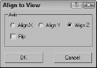
Align ![]() Align to View. The Align to View dialog box appears, as shown in Figure 7.15. Changing the settings in this dialog box displays the results in the viewports. You can use the Flip command for altering the direction of the object points. If no object is selected, then the Align to View command cannot be used.
Align to View. The Align to View dialog box appears, as shown in Figure 7.15. Changing the settings in this dialog box displays the results in the viewports. You can use the Flip command for altering the direction of the object points. If no object is selected, then the Align to View command cannot be used.
FIGURE 7.15 The Align to View dialog box is a quick way to line up objects with the axes.
The Align to View command is especially useful for fixing the orientation of objects when you create them in the wrong view. All alignments are completed relative to the object's Local Coordinate System. If several objects are selected, each object is reoriented according to its Local Coordinate System.
Note
Using the Align to View command on symmetrical objects like spheres doesn't produce any noticeable difference in the viewports.
Using Grids
When Max is started, the one element that is visible is the Home Grid. This grid is there to give you a reference point for creating objects in 3D space. At the center of each grid are two darker lines. These lines meet at the origin point for the World Coordinate System where the coordinates for X, Y, and Z are all 0.0. This point is where all objects are placed by default.
In addition to the Home Grid, you can create and place new grids in the scene. These grids are not rendered, but you can use them to help you locate and align objects in 3D space.
The Home Grid
You can turn the Home Grid on and off by choosing Tools ![]() Grid and Snaps
Grid and Snaps ![]() Show Home Grid. (You also can turn the Home Grid on and off for the active viewport using the G key.) If the Home Grid is the only grid in the scene, then by default it is also the construction grid where new objects are positioned when created.
Show Home Grid. (You also can turn the Home Grid on and off for the active viewport using the G key.) If the Home Grid is the only grid in the scene, then by default it is also the construction grid where new objects are positioned when created.
You can access the Home Grid parameters (shown in Figure 7.16) by choosing Tools ![]() Grid and Snaps
Grid and Snaps ![]() Grid and Snap Settings. You also can access this dialog box by right-clicking the Snap, Angle Snap, or Percent Snap toggle buttons located on the main toolbar.
Grid and Snap Settings. You also can access this dialog box by right-clicking the Snap, Angle Snap, or Percent Snap toggle buttons located on the main toolbar.
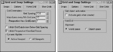
In the Home Grid panel of the Grid and Snap Settings dialog box, you can set how often Major Lines appear, as well as Grid Spacing. (The Spacing value for the active grid is displayed on the status bar.) You also can specify to dynamically update the grid view in all viewports or just in the active one.
The User Grids panel lets you activate any new grids when created.
FIGURE 7.16 The Home Grid and User Grids panels of the Grid and Snap Settings dialog box let you define the grid spacing.
Creating and activating new grids
In addition to the Home Grid, you can create new grids. To create a new Grid object, select the Create ![]() Helpers
Helpers ![]() Grid menu command, or open the Create panel, select the Helpers category, and click the Grid button. In the Parameters rollout are settings for specifying the new grid object's dimensions, spacing, and color, as well as which coordinate plane to display (XY, YZ, or ZX).
Grid menu command, or open the Create panel, select the Helpers category, and click the Grid button. In the Parameters rollout are settings for specifying the new grid object's dimensions, spacing, and color, as well as which coordinate plane to display (XY, YZ, or ZX).
You can designate any newly created grid as the default active grid. To activate a grid, make sure that it is selected and choose Tools ![]() Grid and Snaps
Grid and Snaps ![]() Activate Grid Object. Keep in mind that only one grid may be active at a time and that the default Home Grid cannot be selected. You also can activate a grid by right-clicking the grid object and selecting Activate Grid from the pop-up menu. To deactivate the new grid and reactivate the Home Grid, choose Tools
Activate Grid Object. Keep in mind that only one grid may be active at a time and that the default Home Grid cannot be selected. You also can activate a grid by right-clicking the grid object and selecting Activate Grid from the pop-up menu. To deactivate the new grid and reactivate the Home Grid, choose Tools ![]() Grid and Snaps
Grid and Snaps ![]() Activate Home Grid, or right-click the grid object and choose Activate Grid
Activate Home Grid, or right-click the grid object and choose Activate Grid ![]() Home Grid from the pop-up quadmenu.
Home Grid from the pop-up quadmenu.
You can find further grid settings for new grids in the Grid and Snap Settings dialog box on the User Grids panel. The settings include automatically activating the grid when created and an option for aligning an AutoGrid using World space or Object space coordinates.
Using AutoGrid
You can use the AutoGrid feature to create a new construction plane perpendicular to a face normal. This feature provides an easy way to create and align objects directly next to one another without manually lining them up or using the Align features.
The AutoGrid feature shows up as a check box at the top of the Object Type rollout for every category in the Create panel. It becomes active only when you're in Create Object mode.
To use AutoGrid, click the AutoGrid option after selecting an object type to create. If no objects are in the scene, then the object is created as usual. If an object is in the scene, then the cursor moves around on the surface of the object with its coordinate axes perpendicular to the surface that the cursor is over. Clicking and dragging creates the new object based on the precise location of the object under the mouse.
The AutoGrid option stays active for all new objects that you create until you turn it off by unchecking the box.
Tip
Holding down the Alt key before creating the object makes the new construction grid visible, disables the AutoGrid option, and causes all new objects to use the new active construction grid. You can disable this active construction grid by enabling the AutoGrid option again.
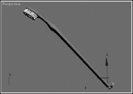
Tutorial: Creating a spyglass
As you begin to build objects for an existing scene, you find that working away from the scene origin is much easier if you enable the AutoGrid feature for the new objects you create. This feature enables you to position the new objects on (or close to) the surfaces of the nearby objects. It works best with objects that have pivot points located at their edges, such as Box and Cylinder objects.
In this example, you quickly create a spyglass object using the AutoGrid without needing to perform additional moves.
To create a spyglass using the AutoGrid and Snap features, follow these steps:
- Before starting, click the Left viewport and zoom way out so you can see the height of the spyglass pieces.
- Select Create Standard Primitives Cylinder, and drag from the origin in the Top viewport to create a Cylinder object. Set the Radius value to 40 and the Height value to 200. Then enable the AutoGrid option in the Object Type rollout.
- Drag from the origin again in the Top viewport to create another Cylinder object. Set its Radius to 35 and its Height to 200. Repeat this step three times, reducing the Radius by 5 each time.
Figure 7.17 shows the resulting spyglass object.
FIGURE 7.17 This spyglass object was created quickly and easily using the AutoGrid option.

Using Snap Options
Often, when an object is being transformed, you know exactly where you want to put it. The Snap feature can be the means whereby objects get to the precise place they should be. For example, if you are constructing a set of stairs from box primitives, you can enable the Edge Snap feature to make each adjacent step align precisely along the edge of the previous step. With the Snap feature enabled, an object automatically moves (or snaps) to the specified snap position when you place it close enough. If you enable the Snap features, they affect any transformations that you make in a scene.
Snap points are defined in the Grid and Snap Settings dialog box that you can open by choosing Tools ![]() Grid and Snaps
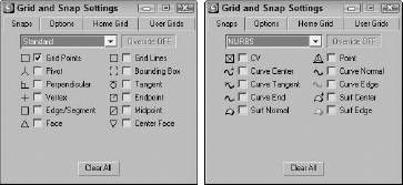
Grid and Snaps ![]() Grid and Snap Settings or by right-clicking any of the first three Snap buttons on the main toolbar. (These Snap buttons have a small magnet icon in them.) Figure 7.18 shows the Snaps panel of the Grid and Snap Settings dialog box for Standard and Body objects. An option for configuring NURBS snapping also is available. NURBS stands for Non-Uniform Rational B-Splines. They are a special type of object created from spline curves.
Grid and Snap Settings or by right-clicking any of the first three Snap buttons on the main toolbar. (These Snap buttons have a small magnet icon in them.) Figure 7.18 shows the Snaps panel of the Grid and Snap Settings dialog box for Standard and Body objects. An option for configuring NURBS snapping also is available. NURBS stands for Non-Uniform Rational B-Splines. They are a special type of object created from spline curves.
Cross-Reference
For more information on NURBS, see Bonus Chapter 5 on the CD, “Working with NURBS.”
After snap points have been defined, the Snap buttons on the main toolbar activate the Snap feature, or you can press the S key. The first Snaps button consists of a flyout with three buttons: 3D Snap toggle, 2.5D Snap toggle, and 2D Snap toggle. The 2D Snap toggle button limits all snaps to the active construction grid. The 2.5D Snap toggle button snaps to points on the construction grid as well as projected points from objects in the scene. The 3D Snap toggle button can snap to any points in 3D space.
FIGURE 7.18 The Snaps panel includes many different points to snap to depending on the object type.
When snapping is enabled, a small circle appears at the center of the pivot point. This circle is a visual reminder that snapping is enabled. When you move an object while snapping is enabled, you can either drag the small circle to move the object freely between snapping points or drag the Move tool's controls to constraint the object's movement.
As you drag an object, the starting position is marked and a line is drawn between this starting point and the destination point. Available snapping points are marked with a set of cross-hairs. If you release the object, it snaps to the highlighted set of cross-hairs. The line connecting the starting and end points and the snapping point cross-hairs are colored green when the object is over an available snapping point and yellow when not.
In addition to the small circle icon and the Move tool controls, you can move the mouse over the object and any available snapping points on the object are highlighted. For example, if the Vertex option in the Grid and Snap Settings dialog box is enabled, moving the mouse over one of a box object's corners highlights the corner with a set of yellow cross-hairs. Dragging while a vertex's cross-hair is highlighted lets you snap the selected corner to another position.
Tutorial: Creating a 2D outline of an object
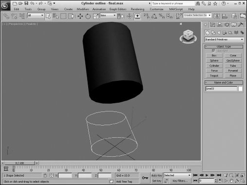
The 2.5D snap can be confusing. It limits snapping to the active construction grid, but within the active grid, it can snap to 3D points that are projected onto the active grid. You can create a 2D representation of a 3D object by snapping to the vertices of the suspended object.
To create a 2D outline of a cylinder object, follow these steps:
- Select the Create Standard Primitives Cylinder menu to create a simple cylinder object.
- Select and rotate the cylinder so it is suspended and rotated at an angle above the construction grid.
- Click and hold the Snap toggle button, and select the 2.5D Snap flyout option. Then right-click the Snap toggle and select only the Vertex option in the Snaps panel. Then close the Grid and Snap Settings dialog box.
- Choose the Create Shapes Line menu and create a line in the Top viewport by snapping to the points that make the outline of the cylinder.
Figure 7.19 shows the projected outline.
FIGURE 7.19 The 2.5D snap feature snaps to vertices of 3D objects projected onto the active grid.
Tip
Right-clicking the Snap toggle opens the Grid and Snap Settings dialog box, except for the Spinner Snap toggle, which opens the Preference Settings dialog box.
These Snap buttons control the snapping for translations. To the right are two other buttons: Angle Snap toggle and Percent Snap. These buttons control the snapping of rotations and scalings.
Note
The keyboard shortcut for turning the Snap feature on and off is the S key.
Setting snap points
The Snaps tab in the Grid and Snap Settings dialog box has many points that can be snapped to in two categories: Standard and NURBS. The Standard snap points (previously shown in Figure 7.18) include the following:
- Grid Points: Snaps to the Grid intersection points
- Grid Lines: Snaps only to positions located on the Grid lines
- Pivot: Snaps to an object's pivot point
- Bounding Box: Snaps to one of the corners of a bounding box
- Perpendicular: Snaps to a spline's next perpendicular point
- Tangent: Snaps to a spline's next tangent point
- Vertex: Snaps to polygon vertices
- Endpoint: Snaps to a spline's end point or the end of a polygon edge
- Edge/Segment: Snaps to positions only on an edge
- Midpoint: Snaps to a spline's midpoint or the middle of a polygon edge
- Face: Snaps to any point on the surface of a face
- Center Face: Snaps to the center of a face
Several snap points specific to NURBS objects, such as NURBS points and curves, are also shown in Figure 7.18. These points include:
- CV: Snaps to any NURBS Control Vertex subobject
- Point: Snaps to a NURBS point
- Curve Center: Snaps to the center of the NURBS curve
- Curve Normal: Snaps to a point that is normal to a NURBS curve
- Curve Tangent: Snaps to a point that is tangent to a NURBS curve
- Curve Edge: Snaps to the edge of a NURBS curve
- Curve End: Snaps to the end of a NURBS curve
- Surf Center: Snaps to the center of a NURBS surface
- Surf Normal: Snaps to a point that is normal to a NURBS surface
- Surf Edge: Snaps to the edge of a NURBS surface
Setting snap options
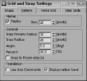
The Grid and Snap Settings dialog box holds a panel of Options, shown in Figure 7.20, in which you can set the marker size and whether they display. The Snap Preview Radius defines the radial distance from the snap point required before the object that is being moved is displayed at the target snap point as a preview. This value can be larger than the actual Snap Radius and is meant to provide visual feedback on the snap operation. The Snap Radius setting determines how close the cursor must be to a snap point before it snaps to it.
The Angle and Percent values are the strengths for any Rotate and Scale transformations, respectively. The Snap to Frozen Objects lets you control whether frozen items can be snapped to. You also can cause translations to be affected by the designated axis constraints with the Use Axis Constraints option. The Display Rubber Band option draws a line from the object's starting location to its snapping location.
Within any viewpoint, holding down the Shift key and right-clicking in the viewport can access a pop-up menu of grid points and options. This pop-up quadmenu lets you quickly add or reset all the current snap points and change snap options, such as Transformed Constraints and Snap to Frozen.
FIGURE 7.20 The Options panel includes settings for marker size and color and the Snap Strength value.
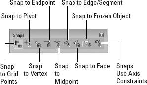
Using the Snaps toolbar
As a shortcut to enabling the various snapping categories, you can access the Snaps toolbar by right-clicking the main toolbar away from the buttons and selecting Snaps from the popup menu. The Snaps toolbar, shown in Figure 7.21, can have several toggle buttons enabled at a time. Each enabled button is highlighted in yellow.
FIGURE 7.21 The Snaps toolbar provides a quick way to access several snap settings.
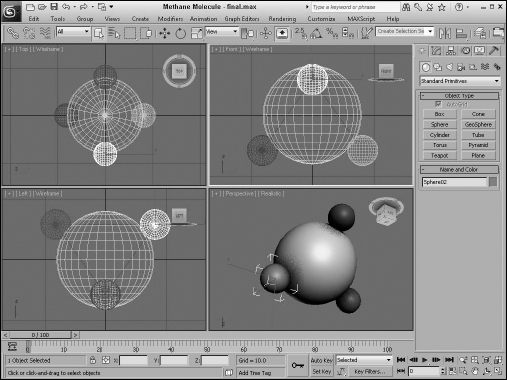
Tutorial: Creating a lattice for a methane molecule
Many molecules are represented by a lattice of spheres. Trying to line up the exact positions of the spheres by hand could be extremely frustrating, but using the Snap feature makes this challenge . . . well . . . a snap.
One of the simpler molecules is methane, which is composed of one carbon atom surrounded by four smaller hydrogen atoms. To reproduce this molecule as a lattice, you first need to create a tetrahedron primitive and snap spheres to each of its corners.
To create a lattice of the methane molecule, follow these steps:
- Right-click the Snap toggle button in the main toolbar to open the Grid and Snap Settings, and enable the Grid Points and Vertex options. Then click the Snap toggle button (or press the S key) to enable 3D Snap mode.
- Select the Create Extended Primitives Hedra menu command, set the P Family Parameter to 1.0, and drag in the Top viewport from the center of the Home Grid to the first grid point to the right to create a Tetrahedron shape.
- Click and hold the Snap toggle button, and select the 3D Snap flyout option. Select the Create Standard Primitives Sphere menu command. Right-click in the Left viewport, and drag from the top-left vertex to create a sphere. Set the sphere's Radius to 25.
- Create three more sphere objects with Radius values of 25 that are snapped to the vertices of the Tetrahedron object.
- Finally, create a sphere in the Top viewport using the same snap point as the initial tetrahedron. Set its Radius to 80.
Figure 7.22 shows the finished methane molecule.
FIGURE 7.22 A methane molecule lattice drawn with the help of the Snap feature
Summary
Transforming objects in Max is one of the fundamental actions you can perform. The three basic ways to transform objects are moving, rotating, and scaling. Max includes many helpful features to enable these transformations to take place quickly and easily. In this chapter, you learned these features:
- Using the Move, Rotate, and Scale buttons and the Transform Gizmos
- Transforming objects precisely with the Transform Type-In dialog box and status bar fields
- Using Transform Managers to change coordinate systems and lock axes
- Aligning objects with the align tool, aligning normals, and aligning to views
- Manipulating pivot points and using a Working Pivot
- Working with grids
- Setting up snap points
- Snapping objects to snap points
In the next chapter, you work more with multiple objects by learning how to clone objects. Using these techniques, you could very quickly have too many objects (and you were worried that there weren't enough objects).