
QUICK START
Laying Siege to the Castle Wall
Planning the production
Gathering models
Applying materials
Adding a Sun & Sky system
Animating a CAT rig
Rendering the final animation
When you first got your hands on 3ds Max, you were probably focused on one goal—creating cool 3D images and animations. I know that many of you bought Max to make money, claim a tax write-off, earn a way to Hollywood, or impress your girlfriend or boyfriend, but I'll just ignore those reasons for now. The goal is to create something cool.
If you've perused this book's Table of Contents or thumbed through its many pages, you've seen sections on modeling, materials, dynamics, and other topics. But if you're like me, you don't want to wade through tons of material before you have something to show off to Mom. (Actually, if you're like me, you opened straight to the special effects section, in which case you won't be reading this.)
The purpose of this Quick Start is to give you a taste of what Max can do. This soaring view of the software from 20,000 feet is intended to show you the big picture before you delve into the details. It exposes you to some of the most common features and, I hope, whets your appetite for the more in-depth chapters to follow.
This part of the book is intended for those new to the software. If you're an experienced user, then your mom no doubt is already impressed with your work, so you can happily advance to whichever chapter appeals to you. (Forgive me for catering to the newbie, but we were all beginners once.)
Breaking the Walls—Planning the Production
For this Quick Start, you use lots of primitives to create a fortress wall and then you use the new MassFX physics engine to break it all down. This gives you a chance to set up a scene, create a wall of primitives, apply materials to it, and work with MassFX system to animate the destruction.
The first thing to consider is setting up the scene. For this sequence, we need lots of blocks that are easy to create using primitives, and with the Array system, we can quickly build them into a solid wall. But a wall by itself is somewhat boring, so we dress up the scene with some palm trees and maybe a turret or two. Building walls from primitives is easy, but palm trees and turrets can take some time, so we're going to cheat. Yes, that is allowed, because it saves us some time. If you can locate some models that fit your needs without having to model them, you're ahead of the game. The book's CD includes a large number of models created by professionals to get you started, including conveniently a turret and some palm trees. Finally, we need a large cannonball to throw at the wall.
After the models are in place, we can use the new Substance textures to add variety and details to the objects without lots of overhead.
We also want a background and a ground plane for this scene. For the background, we use a Daylight system, which not only gives us nice outdoor lighting but also a horizon effect that works for this scene. For the ground plane, we use a flat plane object with a noise modifier applied to it to give it some subtle hills. Because both of these scene elements are generated by Max, we don't need to locate a background texture.
For the animation phase, we define all the bricks and the cannonball as rigid body objects, give the cannonball some initial velocity, and let the MassFX system do its magic.
On the CD-ROM
After each of the following tutorials, I saved the scene file. You can find these files in the Quick Start directory on the book's CD.
Setting Up the Scene
This section on setting up is divided into several simple tutorials. The first step in the production is to pull in all the models we need. Then we can position them where we need them, with the cannonball initially off-screen. We also want to position our camera in a good spot.
After the models are in place, we can create the ground plane, and then we're ready to add some materials and lights.
Tutorial: Building a wall
Your first step begins with the task of building a wall. Because this is the main element of the scene, we want it to be added to the scene first.
To build a wall, follow these steps:
- Reset the interface with the Application Button
 Reset menu command. Answer Yes in the warning box that appears.
 - In the Command Panel, click the Box button and drag in the Front viewport to create a rectangular block.
Note
This chapter uses Generic Units. You can change the units using the Units Setup dialog box, which you open using the Customize
Units Setup menu command. - Press and hold the Shift key and drag the block in the Front viewport to create another block that is positioned on top of the first and offset half the width of the first block.
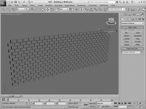
- Drag over both blocks to select them, and choose the Tools Array menu. In the Array dialog box that opens, set the 1D Count to 24 and the 2D Count to 8. Then enable the Preview button to see the changes, and drag the spinner next to the Incremental X value until the blocks are horizontally positioned next to each other. Then do the same for the Incremental Row Z value, and click OK.
The castle wall is complete and ready to go, as shown in Figure QS.1.
FIGURE QS.1 The wall was quickly created using the Array dialog box.
Tutorial: Gathering models
The wall looks great, but we need to dress up the scene a little. Using the Merge command, we can pull some models into the current scene. This also involves scaling them so they are the right size relative to each other.
To load the models, follow these steps:
- Use the Application Button Import Merge menu command, and locate the Turret and trees.max file from the Quick Start directory on the CD. In the Merge dialog box, select the All button and click OK.
- The turret model is loaded right in the middle of the scene and consists of a single part. We need to scale the turret and move it to the side of the wall.
- Click the turret to select it, and then select the Scale tool. Then drag the top handle only to scale it in the Z-direction. Then move it in the Front viewport using the Move tool so it lines up with the left side of the wall and its base it even with the base of the wall. Then move it in the Left viewport until it is centered and overlaps the wall.
- With the turret still selected, press and hold the Shift key and drag the turret to the right to create another turret positioned at the right edge of the wall. In the Clone Options dialog box, select the Copy option and click OK.
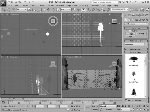
- Select the Create AEC Objects Foliage menu command, and click the Foliage button. Then select the Generic Palm, and click in the Top viewport to create four trees. Use the Scale tool to increase their size along the Z-axis.
Turrets now stand on either side of the wall, and some trees add to the scene, as shown in Figure QS.2.
FIGURE QS.2 The loaded turrets make the wall seem stronger.
Tutorial: Adding a ground plane
With the turret model loaded, we next add a ground plane to the scene. This can be a simple plane object, and we want to apply a Noise modifier to give it some bumps.
To add a ground plane, follow these steps:
- Click the Top viewport, and zoom out. Select the Plane button in the Command Panel to the right, and drag from the upper-left corner to the lower-right corner in the Top viewport to create a large plane object.
- In the Create panel, set the Length Segs and Width Segs to 30 to increase the plane's polygon density.
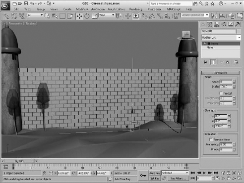
- With the plane object still selected, choose the Modifiers Parametric Deformers Noise menu command to apply a Noise modifier to the plane object. In the Parameters rollout, set the Scale value to 100 and the Z Strength value to 200.
The ground plane with a Noise modifier creates a nice landscape of rolling hills, as shown in Figure QS.3.
FIGURE QS.3 The scene now has a ground plane of rolling hills.
Adding Materials and Lights
The modeling phase, which usually is quite time-consuming, went really quickly when we used the Array dialog box and existing models. The next phase is to add materials to the models and lights to the scene. Because some of the models have applied materials already, this phase also goes pretty quickly.
Tutorial: Adding materials
After the modeling is complete, you can add materials to the objects to improve their look. Materials are added using the Material Editor, which is opened using the Rendering ![]() Material Editor
Material Editor ![]() Slate Material Editor menu command or by pressing the M keyboard shortcut.
Slate Material Editor menu command or by pressing the M keyboard shortcut.
Max 2012 includes a special set of procedural materials called Substance materials that are created using small bits of code instead of bitmaps.
To add materials to the wall and ground plane, follow these steps:
- Select the Rendering Material Editor Slate Material Editor menu command (or press the M key) to open the Material Editor. Locate and double-click the Standard material in the Material/Map Browser and also the Substance map in the Maps category.
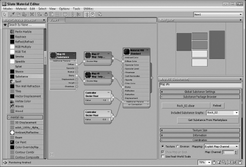
- Double-click the Substance node, and click the Load Substance button in the Substance Package Browser rollout of the Material Editor. In the textures folder, locate and load the Desert Sand 01 texture, and connect the Diffuse and Bump channels of the Substance node to the Standard node.
- With the ground plane selected in the viewports and the Standard material node selected in the Material Editor, click the Assign Material to Selection button in the toolbar of the Material Editor. This applies the material to the selected object.
- Click the Select by Name button on the main toolbar. Press and hold the Shift key, and click the first and last Box objects to select all the block objects in the scene.
- Repeat Steps 2 and 3 in the Material Editor, and apply the Rock 02 Substance texture to the scene blocks.
The rest of the models have materials already, so we can move on to lights. Figure QS.4 shows the Slate Material Editor.
FIGURE QS.4 The Material Editor lets you configure and apply materials to scene objects.
Tutorial: Adding a Sun & Sky system
One benefit of having the mental ray renderer enabled is that you also can use the Sun & Sky system. This system simulates outdoor lighting from a distant source like the sun and generates a sky for the background.
To add a Sun & Sky system to the scene, follow these steps:
- Select the Rendering Render Setup menu command (or press F10) to open the Render Setup dialog box. At the very bottom of the Common panel is the Assign Renderer rollout. Within this rollout, click the button to the right of the Production Renderer and double-click the mental ray Renderer option in the Choose Renderer dialog box that opens. Then close the Render Setup dialog box.
- Select the Create Lights Daylight System menu command, and drag in the Top viewport to add a compass helper to the scene. Click Ok to the request to enable the Exposure Control warning dialog box. Then click and drag to position the Sun light icon in the Top viewport.
Note
When the Daylight system is applied, a dialog box automatically appears recommending that you use the Logarithmic Exposure Control and asking whether you want to make this change. Click Yes to continue.
- Select the Rendering Environment menu command (or press the 8 key) to open the Environment and Effects dialog box. Click the Environment Map button, and select the mr Physical Sky map from the Maps/mental ray folder in the Material/Map Browser. Then enable the Use Map option, and close the Environment dialog box.
- Choose the Views Viewport Background Viewport Background menu command (or press Alt+B) to open the Viewport Background dialog box. Select the Perspective viewport, enable the Use Environment Background and the Display Background options, and close the dialog box.
- Click the Maximize Viewport button in the lower-right corner of the interface (or press Alt+W) to make the Perspective viewport full-sized.
- With the daylight light selected, click the Setup button in the Daylight Parameters rollout found in the Modify panel. Then set the Time Hours to 11. This sets the time of day to late afternoon.
- To see the lights and shadows in the viewport, click the viewport shading label in the upper-left corner of the viewport and select the Lighting and Shadows Illuminate with Scene Lights menu command (or press Shift+F3). Then turn on Shadows and Ambient Occlusion in the same Lighting and Shadows menu.
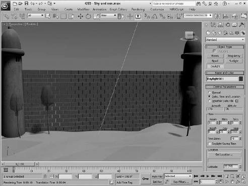
The viewport now shows the scene with a background sky, as shown in Figure QS.5.
FIGURE QS.5 The sky background is visible within the viewport.
Tutorial: Rendering a preview
Before moving to animation, you can render the scene now that lights have been added. Rendering is configured using the Render Scene dialog box.
To render a preview of the castle wall scene, follow these steps:
- Select the Rendering Render menu command (or press the F10 key), and open the Indirect Illumination panel. Turn on the Enable Final Gather option, and set the Preset to Medium. This computes a global illumination model by determining how light rays bounce about the scene.
- Back in the Common panel of the Render Scene dialog box, select the image size in the Common Parameters rollout and click the Render button. The active viewport is rendered and displayed in the Render Frame Window.
Tip
This scene is fairly simply and renders quickly, but if you need the test render to be even faster, you can enable the Quicksilver Hardware Renderer instead of the mental ray.
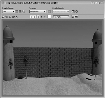
The rendered image, as shown in Figure QS.6, includes all the materials and lighting effects.
FIGURE QS.6 The rendered image of the scene includes the lighting effects.
Creating a Dynamic Animation with MassFX
With the test render complete and the scene looking good, we can move to the animation phase. This phase relies on the MassFX tools to create a dynamic animation.
Tutorial: Running a simulation
The first step in creating a dynamic animation with MassFX is to select and define all the pieces that will be included in the simulation; then we can run the simulation and see how it looks.
To set up the simulation using MassFX, follow these steps:
- We still need a projectile, so create a simple sphere object and position it about mid-wall height and set its color to black to look like a cannonball.
- Open the MassFX toolbar by right-clicking the main toolbar and selecting MassFX from the pop-up menu.
- Use the Select by Name button on the main toolbar to select all the blocks and the sphere object, and then click the Set Selected as Dynamic Rigid Body button in the MassFX toolbar.
- Select and zoom in on the cannonball in the Left viewport. In the Modify panel, expand the MassFX Rigid Body modifier and select the Initial Velocity option. In the Advanced rollout, set the Speed value to 5000 and X value of Initial Velocity to −180. Also in the Physical Material rollout, set the Density of the cannonball to 5.5.
Tip
If you find that the cannonball moves parallel to or away from the wall, adjust the Initial Velocity for another axis and try again.
- Press the Start Simulation button on the MassFX toolbar, and the cannonball crashes into the wall causing the blocks to fall.
- Click the Time Configuration button below the Play button, and set the End Time value to 350. This gives the scene more frames for the simulation.
- Select all the blocks and the sphere, and in the MassFX Tools dialog box, click the Bake Selected button to create animation keys for the most recent simulation.
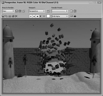
Figure QS.7 shows the castle wall after the cannonball has crashed through.
FIGURE QS.7 The broken wall after the cannonball has crashed through
Tutorial: Rendering the final animation
After the simulation looks good in the viewport, you are ready to render the final animation. This is a process that you can start by specifying the animation format. Once started, Max automatically proceeds through all the frames of the animation and notifies you when it is completed.
To render the final animation, follow these steps:
- Select the Rendering Render Setup menu command to open the Render Setup dialog box.
- At the top of the dialog box, enable the Active Time Segment so that all 350 frames of the animation will be rendered. Then set the Output Size to 640×480.
- In the Render Output section, click the Files button to open a File dialog box. Set the format as AVI, give the file a name such as Crashing Wall, and click the Save button. In the AVI Compression Setup dialog box that appears, simply select the default and click OK.
- At the very bottom of the Render Setup dialog box, make sure the Perspective view is selected and click the Render button.
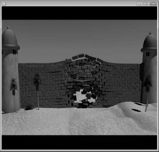
Max then renders each frame of the animation and shows its progress in a dialog box. When completed, the final animation file is saved with the filename you entered. You then can locate and play it. Figure QS.8 shows a frame of the final animation.
FIGURE QS.8 The final animation includes rendered results of each frame.
Summary
I hope you're happy with your first footsteps into Max. This chapter exposed you to a number of important aspects of Max, including the following:
- Setting up a scene
- Using the Array dialog box
- Applying materials to scene objects
- Enabling mental ray
- Using the Sun & Sky system, and enabling lights and shadows in the viewport
- Running dynamic simulations using MassFX
- Rendering the final animation
But hold onto your seats, because so much of the software lies ahead. In Chapter 1, you start easily with an in-depth look at the Max interface. If you feel ready for more advanced challenges, review the Table of Contents and dive into any topic that looks good.