
CHAPTER 37
Working with the F-Curve Editor in the Track View
Learning the Track View interface
Understanding the Track View Curve Editor and Dope Sheet layouts
Working with keys and time ranges
Adjusting function curves
Filtering tracks
Assigning controllers
Optimizing animation keys
Using out-of-range types
Adding notes to a track
Synching animation to a sound track
As you move objects around in a viewport, you often find yourself eyeballing the precise location of an object in the scene. If you've ever found yourself wishing that you could precisely see all the values behind the scene, then you need to find the Track View. The Track View can be viewed using three different layouts: Curve Editor, Dope Sheet, and Track Bar. Each of these interfaces offers a unique view into the details of the scene.
These Track View layouts can display all the details of the current scene, including all the parameters and keys. This view lets you manage and control all these parameters and keys without having to look in several different places.
The Track View also includes additional features that enable you to edit key ranges, add and synchronize sound to your scene, and work with animation controllers using function curves.
Learning the Track View Interface
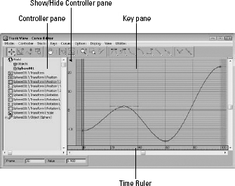
Although the Track View can be viewed using different layouts, the basic interface elements are the same. They all have menus, toolbars, a Controller pane, a Key pane, and a Time Ruler. Figure 37.1 shows these interface elements. You can hide any of these interface elements using the Show UI Elements option in the pop-up menu that appears when you right-click the title bar. Also, you can quickly hide the Controller pane by clicking the triangle icon in the upper-left corner of the Key pane.
New Feature
The Show/Hide Controller pane button is new to 3ds Max 2012.
FIGURE 37.1 The Track View interface offers a complete hierarchical look at your scene.
The Track View layouts
The Track View includes three different layouts: a Curve Editor, a Dope Sheet, and the Track Bar. The Curve Editor layout displays all parameter and motion changes as graphs that change over time. You manipulate these curves just like normal splines. You can use the Dope Sheet layout to coordinate key ranges between the different parameter tracks. And the Track Bar layout offers a way to quickly view the Track View within the viewports.
You can open the Curve Editor and Dope Sheet layouts using the Graph Editors menu. You can open the Curve Editor window by choosing Graph Editors ![]() Track View–Curve Editor or by clicking the Curve Editor button on the main toolbar. You open the Dope Sheet interface in a similar manner by choosing Graph Editors
Track View–Curve Editor or by clicking the Curve Editor button on the main toolbar. You open the Dope Sheet interface in a similar manner by choosing Graph Editors ![]() Track View–Dope Sheet.
Track View–Dope Sheet.
Cross-Reference
You also use the Graph Editors menu to access the Schematic View interface. For more on the Schematic View interface, see Chapter 25, “Building Complex Scenes with Containers, XRefs, and the Schematic View.”
After the Track View opens, you can give it a unique name using the Track View–Curve Editor field found on the Name: Track View toolbar. If the Name toolbar isn't visible, right-click the title bar and select Show Toolbars ![]() Name: Track View from the pop-up menu. These named views are then listed in the Graph Editors
Name: Track View from the pop-up menu. These named views are then listed in the Graph Editors ![]() Saved Track Views menu. Any saved Track Views that are named are saved along with the scene file.
Saved Track Views menu. Any saved Track Views that are named are saved along with the scene file.
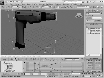
To open the Track Bar layout in the viewports, expand the Track Bar using the Open Mini Curve Editor button at the left end of the Timeline. Close the Track Bar layout by clicking the Close button on the toolbar. Figure 37.2 shows this Track View.
After you open a Track View, you can switch between the Curve Editor and the Dope Sheet using the Modes menu or by right-clicking the menu bar or toolbar (away from the buttons) and selecting a new layout from the Load Layout menu. You can also save customized layouts using the Save Layout or Save Layout As menu commands.
FIGURE 37.2 The Track Bar offers quick access to the Track View.
Track View menus and toolbars
In many cases, the menus and the toolbars provide access to the same functionality. One difference is the Modes menu, which lets you switch the current interface between the Curve Editor and the Dope Sheet layouts. The Curve Editor menus include Modes, Controller, Tracks, Keys, Curves, Options, Display, View, and Utilities. The Dope Sheet menu loses the Curves menus and adds a Time menu in its place. The Track Bar menus are the same as the Curve Editor menus, except that the Modes menu is absent.
The Track View consists of several toolbars. You can open these toolbars by right-clicking the toolbar (away from the buttons) and selecting the Show Toolbars submenu. The available toolbars depend on the layout (Function Curve Layout, Function Curve Layout [Classic], or Dope Sheet). The default Function Curve toolbars are the Key Controls, Navigation, Key Tangents, Tangent Actions, and Key Entry. For the Track View–Dope Sheet, the default toolbars at the top of the interface include the Keys, Time, Display, and Name toolbars. All these toolbars can be docked, floated, and hidden. You also can add and delete new toolbars using the right-click pop-up menu.
New Feature
The Key Controls, Key Entry, and Tangent Actions toolbars are all new to 3ds Max 2012.
Cross-Reference
You can learn more about docking and floating toolbars in Chapter 1, “Exploring the Max Interface.”
For the Function Curve Editor, these toolbars are a reduced set that includes the main functions. The older toolbars are still available and can be selected using the Load Layout ![]() Function Curve Layout (Classic) menu command in the toolbar right-click pop-up menu.
Function Curve Layout (Classic) menu command in the toolbar right-click pop-up menu.
Depending on the size of the Track View window, you may need to drag the toolbar to the left to see the buttons at the right end of the toolbar.
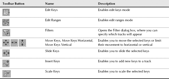
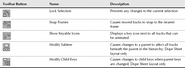
Key Controls toolbar
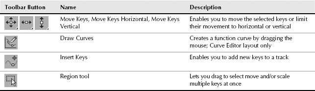
The Key Controls toolbar is the first of the default toolbars for the Function Curve Editor. Table 37.1 describes these buttons.
TABLE 37.1 Key Controls Toolbar Buttons
Navigation toolbar
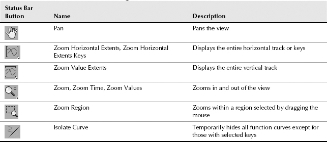
The Navigation toolbar for the Curve Editor lets you pan and zoom to focus on a specific area of the Track View window. Table 37.2 describes these buttons. This same toolbar is available in the Dope Sheet.
TABLE 37.2 Navigation Toolbar Buttons
Key Tangents toolbar
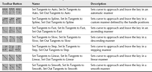
The Key Tangents toolbar is another of the default Curve Editor toolbars. It is used to set the In and Out curve types. This toolbar also is available in the Dope Sheet layout. Table 37.3 describes these buttons.
TABLE 37.3 Key Tangents Toolbar Buttons
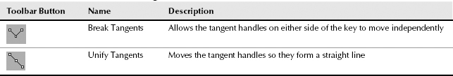
Tangent Actions toolbar
The Tangent Actions toolbar is another of the default toolbars in the Curve Editor. It is used to quickly break and unify tangent handles. Table 37.4 describes these buttons.
TABLE 37.4 Tangent Actions Toolbar Buttons
Key Entry toolbar
The Key Entry toolbar in the Curve Editor displays the current frame and value for the selected key. If multiple keys are selected, only the frame value is displayed. You also can enter values in these fields to change the current frame and/or value for the selected key or keys. This is a huge timesaver if you want to change multiple keys to the same value.
The same frame and value fields are available in the Dope Sheet in the Key Stats toolbar.
Key Tangents toolbar
The Key Tangents toolbar is the first of the default toolbars in the Dope Sheet. Table 37.5 describes these buttons.
TABLE 37.5 Key Tangents Toolbar Buttons
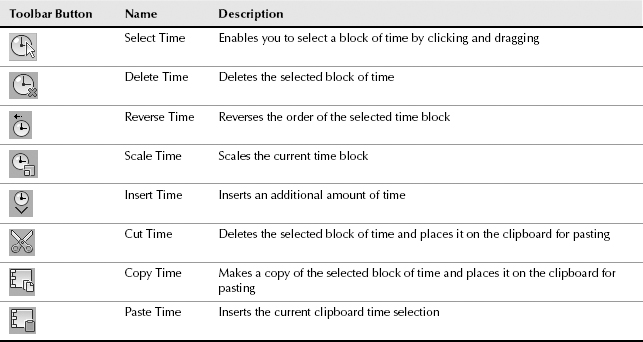
Time toolbar
The Time toolbar is another of the default toolbars for the Dope Sheet. It is used to work with time ranges. Table 37.6 describes these buttons.
TABLE 37.6 Time Toolbar Buttons
Display toolbar
The Display toolbar is another of the default toolbars for the Dope Sheet. Table 37.7 describes these buttons.
TABLE 37.7 Display Toolbar Buttons
Track Selection toolbar
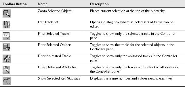
At the bottom edge of the Dope Sheet window are three toolbars that appear by default. These toolbars are the Track Selection, Key Stats, and Navigation. Using these toolbars, you can locate specific tracks, see information on the various keys, and navigate the interface.
In the Track Selection toolbar is the Zoom Selected Object button and the Select by Name field, in which you can type a name to locate any tracks with that name.
Note
In the Select by Name field, you also can use wildcard characters such as * (asterisk) and ? (question mark) to find several tracks.
The Key Stats toolbar includes Key Time and Value Display fields that display the current time and value. You can enter values in these fields to change the value for the current time. You also can enter an expression in these fields in which the variable n equals the key time or value. For example, to specify a key value that is 20 frames from the current frame, enter n+20 (where you supply the current value in place of n). You also can include any function valid for the Expression controller, such as sin( ) or log( ). Click the Show Selected Key Stats button to display the key value in the Key pane.
Cross-Reference
Chapter 22, “Animating with Constraints and Simple Controllers,” presents the functions that are part of the Expression controller.
Table 37.8 describes the buttons found in the Track Selection and Key Stats toolbars.
TABLE 37.8 Track Selection and Key Stats Toolbar Buttons
Other toolbars
The other toolbars provide access to features that also are available through the menus. These toolbars are hidden by default, but they can be made visible using the Show Toolbars menu command in the right-click pop-up menu.
Controller and Key panes
Below the menus (and below the topped docked toolbars) are two panes. The left pane, called the Controller pane, presents a hierarchical list of all the tracks. The right pane is called the Key pane, and it displays the time range, keys, or function curves, depending on the layout. You can pan the Controller pane by clicking and dragging on a blank section of the pane: The cursor changes to a hand to indicate when you can pan the pane.
Tip
Using the triangle icon in the upper-left corner of the Key pane, you can quickly hide the Controller pane.
Each track can include several subtracks. To display these subtracks, click the plus sign (+) to the left of the track name. To collapse a track, click the minus sign (–). You can also use the Settings menu to Auto Expand a selected hierarchy. Under the Options ![]() Auto Expand menu are options for Selected Objects Only, Transforms, XYZ Components, Limits, Keyable, Animated, Base Objects, Modifiers, Materials, and Children. For example, if the Auto Expand
Auto Expand menu are options for Selected Objects Only, Transforms, XYZ Components, Limits, Keyable, Animated, Base Objects, Modifiers, Materials, and Children. For example, if the Auto Expand ![]() Transforms option is enabled, then the Transform tracks for all objects is automatically expanded in the Track View. Using these settings can enable you to quickly find the track you're looking for.
Transforms option is enabled, then the Transform tracks for all objects is automatically expanded in the Track View. Using these settings can enable you to quickly find the track you're looking for.
The Options ![]() Auto Select
Auto Select ![]() Animated toggle automatically selects all tracks that are animated. You can also auto select Position, Rotation, and/or Scale tracks. The Options
Animated toggle automatically selects all tracks that are animated. You can also auto select Position, Rotation, and/or Scale tracks. The Options ![]() Auto Scroll menu command can be set for Selected and/or Objects tracks. This command automatically moves either the Selected tracks or the Objects track to the top of the Controller pane.
Auto Scroll menu command can be set for Selected and/or Objects tracks. This command automatically moves either the Selected tracks or the Objects track to the top of the Controller pane.
Note
You can also select, expand, and collapse tracks using the right-click pop-up quadmenu.
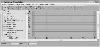
The Controller pane includes many different types of tracks. By default, every scene includes the following tracks: World, Sound, Video Post, Global Tracks, SME, Anim Layer Control Manager, Environment, Render Effects, Render Elements, Renderer, Global Shadow Parameters, Scene Materials, Medit Materials (for materials in the Material Editor), and Objects, as shown in Figure 37.3.
FIGURE 37.3 Several tracks are available by default.
The Shift, Ctrl, and Alt keys make selecting and deselecting multiple tracks possible. To select a contiguous range of tracks, select a single track and then select another track while holding down the Shift key. This selects the two tracks and all tracks in between. Hold down the Ctrl key while selecting tracks to select multiple tracks that are not contiguous. The Alt key removes selected items from the selection set.
Below the right pane is the Time Ruler, which displays the current time as specified in the Time Configuration dialog box. The current frame is marked with a light blue time bar. This time bar is linked to the Time Slider, and moving one updates the other automatically.
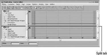
At the top right of the Key pane (above the vertical scroll bar) is a split tab that you can use to split the Controller and Key pane into two separate views, as shown in Figure 37.4. Using this feature, you can look at two different sections of the tree at the same time. This makes it easy to copy and paste keys between different tracks.
Tip
You can drag the Time Ruler vertically in the right pane.
FIGURE 37.4 Drag the tab above the vertical scroll tab to split the Track View into two views.
Working with Keys
Keys define the main animation points in an animation. Max interpolates all the positions and values between the key points to generate the animation. Using the Track View, you can edit these animation keys with precision. Keys can be edited in either layout but are probably easiest to edit in the Dope Sheet layout with the Edit Keys button enabled.
Cross-Reference
Chapter 21, “Understanding Animation and Keyframes,” covers key creation in more detail.
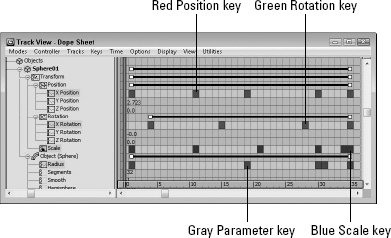
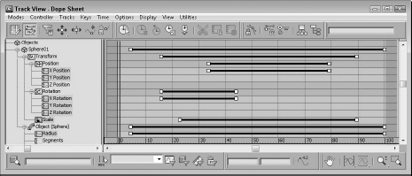
In the Curve Editor, keys are shown as small squares positioned along the curve. In the Dope Sheet, keys are shown as colored lines that extend across the applicable tracks, as shown in Figure 37.5. The keys for the Position track are red, the Rotation track keys are green, the Scale track keys are blue, and the Parameter tracks (all non-transformation keys) are gray. Parent tracks (such as an object's name) are colored gray. Selecting a parent key selects all its children keys. Any selected keys appear white. A track title that includes a key is highlighted yellow.
Caution
If the Key pane is not wide enough, then a key is shown as a thick, black line.
FIGURE 37.5 In the Dope Sheet, Position keys are red, Rotation keys are green, Scale keys are blue, and Parameter keys are gray.
Selecting keys
Before you can move and edit keys, you need to be able to select them. Just like selecting keys on the Track Bar, you select keys by clicking them. Selected keys turn white. To select multiple keys, hold down the Ctrl key while clicking several keys, or drag an outline over several keys to select them. Click away from the keys to deselect all the selected keys.
With a key or multiple keys selected, you can lock the selection with the Lock Selection button. The spacebar is the keyboard shortcut for this button. With the selection locked, you cannot select any new keys.
Tip
If you want to access a specific parameter in the Track View, you can right-click the parameter and select the Show in Track View command from the pop-up menu, and the Track View loads with the parameter visible.
Using soft selection
The Keys menu also includes a Use Soft Select option. This feature is similar to the soft selection found in the Modify panel when working on a subobject, except that it works with keys causing adjacent keys to move along with the selected keys, but not as much. The Keys ![]() Soft Select Settings menu command opens a simple toolbar where you can enable soft selection and set the Range and Falloff values.
Soft Select Settings menu command opens a simple toolbar where you can enable soft selection and set the Range and Falloff values.
When enabled, all keys within a specified range are also selected and moved to a lesser degree than the selected key. When enabled, the function curve is displayed with a gradient for the Curve Editor layout and as a gradient across the key markers in the Dope Sheet layout. This shows the range and falloff for the curve.
The Keys ![]() Soft Select Settings menu opens a hidden toolbar that lets you enable and disable the soft selection feature with a single button labeled Soft. The Range value sets how many frames the soft selection covers. This toolbar may be docked to the edge of the window.
Soft Select Settings menu opens a hidden toolbar that lets you enable and disable the soft selection feature with a single button labeled Soft. The Range value sets how many frames the soft selection covers. This toolbar may be docked to the edge of the window.
Adding and deleting keys
You can add a key by clicking the Insert Keys button (or pressing the A key) and clicking the location where the new key should appear. Each new key is set with the interpolated value between the existing keys. This can be done whether the Auto Key button at the bottom of the Max interface is on or off.
To delete keys, select the keys and press the Delete key on the keyboard. If a key is deleted, the function curve changes to account for the missing key.
Moving, sliding, and scaling keys
The Move Keys button (keyboard shortcut M) lets you select and move a key to a new location. You can clone keys by pressing and holding the Shift key while moving a key. Using the flyout buttons, you can select to restrict the movement horizontally or vertically. You also can move the selected key to the cursor's location (the current frame) with the Keys ![]() Align to Cursor menu command.
Align to Cursor menu command.
The Slide Keys button in the Dope Sheet lets you select a key and move all adjacent keys in unison to the left or right. If the selected key is moved to the right, all keys from that key to the end of the animation slide to the right. If the key is moved to the left, then all keys to the beginning of the animation slide to the left.
The Scale Keys button, also in the Dope Sheet, lets you move a group of keys closer together or farther apart. The scale center is the current frame. You can use the Shift key to clone keys while dragging.
If the Dope Sheet's Snap Frames button (keyboard shortcut S) is enabled, the selected key snaps to the nearest key as it is moved. This makes aligning keys to the same frame easy.
Using the Region tool
Within the Curve Editor, the Region tool is used to move, slide, and scale a set of selected keys. To use this tool, simply drag in the Key pane over the keys you want to select. A box is displayed around all the selected keys with handles at each edge, as shown in Figure 37.6. The selected keys can be moved to a different location by clicking within the region and dragging to a new location. You can drag the selected keys up or down to change their values or left and right to change their frame.
New Feature
The Region tool is new to 3ds Max 2012.
FIGURE 37.6 The Region tool places handles around each side of the selected keys for sliding and scaling keys.
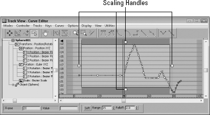
Dragging on either of the side handles scales the range of the selected keys, and dragging on the top or bottom handles scales their values. The side of the selected handle is the side of the region that moves during a scale operation, but if you press and hold the Shift key, the region is scaled equally from both sides. If you scale the region over any non-selected keys, those non-selected keys are simply deleted. The Region tool remains active until another tool, such as the Move tool is selected. If you click and drag outside of the selected region, a new region is selected.
Editing keys
To edit the key parameters for any controller, right-click the key in the Curve Editor or click the Properties button in the Dope Sheet; this opens the Key Info dialog box for most controllers. You also can access this dialog box by right-clicking a track and selecting Properties from the pop-up menu. These commands also can be used when multiple keys on the same or on different tracks are selected.
Using the Randomize Keys utility
The Randomize Keys utility lets you generate random time or key positions with an offset value. To access this utility, select the track of keys that you want to randomize and choose Utilities ![]() Track View Utilities to open the Track View Utilities dialog box. From this dialog box, select Randomize Keys from the list of utilities and click OK; the Randomize Keys utility dialog box opens, as shown in Figure 37.7.
Track View Utilities to open the Track View Utilities dialog box. From this dialog box, select Randomize Keys from the list of utilities and click OK; the Randomize Keys utility dialog box opens, as shown in Figure 37.7.
FIGURE 37.7 Use the Randomize Keys utility to create random key positions and values.
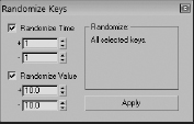
In this dialog box, you can specify positive and negative shift values for both Time and Value. Click the Apply button to apply the randomization process.
Using the Euler Filter utility
Euler rotations are easy to understand and use. They provide rotations about each of the three axes or can be thought of as yaw, pitch, and roll, but they have an inherit flaw—they are susceptible to Gimbal flipping and Gimbal lock. Gimbal flipping can occur when the rotation is directed straight up or straight down. This causes the object to instantly flip 180 degrees to continue its rotation. Gimbal lock can occur when two Euler rotation angles are aligned, causing the object to lose a degree of freedom.
To counter these problems, Max has the ability to use Quaternions instead of Euler angles. Quaternions are vector-based instead of angle-based, so they aren't susceptible to the Gimbal flipping and lock problems, but many animators find Quaternions difficult to understand and use, so they stick to Euler rotations and are watchful for potential problems.
The Track View has a utility that can help if you're dealing with Euler rotations. The Euler Filter utility analyzes the current frame range and corrects any Gimbal flipping that it detects. Selecting this utility from the Track View Utilities dialog box opens a simple dialog box where you can set the range to analyze. You also have an option to Insert Keys if Needed.
Displaying keyable icons
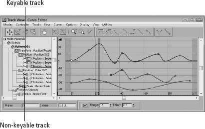
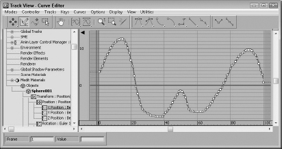
If you're not careful, you could animate a track that you didn't mean to (especially with the Auto Key mode enabled). By marking a track as non-keyable or keyable, you can control which tracks can be animated. To do this, choose the Display ![]() Keyable Icons menu. This places a small red key icon to the left of each track that can be animated. You can then click the icon to change it to a non-keyable track. Figure 37.8 shows the Curve Editor with this feature enabled.
Keyable Icons menu. This places a small red key icon to the left of each track that can be animated. You can then click the icon to change it to a non-keyable track. Figure 37.8 shows the Curve Editor with this feature enabled.
FIGURE 37.8 The Keyable Icons feature displays an icon next to all tracks that can be keyed.
Editing Time
In some cases, directly working with keys isn't what you want to do. For example, if you need to change the animation length from six seconds to five seconds, you want to work in the Dope Sheet's Edit Ranges mode. To switch to this mode, click the Edit Ranges button on the Key Tangents toolbar. In this mode, the key ranges are displayed as black lines with square markers on either end, as shown in Figure 37.9.
FIGURE 37.9 Click the Edit Ranges button to display the key ranges in the Key pane.
Selecting time and the Select Keys by Time utility
Before you can scale, cut, copy, or paste time, you need to select a track and then select a time block. To select a section of time, click the Select Time button and drag the mouse over the time block.
The Select Keys by Time utility lets you select all the keys within a given time block by entering the frame or time values. To use this utility, click the Track View Utilities button or select the Utilities ![]() Track View Utilities menu command to open the Track View Utilities dialog box, and choose the Select Keys by Time utility from the list. Then in the Select Keys by Time dialog box, enter the Start and End values to complete the selection.
Track View Utilities menu command to open the Track View Utilities dialog box, and choose the Select Keys by Time utility from the list. Then in the Select Keys by Time dialog box, enter the Start and End values to complete the selection.
Deleting, cutting, copying, and pasting time
After you select a block of time, you can delete it by clicking the Delete Time button. Another way to delete a block of time is to use the Cut Time button, which removes the selected time block but places a copy of it on the clipboard for pasting. The Copy Time button also adds the time block to the clipboard for pasting, but it leaves the selected time in the track.
After you copy a time block to the clipboard, you can paste it to a different location within the Track View. The track where you paste it must be of the same type as the one from which you copied it.
All keys within the time block are also pasted, and you can select whether they are pasted relatively or absolutely. Absolute pasting adds keys with the exact values as the ones on the clipboard. Relative pasting adds the key value to the current initial value at the place where the key is pasted.
You can enable the Exclude Left End Point and Exclude Right End Point buttons on the Extras toolbar when pasting multiple sections next to each other. By excluding either end point, the time block loops seamlessly.
Reversing, inserting, and scaling time
The Reverse Time button flips the keys within the selected time block.
The Insert Time button lets you insert a section of time anywhere within the current track. To insert time, click and drag to specify the amount of time to insert; all keys beyond the current insertion point slide to accommodate the inserted time.
The Scale Time button scales the selected time block. This feature causes all keys to be pushed closer together or farther apart. The scaling takes place around the current frame.
Setting ranges
The Position Ranges button on the Ranges toolbar enables you to move ranges without moving keys. In this mode, you can move and scale a range bar independently of its keys, ignoring any keys that are out of range. For example, this button, when enabled, lets you remove the first several frames of an animation without moving the keys. The Recouple Ranges button can be used to line up the keys with the range again. The left end of the range aligns with the first key, and the right end aligns with the last key.
Editing Curves
When an object is moving through the scene, estimating the exact point where its position changes direction can sometimes be difficult. Function curves provide this information by presenting a controller's value as a function of time. The slope of the function curve shows the value's rate of change. Steep curves show quick movements. Shallow lines are slow-moving values. Each key is a vertex in the curve. Function curves are visible only in the Curve Editor and the Track Bar layout.
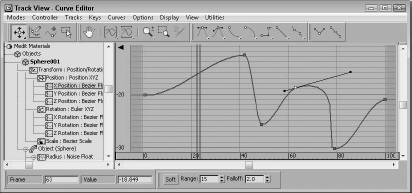
Function curves mode lets you edit and work with these curves for complete control over the animation parameters. Figure 37.10 shows the Position curves for a sphere that moves about the scene.
FIGURE 37.10 Function curves display keys as square markers along the curve.
Inserting new keys and moving keys
Function curves with only two keys have slow in and out tangents, making the animation start slow, speed up, and then slow down. You can add more curvature to the line with the addition of another key. To add another key, click the Insert Keys button, and then click the curve where you want to place the key.
Tip
Keep the total number of keys to a minimum. More keys make editing more difficult.
If the curve contains multiple curves, such as a curve for the Position or RGB color values, then a point is added to each curve. The Move Keys button enables you to move individual keys by dragging them. It also includes flyouts for constraining the key movement to a horizontal or vertical direction.
To scale keys, use the Region tool; you also could use the Keys ![]() Scale Keys–Time command to move the selected keys toward or away from the current time. The keys move only horizontally. The Keys
Scale Keys–Time command to move the selected keys toward or away from the current time. The keys move only horizontally. The Keys ![]() Scale Values command is used to move the selected keys toward or away from the zero value. The keys move only vertically.
Scale Values command is used to move the selected keys toward or away from the zero value. The keys move only vertically.
Tutorial: Animating a monorail
As an example of working with function curves, you'll animate a monorail that moves around its track, changing speeds, and stopping for passengers.
To animate the monorail using function curves, follow these steps:
- Open the Monorail.max file from the Chap 37 directory on the CD.
This file contains a simple monorail setup made from primitives.
- Click the Play button, and watch the train move around the track.
As a default, the Path Constraint's Percent track has a Linear controller that causes the train to move at a constant speed. To refine the animation, you need to change it.
- Open the Track View–Curve Editor by first selecting the train object in the scene and then right-clicking and choosing Curve Edit from the pop-up quadmenu. The Track View-Curve Editor window opens and shows the controls related to the object in the scene you have selected. Click the Assign Controller button or right-click and select Assign Controller from the pop-up menu to open the Assign Float Controller dialog box. Select the Bézier Float controller, and click OK.
Note
If the Objects track isn't visible, open the Filter Tracks dialog box and make sure the Objects option is enabled.
- Click the Play button. The train starts slowly (represented by the flattish part of the curve), accelerates (the steeper part of the curve), and slows down again (another flattish part).
Tip
When “reading” function curves, remember that a steep curve produces fast animation, a shallow curve produces slow animation, a horizontal curve produces no movement or value change, and a straight curve produces a constant animation.
- You need the train to stop for passengers at the station, so click the Insert Keys button (or right-click and choose Insert Keys) and add a key somewhere around frame 115 when the train is near the dock.
- Select the newly created key, and choose the Move Keys Horizontal button from the Move Keys flyout. Hold down the Shift key, and drag right to copy the key to frame 135.
The curve is flat, so the train stops at the station.
- To adjust the actual position where the train stops, choose the Move Keys Vertical button from the Move Keys flyout, select both keys, and move them up or down until the train's position at the station is correct.
Because the default in and out tangent types cause the curve to flatten out at the keys, the train slows as it reaches the station and then starts out slow and picks up speed as it leaves the station. Anyone who has ever ridden on a train knows that stopping and starting are not always smooth operations. Next, you add a few more keys to make the train shudder to a stop and lurch as it starts out again.
- Click the Insert Keys button (or right-click and choose Insert Keys), and insert keys somewhere around frames 105, 109, 113, 142, and 150. Use Zoom Region to zoom in on the keys where the train pulls into the station to stop.
- Change the Move Keys Vertical button back to Move Keys by selecting it from the flyout, and move the keys slightly up or down to send the train backward and forward along the path.
- As you can see, a little movement goes a long way, so the keys need only to be offset a very small amount. Use the Zoom Values button from the Zoom flyout and the Pan button to help in making the small changes to the animation.
- Repeat for the keys where the train leaves the station.
The train also needs to slow down to look at one of the famous buildings in “Primitive Town,” the Tubular “building” on the far side of the track.
- Add a couple more keys somewhere around frames 18 and 50. Lower the second of the new keys until the curve is shallower but not horizontal. Again, adjust the train's position on the track (Percent along the path) by raising or lowering the two new keys.
- Adjust the Out tangent handle of the very first key and the In tangent handle of the very last key to produce a smooth looping animation.
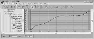
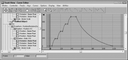
Figure 37.11 shows the final curve after you've completed the editing, and Figure 37.12 shows the monorail along its path.
FIGURE 37.11 The finished Percent curve for the train's position along the path
Drawing curves
If you know what the curve you want is supposed to look like, you can actually draw it in the Key pane with the Draw Curves button enabled. This mode adds a key for every change in the curve. You may want to use the Reduce Keys optimization after drawing a curve.
Tip
If you make a mistake, you can just draw over the top of the existing curve to make corrections.
Figure 37.13 shows a curve that was created with the Draw Curves feature.
FIGURE 37.12 The monorail and “Primitive Town”

FIGURE 37.13 Drawing curves results in numerous keys.
Reducing keys
The Keys ![]() Reduce Keys menu command enables you to optimize the number of keys used in an animation. Certain IK (inverse kinematics) methods and the Dynamics utility calculate keys for every frame in the scene, which can increase your file size greatly. By optimizing with the Reduce Keys command, you can reduce the file size and complexity of your animations.
Reduce Keys menu command enables you to optimize the number of keys used in an animation. Certain IK (inverse kinematics) methods and the Dynamics utility calculate keys for every frame in the scene, which can increase your file size greatly. By optimizing with the Reduce Keys command, you can reduce the file size and complexity of your animations.
Using the Reduce Keys command opens the Reduce Keys dialog box. The threshold value determines how close to the actual position the solution must be to eliminate the key. Figure 37.14 shows the same curve created with the Draw Curves feature after it has been optimized with a Threshold value of 0.5 using the Reduce Keys feature.
FIGURE 37.14 The Reduce Keys feature optimizes the curve by reducing keys.

Working with tangents
Function curves for the Bézier controller have tangents associated with every key. To view and edit these tangents, select the Display ![]() All Tangents menu command. These tangents are lines that extend from the key point with a handle on each end. By moving these handles, you can alter the curvature of the curve around the key.
All Tangents menu command. These tangents are lines that extend from the key point with a handle on each end. By moving these handles, you can alter the curvature of the curve around the key.
You can select the type of tangent from the Key Tangents toolbar. These can be different for the In and Out portion of the curve. You can also select them using the Key dialog box. The default tangent type for all new keys is set using the button to the left of the Key Filters button at the bottom of the Max interface. Using this button, you can quickly select from any of the available tangent types.
You open the Key dialog box, shown in Figure 37.15, by selecting a key and right-clicking the key. It lets you specify two different types of tangent points: Continuous and Discontinuous. Continuous tangents are points with two handles on the same line. The curvature for continuous tangents is always smooth. Discontinuous tangents have any angle between the two handle lines. These tangents form a sharp point.
By default, all tangents are continuous and move together, but you can break them apart to be discontinuous by clicking the Break Tangents button in the Tangent Actions toolbar. This lets each handle be moved independently. Broken tangents can be locked together again with the Unify Tangents button, so they move together. This unifies the tangent handles even if they don't form a straight line.
New Feature
The Break and Unify Tangents buttons are new to 3ds Max 2012.
Tip
Holding down the Shift key while dragging a handle lets you drag the handle independently of the other handle.
FIGURE 37.15 The Key dialog box lets you change the key's Time, Value, or In and Out tangent curves.
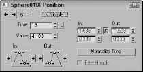
The Lock Tangents button in the Key Info dialog box lets you change the handles of several keys at the same time. If this button is disabled, adjusting a tangent handle affects only the key of that handle.
Tutorial: Animating a flowing river
The default auto-tangent types create a function curve that has ease-in and ease-out built into the curve. This causes the animation to start slowly, speed up, and then slow to a stop. While this may be a good starting point for many animations, it won't work for those that should have a constant speed. This example shows how to create a river with a material animated to a constant speed.
To create a flowing river, follow these steps:
- Open the River.max file from the Chap 37 directory on the CD.
This file contains a river surface made from a loft. The V Offset for the River Water material's diffuse channel has been animated to simulate flowing water (yes, this river has a checkered past . . .).
- Click the Play button.
The river flow starts out slow, speeds up, and then slows to a stop.
Note
The river flows using a checker texture map. Make sure to select a viewport with textures enabled to see the flowing effect.
- Open the Track View–Curve Editor, and locate and select the V Offset track for the river's material. (You can find this track under the Scene Materials
 River Water Maps Diffuse Color: Map #2 (Checker) Coordinates V Offset menu command.)
 - You have two easy options for creating an animation with a constant speed. The first changes the entire controller type; the second changes the individual key's tangent types.
Option 1: Right-click over the V Offset track and choose Assign Controller or choose Assign from Controller on the menu bar to open the Assign Float Controller dialog box. Select Linear Float, and click OK.
or
Option 2: Select both keys by clicking one key, holding down the Ctrl button, and clicking the other, or by dragging an outline around both keys. Click the Set Tangents to Linear button.
Whichever method you use, the line between the two keys is now straight.
- Click the Play button.
The river now flows at a constant speed.
- To increase the speed of the flow, select Move Keys Vertical from the Move Keys button flyout, and select and move the end key higher in the graph.
The river flows faster.
Figure 37.16 shows the river as it flows along.
Applying out-of-range, ease, and multiplier curves
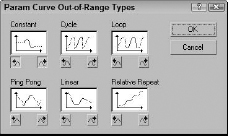
Out-of-range curves define what the curve should do when it is beyond the range of specified keys. For example, you could tell the curve to loop or repeat its previous range of keys. To apply these curves, select a track and select the Out-of-Range menu command from the Controller menu. This opens a dialog box, shown in Figure 37.17, where you can select from the available curve types.
FIGURE 37.16 The Checkered River flows evenly.
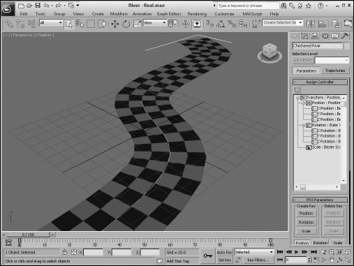
FIGURE 37.17 The Param Curve Out-of-Range Types dialog box lets you select the type of out-of-range curve to use.
Note
You can also apply an out-of-range curve to a select range of frames using the Create Out-of-Range Keys utility. This utility is available via the Track View Utilities menu.
By clicking the buttons below the types, you can specify a curve for the beginning and end. This Out-of-Range dialog box includes six options:
- Constant: Holds the value constant for all out-of-range frames
- Cycle: Repeats the track values as soon as the range ends
- Loop: Repeats the range values, like the Cycle option, except that the beginning and end points are interpolated to provide a smooth transition
- Ping Pong: Repeats the range values in reverse order after the range end is reached
- Linear: Projects the range values in a linear manner when out of range
- Relative Repeat: Repeats the range values offset by the distance between the start and end values
You can apply ease curves (choose Curves ![]() Apply Ease Curve, or press Ctrl+E) to smooth the timing of a function curve. You can apply multiplier curves (Curves
Apply Ease Curve, or press Ctrl+E) to smooth the timing of a function curve. You can apply multiplier curves (Curves ![]() Apply Multiplier Curve, Ctrl+M) to alter the scaling of a function curve. You can use ease and multiplier curves to automatically smooth or scale an animation's motion. Each of these buttons adds a new track and function curve to the selected controller track.
Apply Multiplier Curve, Ctrl+M) to alter the scaling of a function curve. You can use ease and multiplier curves to automatically smooth or scale an animation's motion. Each of these buttons adds a new track and function curve to the selected controller track.
Ease and Multiplier curves add another layer of control on top of the existing animation and allow you to edit the existing animation curves without changing the original animation keys. For example, if you have a standard walk cycle, you can use an ease curve to add a limp to the walk cycle or you can reuse the walk cycle for a taller character by adding a multiplier curve.
Note
Not all controllers can have an ease or multiplier curve applied.
You can delete these tracks and curves using the Curves ![]() Remove menu command. You also can enable or disable these curves with the Curves
Remove menu command. You also can enable or disable these curves with the Curves ![]() Enable Ease/Multiplier Curve Toggle menu command.
Enable Ease/Multiplier Curve Toggle menu command.
After you apply an ease or multiplier curve, you can assign the type of curve to use with the Ease Curve Out-of-Range Types button. This button opens the Ease Curve Out-of-Range Types dialog box, which includes the same curve types as the Out-of-Range curves, except for the addition of an Identity curve type.
Note
In the Ease Curve Out-of-Range Types dialog box is an Identity option that isn't present in the Parameter Curve Out-of-Range Types dialog box. The Identity option begins or ends the curve with a linear slope that produces a gradual, constant rate increase.
When editing ranges, you can make the range of a selected track smaller than the range of the whole animation. These tracks then go out of range at some point during the animation. The Ease/Multiplier Curve Out-of-Range Types buttons are used to tell the track how to handle its out-of-range time.
Tutorial: Animating a wind-up teapot
As an example of working with multiplier curves, you'll create a wind-up teapot that vibrates its way across a surface.
To animate the vibrations in the Track View, follow these steps:
- Open the Wind-up teapot.max file from the Chap 37 directory on the CD.
This file contains a teapot with legs.
- Click the Play button.
The teapot's key winds up to about frame 40 and then runs down again as the teapot moves around a bit. To add the random movement and rotation to make the vibrations, you use Noise controllers and Multiplier curves to limit the noise.
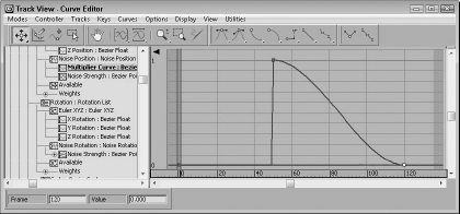
- Open the Track View–Curve Editor, and navigate down to the Wind-up Key's X Rotation track, located at Objects, Teapot Group, Key, Rotation: Euler XYZ, X Rotation. Take a moment to observe the shape of the curve, shown in Figure 37.18.
The key is “wound up” in short spurts and then runs down, slowing until it stops. The vibration, then, should start midway and then taper off as the key runs down.
FIGURE 37.18 The rotation of the Wind-up Key object
- Click the teapot in the viewport to have the curves for its transforms selected and centered in the Track View.
When adding the Noise controller, you should assign a List controller first to retain the ability to transform the object independently of the Noise.
Note
Assigning controllers through the Animation menu automatically creates a List controller first.
- Select the teapot's Position track, and click the C key to access the Assign Controller dialog box. Choose Position List. Under the Position track are now the X, Y, and Z Position tracks and an Available track. Select the Available track, access the Assign Controller dialog box again, and choose Noise Position. The default controller should remain the Position XYZ controller, so close the List Controller dialog box. Click Play.
Remember that the C keyboard shortcut works only if the Keyboard Shortcut Override Toggle button on the main toolbar is enabled.
The teapot vibrates the entire animation. You add a multiplier curve to correct the situation.
- Select the Noise Position track, and choose Curves Apply-Multiplier Curve. Select the Multiplier curve track. Assign the first key a value of 0. Change its Out tangent to Stepped so it holds its value until the next key. Click the Insert Keys button, and add a key at frame 50 with a value of 1. Move the last key to frame 120, and set a value of 0. The Multiplier curve should now look like the curve in Figure 37.19. Select the Noise Position track.
The noise curve now conforms to the multiplier track.
FIGURE 37.19 The Multiplier curve keeps the Noise track in check.
- With the Noise Position track still selected, right-click and choose Properties. In the Noise Position dialog box, set the X and Y Strength to 30, set the Z strength to 20, and check the >0 check box to keep the teapot from going through the floor. Close the dialog box, and click Play.
The animation is much better. Next, you add some noise to the Rotation track.
- Select the Rotation track, right-click, and choose Assign controller or click the C key to bring up the Assign Controller dialog box. Select Rotation List, and click OK. Select the Available track, access the Assign Controller dialog box again, and choose Noise Rotation.
Click Play. Again, the noise is out of control.
- This time, select the Noise Strength track and add a multiplier curve.
You already have a perfectly good multiplier curve, so you can instance it into the new track.
- Select the position multiplier track, right-click, and choose Copy. Now select the rotation Noise Strength multiplier track, right-click, and choose Paste. Choose Instance, and close the dialog box.
- Click the Play button, and watch the Teapot wind up and then vibrate itself along until it winds down.
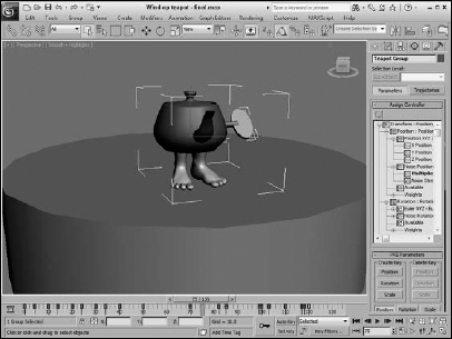
Figure 37.20 shows the teapot as it dances about, compliments of a controlled noise controller.
FIGURE 37.20 The wind-up teapot moves about the scene.
Filtering Tracks and Creating Track Sets
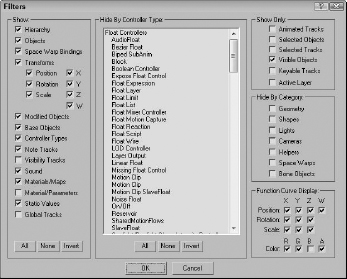
With all the information included in the Track View, finding the exact tracks you need can be difficult. The Filters button on the Key Tangents toolbar (or in the Display menu) can help. Clicking this button (or pressing the Q keyboard shortcut) opens the Filters dialog box, shown in Figure 37.21.
FIGURE 37.21 The Filters dialog box lets you focus on the specific tracks.
Using the Filters dialog box
Using this dialog box, you can limit the number of tracks that are displayed in the Track View. The Show section contains many display options. The Hide by Controller Type pane lists all the available controllers. Any controller types selected from this list do not show up in the Track View. You can also elect to not display objects by making selections from the check boxes in the Hide By Category section.
The Show Only group includes options for displaying only the Animated Tracks, Selected Objects, Selected Tracks, Visible Objects, Keyable Tracks, Active Layer, or any combination of these. For example, if you wanted to see the animation track for a selected object, select the Animated Tracks option and click OK; then open the Filters dialog box again, choose Selected Objects, and click OK.
You can also specify whether the function curve display includes the Position, Rotation, and Scale components for each axis or the RGB color components.
Creating a track set
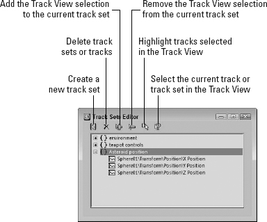
A selection of tracks can be saved into a track set by clicking the Edit Track Set button located at the bottom of the Track View interface. This button opens the Track Sets Editor, shown in Figure 37.22. Clicking the Create a New Track Set button in the Track Sets Editor creates a new track set containing all the currently selected tracks and lists it in the editor window. Selected tracks can be added, removed, and selected using the other editor buttons.
FIGURE 37.22 The Track Sets Editor dialog box lets you name track selections for easy recall.
After a track set is created, its tracks can be instantly selected by choosing the track set's name from the drop-down list located next to the Edit Track Set button at the bottom of the Track View window.
Working with Controllers
Controllers offer an alternative to positioning keys manually. Each controller can automatically control a key's position or a parameter's value. The Controller menu includes several commands for working with controllers. The Copy Controller and Paste Controller commands let you move existing controllers between different tracks, and the Assign Controller command lets you add a new controller to a track.
Cross-Reference
Chapter 22, “Animating with Constraints and Simple Controllers,” covers all the various controllers used to automate animated sequences.
Although the commands are named Copy Controller and Paste Controller, they can be used to copy different tracks. Tracks can be copied and pasted only if they are of the same type. You can copy only one track at a time, but that single controller can be pasted to multiple tracks. A pasted track can be a copy or an instance, and you have the option to replace all instances. For example, if you have several objects that move together, using the Replace All Instances option when modifying the track for one object modifies the tracks for all objects that share the same motion.
All instanced copies of a track change when any instance of that track is modified. To break the linking between instances, you can use the Controller ![]() Make Unique menu command.
Make Unique menu command.
Selecting the Controller ![]() Assign Controller menu command opens the Assign Controller dialog box, where you can select the controller to apply. If the controller types are similar, the keys are maintained, but a completely different controller replaces any existing keys in the track.
Assign Controller menu command opens the Assign Controller dialog box, where you can select the controller to apply. If the controller types are similar, the keys are maintained, but a completely different controller replaces any existing keys in the track.
Using visibility tracks
When an object track is selected, you can add a visibility track using the Tracks ![]() Visibility Track
Visibility Track ![]() Add menu command or the Object Properties dialog box. This track enables you to make the object visible or invisible. The selected track is automatically assigned the Bézier controller, but you can change it to an On/Off controller if you want that type of control. You can use function curves mode to edit the visibility track.
Add menu command or the Object Properties dialog box. This track enables you to make the object visible or invisible. The selected track is automatically assigned the Bézier controller, but you can change it to an On/Off controller if you want that type of control. You can use function curves mode to edit the visibility track.
Adding note tracks
You can add note tracks to any track and use them to attach information about the track. The Tracks ![]() Note Track
Note Track ![]() Add menu command is used to add a note track, which is marked with a yellow triangle and cannot be animated.
Add menu command is used to add a note track, which is marked with a yellow triangle and cannot be animated.
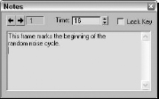
After you've added a note track in the Controller pane, use the Insert Keys button to position a note key in the Key pane by clicking in the note track. This adds a small note icon. Right-clicking the note icon opens the Notes dialog box, where you can enter the notes, as shown in Figure 37.23. Each note track can include several note keys.
The Notes dialog box includes arrow controls that you can use to move between the various notes. The field to the right of the arrows displays the current note key number. The Time value displays the frame where a selected note is located, and the Lock Key option locks the note to the frame so it can't be moved or scaled.
You can use the Tracks ![]() Note Track
Note Track ![]() Remove menu command to delete a selected note track.
Remove menu command to delete a selected note track.
FIGURE 37.23 The Notes dialog box lets you enter notes and position them next to keys.
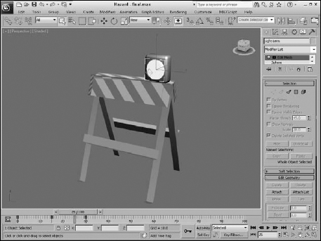
Tutorial: Animating a hazard light
As an example of working with the Track View, you'll animate a flashing hazard light in this tutorial.
To animate a flashing hazard light using function curves, follow these steps:
- Open the Hazard.max file from the Chap 37 directory on the CD.
This file contains a hazard barrier with a light.
- Select Omni01, open the Track View–Curve Editor, and locate the Omni light's Multiplier track. (You can find this track under the Objects Omni01 Object(Omni Light) Multiplier menu command.) Click the Insert Keys button (or press the A key), and create a key on the dotted line (its current multiplier value) at frame 0 and at frame 15. Set the end key to a value of 1.2.
- Select the first key and set its position to 0 by moving the key down or by typing 0 in the value display field. Click the Zoom Value Extends button to better see the shape of the curve. Click the Play button.
The light comes on slowly. It should be either on or off, so you need to change the tangent types to Stepped.
- Select both keys, and click the Set Tangents to Stepped button. Click the Play button.
The light turns on at frame 15.
- Select the first key, and choose the Move Keys Horizontal button from the Move Keys flyout. Hold down the Shift key and drag right to copy the key at frame 30.
The light now turns off at frame 30. You can continue to make the rest of the keys in that fashion, but using the Parameter Out of Range feature to complete the animation is easier.
- With the Multiplier curve selected, click the Parameter Curves Out-of-Range Types button or Choose Out-of-Range Types from the Controller menu item. The Out-of-Range Types dialog box appears. Choose Cycle, and click OK.
Figure 37.24 shows the Stepped tangents.
- Click Play.
The light flashes off and on. The animation would be more convincing if the light lens object appeared to turn off and on as well. Next, you animate the self-illumination of the lens material.
FIGURE 37.24 The curve with Stepped in and out tangents and a Cycle Parameter Out-of-Range type
- With the Omni light's multiplier track still selected, right-click over the track in the controller pane and choose Copy. Locate and select the Light Lens material's Self-Illumination track. (You can find this track under the Scene Materials Lens (Standard) Shader Basic Parameters Self-Illumination menu command.) Right-click, choose Paste, and paste as Copy.
- Because the Self-Illumination should top out at 100 percent, not 120 percent, select the second key and change its value to 100. Click the Play button.
The Omni light and lens flash off and on together.
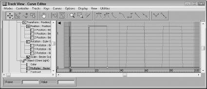
Figure 37.25 shows the hazard light as it repeatedly blinks on and off.
FIGURE 37.25 The hazard light flashing on
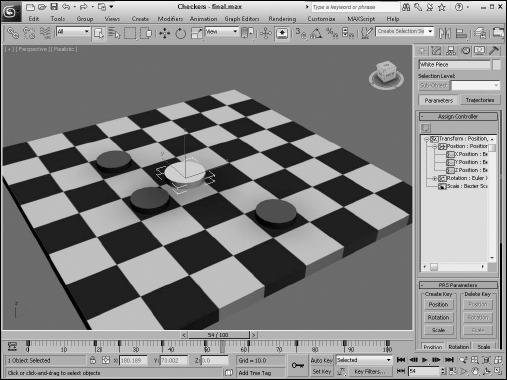
Tutorial: Animating a checkers move
As an example of working with function curves, you'll animate a checkers move in this tutorial. It is often easiest to block in the animation using keyframing and then to refine the animation in the Track View.
To animate a white checker making its moves, follow these steps:
- Open the Checkers.max file from the Chap 37 directory on the CD.
This file contains a simple checkerboard with one white piece and three red pieces.
The white checker is on the wrong-colored square to start, so first you move it into place and then to each successive position.
- Turn on Auto Key. Move the time slider to frame 25, and move the white checker to the square with the “1” text object (visible in the Top viewport). Move the time slider to 50, and move the white piece to the “2” position. At frame 75, move it to the “3” position, and at 100, move it to the “4” position. Turn off Auto Key.
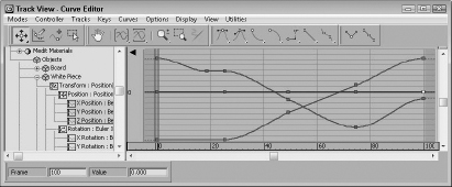
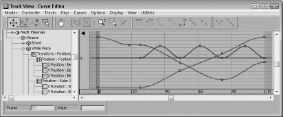
- Right-click over the white piece, and choose Curve Editor to open the Track View–Curve Editor. The white piece's X, Y, and Z Position tracks should be highlighted, and you should be able to see the function curves in the graph editor. If not, find them by choosing Objects White Piece Transform Position X, Y and Z Position.
Keeping in mind that RGB (red, green, blue) = XYZ, you can see the white checker's movement across the board. From 0 to 25, it moves only in the X direction. From 25 to 100, it moves diagonally across the board as indicated by the slope of both the X and Y curves. Note that when the object goes back the other way in the X direction at frame 75, the curve goes in the opposite direction, as shown in Figure 37.26.
FIGURE 37.26 The blocked-in animation curves for the white piece
- Click the Play button.
The white piece slides sloppily around the board. Next, you create keys to make it hop over the red pieces.
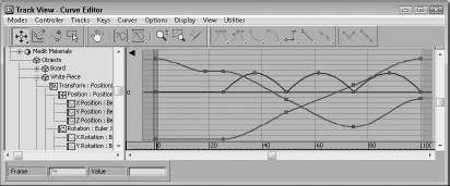
- Click the Insert Keys button, or select Insert Keys from the right-click menu. Click to insert keys on the Z-position track between the second, third, fourth, and fifth keys.
- Select Move Keys Vertical from the Move Keys flyout, and select the three new keys. Move them up about 50 units, as shown in Figure 37.27.
FIGURE 37.27 The new keys are moved up.
The white piece hops over the red pieces, but the motion is not correct. The In and Out tangents should be fast so the piece does not spend much time on the board.
- With the new keys still selected, hold the Shift key down, and move the handles on the keys to make them discontinuous tangent types, as shown in Figure 37.28.
FIGURE 37.28 The In and Out tangents corrected for the new keys
The hopping looks better, but the sliding motion would look better with a slight pause before hopping over the first red piece.
- Select Move Keys Horizontal from the Move Keys flyout, and choose the second X-position track key. Hold down the Shift key, and move the key a few frames to the left to make a copy of the original key. Click the play button.
The red pieces should disappear as the white piece hops over them.
- Scroll down the Controller pane on the left, and select the three red pieces. Under Tracks on the menu bar, choose Visibility Add.
A visibility track has been added to each of the red pieces, directly below the root name.
With visibility, a value of 0 is invisible, and a value of 1 is visible. You could change the tangent types to Stepped to turn the red pieces invisible from one frame to the next, but changing the entire track to an On/Off controller helps to visualize what is happening.
- Select the visibility track for Red Piece 01. Right-click, and choose Assign Controller. Choose On/Off.
Nothing seems to have happened. The Off/On controller is best used in Dope Sheet mode.
- Choose Dope Sheet from the Modes menu. The On/Off controller track is represented with a blue bar. Blue indicates “on” or visible. Click the Insert Keys button, and click to add a key at frame 50. The blue bar stops at the key at frame 50. Click Play.
The first red piece disappears at frame 50. You can copy and paste tracks to save yourself a bit of work.
- Select Red Piece 01's visibility track in the Controller pane. Right-click, and choose Copy. Select the visibility tracks for Red Piece 02 and Red Piece 03 (hold down the Ctrl key to add to the selection). Right-click, and choose Paste.
Paste as a Copy because the other pieces should disappear at different times.
- Move Red Piece 02's key to 75 and Red Piece 03's key to 100. Click Play.
Things are looking pretty good, but the animation would look better if the whole thing were faster.
- Click the Edit Ranges button and the Modify Subtree button. A World track bar appears at the top of the Key Pane. Click and drag the rightmost end of the range bar to frame 75 to scale all the tracks at one time. Click Play.
The animation is quite respectable as the white piece slides into the correct square and then hops over and captures the three red pieces.
Figure 37.29 shows the checkerboard.
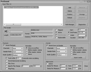
Using the ProSound dialog box, you can load and arrange multiple sound files. ProSound supports loading in WAV and AVI sound files. For the selected sound file, you can view its Length, Format, and Statistics. You also can set the sound's Start and End frame. Multiple other options are available for controlling how the audio file plays and how it interacts with other sounds.
The ProSound dialog box also includes some Metronome settings for keeping a defined beat. For a metronome, you can specify the beats per minute and the beats per measure. The first option sets how often the beats occur, and the second option determines how often a different tone is played. This dialog box also contains an Active option for turning the metronome on and off.
FIGURE 37.29 The checker pieces on the checkerboard
Using the ProSound Plug-in
Max includes an audio plug-in called ProSound for adding multiple audio tracks to a scene. You need to initialize the plug-in before you start, using the Animation panel in the Preference Settings dialog box. You can access this dialog box with the Customize ![]() Preferences menu.
Preferences menu.
To select the ProSound plug-in, click the Assign button and select the ProSound option. Once enabled, you can access ProSound by right-clicking the Sound track in the Track View and choosing the Properties menu. This opens the ProSound dialog box, as shown in Figure 37.30.
FIGURE 37.30 The ProSound dialog box lets you configure sounds to play during the animation.
Tutorial: Adding sound to an animation
As an example of adding sound to an animation, you'll work with a hyper pogo stick and synchronize its animation to a sound clip.
To synchronize an animation to a sound clip, follow these steps:
- Open the Hyper pogo stick with sound.max file from the Chap 37 directory on the CD.
- In the Track View–Dope Sheet window, right-click the Sound track and select Properties from the pop-up menu to open the ProSound dialog box. In this dialog box, click the Add button. Then locate the boing.wav file from the Chap 37 directory on the CD, and click OK. Make sure the Permit Playback option is selected.
The sound file appears as a waveform in the Track View, as shown in Figure 37.31.
FIGURE 37.31 Sounds loaded into the sound track appear as waveforms.
Note
The ProSound dialog box includes a play button that lets you play the sound before loading it.
- Enter a Start frame value of 2 for the audio file to align with the pogo stick's upward motion.
- Click the Play Animation button, and the sound file plays with the animation.
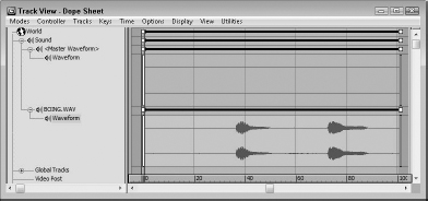
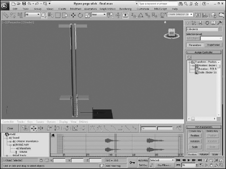
Figure 37.32 shows the sound track under the Track Bar for this example.
FIGURE 37.32 To help synchronize sound, the audio track can be made visible under the Track Bar.
Summary
Using the Track View, you have access to all the keys, parameters, and objects in a scene in one convenient location. Different features are available in the different layouts. In this chapter, you accomplished the following:
- Learned the Track View interface elements
- Learned about the different Track View layouts, including the Curve Editor, Dope Sheet, and Track Bar
- Discovered how to work with keys, times, and ranges
- Controlled and adjusted function curves
- Selected specific tracks using the Filter dialog box
- Assigned controllers
- Explored the different out-of-range types
- Added notes to a track
- Added multi-track audio with ProSound
The next chapter dives into working with characters, rigging, and bones.