
9.1 General Considerations
You may have noticed that the top skirt shown in Figure 7-5 and included in Listing 7-2 used an exaggerated spacing between the skirt and the tower. This was necessary because a thick-wire tower model was used and to comply with the requirement that the spacing be at least several radii, it was necessary to exaggerate the spacing. However, to overcome such inconvenience and to make the tower model more realistic, the usual practice when modeling top hats, skirts, and so on is to use the lattice tower model, where the wires are all rather thin and thus can accommodate a closer spacing of conductors.
Another consideration to keep in mind when modeling closely spaced conductors is to keep the adjacent segments aligned as closely as possible. For instance, a top-skirt wire extending down five segments on the tower should itself contain five segments, and those segments should be aligned as closely as practical with the segments on the tower.
Also, when you want to examine the current distribution on a lattice tower, you must remember that the total current distribution on a lattice tower model is the vector sum of the current distributions on each tower leg. Therefore all legs of a tower must be included to determine the total current distribution. It is also important to recognize that the current in the horizontal girth wires should not be included in the current distribution.
Fortunately, it is not difficult to write a postprocessing computer program to read the NEC-2 output file and to determine the current distribution on a lattice tower according to these requirements.
9.2 Top Loading
Adding a “top hat” to a tower modifies the current distribution on the tower by terminating the top of the tower in a capacity, as opposed to leaving the top of the tower open. This causes the current at the top of the tower to increase from a near 0 value to a value determined by the amount of terminating capacity. When this is done, the current distribution along the entire height of the tower is changed, thus providing the means to achieve a more desirable drive point impedance or to modify the vertical angle of radiation.
From a mathematics viewpoint, the ideal top hat would be a horizontal disc because the capacity of a disc can be easily calculated. Unfortunately, the mechanical problems associated with implementing such a disc in the MF band make compromise necessary. The usual practice is to use a section of the upper set of guy wires as a downsloping top hat. This does pose a limitation on how much top loading can be used, however. The current flowing in the guy wire top hat is made up of both a horizontal component and a downward vertical component. The horizontal component makes no contribution to the desired vertically polarized radiated field and the downward vertical component of current causes some measure of tower shielding. About 30° is generally taken as the practical limit for extending a foreshortened broadcast tower.
9.2.1 Estimating the Size of the Top Hat
In theory, the size of the top hat can be estimated by considering the tower to be an open transmission line, and calculating the effective capacity of the missing phantom section. But unfortunately, if that capacity is to be created using sections of the upper guy wires, there is no convenient way to determine how long the guy wire should be to create that capacity. Therefore, a starting point would be to make the guy wire section the length needed to make the overall length of tower plus guy wire equal to the desired tower height. A NEC-2 run can then determine the effect of that length and adjustments can be made as necessary.
9.2.2 Determining the Degree of Top Loading
The effect of the top load can be estimated by recognizing that the current maximum occurs at a fixed distance from the top of an unloaded tower. This is generally taken to be 90° but the finiteness of the physical tower modifies this somewhat.
Refer to Figure 9-1, in which the lower curve shows the current distribution on a 90° tower. Here the maximum current occurs at 9° which is 81° below the top of the tower, as opposed to the generally assumed 90°.
Continuing now with the example in which we seek to load a 60° tower to an effective height of 90°, we start by generating a NEC-2 input file that models the 60° tower complete with the guy wire sections as its top hat. Such NEC-2 input file code is shown as TL.NEC in Listing 9-1.
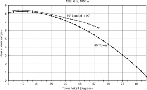
FIGURE 9-1![]()
Current distribution, 60° tower loaded to 90°.
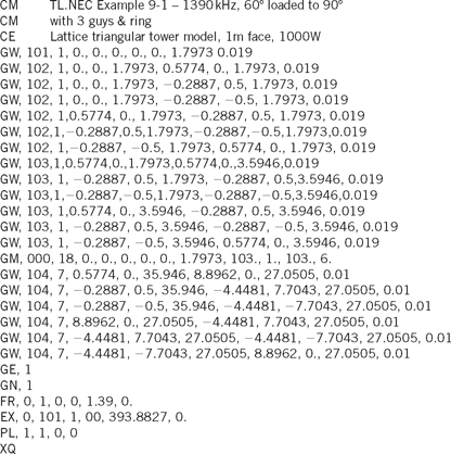
A lattice tower model is used with wire tag 101 being the singlefeed wire of the lattice tower configuration shown in Figure 3-1(e). Wire tag 102 makes up six segments of the spider and girth ring. Wire tag 103 is the standard section composed of three legs and a three-wire top girth. The GM command stacks eighteen standard sections to reach the tower height of 35.946 meters. Wire tag 104 creates the top load with the guys extending from the top of the tower down and outward to the 27.0505-meter level. The last three segments labeled tag 104 create the ring at the bottom of the top load wires.
Figure 9-2 shows the NVCOMP.EXE display of the modeled tower.
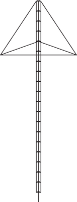
FIGURE 9-2![]()
NVCOMP.EXE view of top-loaded tower.
The output file generated by this code reveals the current distribution for the top-loaded tower. This is shown by the top curve of Figure 9-1. At the lower levels, the current distribution is seen to be much like that of the full-sized 90° tower. The current magnitude peaks at 9° on the top-loaded 60° tower just as it does on the 90° tower, suggesting that there is an effective height of 81° above the 9° height. But in reality the top-loaded 60° tower has only 51 physical degrees above the current maximum. Thus, the top-hat loading is adding 81° − 51° = 30° of phantom tower height to the 60° tower.
It is interesting to notice here that the current distribution on the 60° tower begins to deviate from that of the 90° tower as the top of the 60° tower is approached. This is caused by the interaction of the currents on the down-sloping top-load wires and the currents on the physical tower.
9.3 Skirted Towers
In addition to using a tower skirt to electrically shorten a tower for the purpose of detuning, the skirt is sometimes used to alter the current distribution on the tower and thus modify the vertical radiation pattern. Consider the case where it is desired to use a single tower for AM operation at 1430 kHz and also to support an FM antenna. The FM application requires a 500-foot tower but such a tall tower at 1430 kHz produces an undesirable radiation pattern with much of the radiation going into a high-angle lobe. See Figure 9-3.
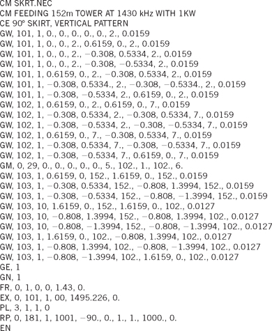
To mitigate this problem, a 90° skirt can be placed at the top of the 500-foot tower to electrically shorten the tower to an effective 318 feet. The input file to perform this modifi cation is shown as SKRT.NEC in Listing 9-2.
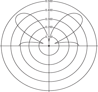
FIGURE 9-3![]()
Vertical radiation pattern of 500-foot tower at 1430 kHz.
As usual for this type application, the lattice tower model is used. Wire tag 101 generates the feed wire; it also creates the spider and girth to connect the feed wire to the three legs of the tower. Wire tag 102 is a 5-meter standard section and the GM command stacks twenty-nine of these standard sections to achieve the desired height.
Wire tag 103 generates the skirt with the first three commands creating the horizontal support arms, each standing off 1 meter from the tower leg. The next three commands with tag 103 are the vertical skirt wires running from the horizontal support arms at the top of the tower down to the lower support arms located at the 102-meter level AGL.
Notice here that the vertical skirt wires are 50 meters in length so they have been assigned ten segments each to match the length and alignment of the segments on the tower. The last three commands with tag 103 make up a ring at the bottom end of the skirt.
This input code also includes the PL command to generate a separate output file for plotting the vertical radiation pattern as generated by the RP command. The PL file as saved must be altered to accommodate the particular plotting arrangement that will be used.
See Appendix A for more detail on both the RP and PL commands. Figure 9-4 shows an NVCOMP.EXE view of the upper portion of the tower that contains the skirt wires.
FIGURE 9-4![]()
NVCOMP.EXE view of 500-foot tower with 90° top skirt.
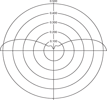
FIGURE 9-5![]()
Vertical radiation pattern of 500-foot tower using 90° top skirt at 1430 kHz.
Figure 9-5 is a plot of the vertical radiation pattern as generated by the skirted tower. It is interesting to compare this figure with Figure 9-3 to appreciate the effect of the skirt.
9.4 Folded Monopole
Using skirts to create a folded monopole antenna permits a grounded tower to be used as an AM broadcast antenna. Also, using a grounded tower as a folded monopole eliminates the need for isocouplers or other devices to bring transmission lines and lighting wires across a base insulator. In addition, a folded monopole is an effective way to raise the radiation resistance of a short tower. The latter is illustrated in the following example.
Consider the case of a 170-foot (51.816 meters) triangular tower with a 12-inch face operating at 1000 watts on 1070 kHz. The tower is only 66° at the operating frequency and if used as such, NEC-2 will calculate a drive point impedance of only 14 – j79. If, however, the short tower is converted to a folded monopole by adding a full-length skirt and a single-drive wire from the bottom of the skirt to ground, then NEC-2 calculates the drive point impedance to be 97 – j249. The NEC-2 input file shown as FLMO.NEC in Listing 9-3 generates the data on this folded monopole.
Wire tag 101 is the feed wire connecting the skirt's bottom ring to ground. Wire tag 102 is the grounded standard section starting at ground level and running up 10 feet (3.048 meters). The first three commands describe the three tower legs and the next three commands describe the top girth on the standard section. Following that, the GM command stacks sixteen standard sections to reach the height of 51.816 meters. Finally, wire tag 103 creates the full-length skirt using three 1-meter supporting arms at the top of the tower, three skirt wires, and three wires making up the ring at the bottom of the skirt. The skirt wires each have sixteen segments to match those on the tower.
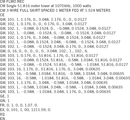
FIGURE 9-6![]()
NVCOMP.EXE view of lower portion of folded monopole.
Figure 9-6 shows the NVCOMP.EXE display of the lower portion of the skirted tower, including the feed wire.
The 97-ohm resistive component of the monopole can be transformed to near 50 ohms by placing a shorting spider at a selected height on the skirt. Because NEC-2 can accept connections only at the end of a segment, the shorting height used in the analysis is limited to the heights of the segment ends. Choosing a height of 5 segments up the skirt places a short at 18.288 meters and the resulting drive point impedance becomes 44 + j200. This calculated value is a starting place for the physical adjusting process. In practice, the shorting spider would be located a bit higher than this to get a drive point resistance closer to 50 Ω. Add the following three commands to Listing 9-3 to place this short at 18.288 meters.
9.5 Exercises
9-1. Explain how the current moment of a skirted tower is calculated.
9-2. Explain how the current moment of a top-loaded tower is calculated.