
3.1 Modeling Guidelines
Towers are modeled with short, straight wire segments. The antenna towers and any other conducting objects in the vicinity that affect its performance must be included in the model. Although one might be inclined to duplicate the physical detail of the antenna as closely as possible, it must be kept in mind that NEC-2 has significant limitations concerning radius changes, segment lengths, spacing, and so on that sometimes make an exact physical duplication yield inaccurate NEC-2 responses. Therefore, the suggestion offered here is that you use the simplest model that conforms to the rules and produces a reasonably close approximation to measured data. Although a model configuration is recommended here, guidelines and experience gained by using the code will aid the user in developing a satisfactory model to suit individual need.
In the sections that follow, a number of requirements are suggested concerning the layout and physical size of the radiator's conductors and segments. However, it is important to realize that, for the most part, these suggestions are general and do not constitute exact, fixed requirements that cannot be varied. The requirements are indeed meaningful and should be kept in mind and followed as guidelines when it is practical to do so. On the other hand, considerable latitude exists in modeling radiators for broadcast applications.
When modeling the radiator, the main electrical consideration is segment length, Δ, relative to the wavelength, λ. The size of the segments determines the resolution in solving for the current on the model since the current is computed at the center of each segment. Generally, Δ should be less than about 0.05 λ at the desired frequency although somewhat longer segments may be acceptable on long wires with no abrupt changes, such as a tower radiator. However, extremely short segments, less than about 10−3 λ, should be avoided to prevent numerical inaccuracy.
The wire radius, a, relative to λ is limited by the approximations used in the NEC-2 code. The acceptability of these approximations depends on the value of a/λ, which should be chosen such that 2πa/λ is much less than 1.
The accuracy of the numerical solution also depends on Δ/a Studies of the computed field on a segment due to its own current have shown that Δ/a must be greater than about 8 for errors of less than 1 percent. When the EK command is used, Δ/a may be as small as 2 for the same accuracy.
Segments with small Δ/a should be avoided at bends. If at a bend, the center of one segment falls within the radius of the other segment, severe error will occur.
Segments must not intersect other than at their ends, and segments that are electrically connected must have coincident end points. However, segments will be treated as connected if the separation of their ends is less than about 10−3 times the length of the shorter segment. When possible, however, identical coordinates should be used for connected segment ends.
Failure to observe this requirement may appear when modeling ground screens. Since NEC-2 cannot model wires underground, the ground screen must be modeled as being slightly above ground. If it is modeled too close to the ground, this requirement will be violated. NEC-2 will usually show an error and tell you if this occurs, however.
The angle of the intersection of wire segments in NEC-2 is not particularly restricted, although the acute angle should not be so small as to place the observation point on one wire segment within the volume of another wire segment. Thus, as a minimum, one must ensure that the angle is large enough to prevent overlaps.
3.2 Guideline Summary
Generally speaking, specifying 20 segments on a broadcast tower will produce segment lengths that satisfy the modeling requirements. When specifying connecting wires, however, shorter segments can be used since the connecting wires usually have a smaller radius.
3.2.1 Modeling the Radiator
In general, the following guidelines should be followed in modeling the radiator proper.
- Segment length, Δ, should be less than about 0.05 λ and longer than 10 −3 λ at the desired frequency.
- Extremely short segments (less than about 10 −3 λ) should be avoided.
- The wire radius, a, should be such that λ/a is greater than 30 and 2π(a/λ) is much less than 1.
- The ratio Δ/a must be greater than about 8. When the EK command is used, Δ/a may be as small as 2.
- Segments with small Δ/a should be avoided at bends.
- The angle of the intersection of wire segments should not be so small as to place the center point on one wire segment within the volume of another wire segment.
- Segments may not overlap.
- Radius changes between connected segments decrease accuracy, particularly with small Δ/a.
- The ratio of larger segment length to smaller segment length should not exceed 5.
- When wires are parallel and close together, the segments should be aligned.
- Wires should be separated by a distance of several radii.
3.2.2 Modeling the Voltage Source
The applied-field voltage source (I1 = 0 on the EX command) is the most appropriate for broadcast work.
When defining a voltage source, keep the following points in mind:
■ A segment is required at each point where a network connection or voltage source will be located because networks and voltage sources appear in the center of a segment.
■ The segments on each side of a voltage source segment should be parallel and have nearly the same length and radius as the voltage source segment.
■ If the source is on a segment connected to a ground plane, the segment should be vertical.
■ When multiple wires are connected to the ends of the voltage source segment, the length of each segment at the junction should be made equal to that of the source segment.
3.3 Tower Configurations
Generally speaking, tower models fall into two categories: thick-wire models and lattice models. Thick wires are simply a single conductor with a rather large radius of 0.5 meter or so. Lattice models represent the tower using a leg and crossbar structure very much like the construction of the actual tower. A triangular tower might be modeled with three legs interconnected with multiple horizontal ring girths at intermediate heights. In Figure 3-1, parts (a), (b), and (c) represent thick-wire models and parts (d) and (e) represent lattice models.
It appears that every NEC-2 user has an idea of the best tower model configuration. It is important, however, to recognize that the limitations of NEC-2 sometimes prevent a direct physical replication from yielding accurate self-impedance data on a single tower. When used in an array, however, the final result is determined more by the effects of mutual coupling between towers than it is by the features of the individual towers. This reduces the importance of which tower model configuration has been used and leads one to use the simplest configuration.
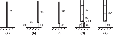
FIGURE 3-1![]()
Tower configurations.
The sections that follow describe some common configurations of tower models.
3.3.1 Single-Wire Configuration
The most simple of all tower configurations is a single wire with a radius equal to the equivalent radius of the tower. See Figure 3-1(a). This configurations finds many applications, especially where detail is not required, for example, in evaluating the parasitic effect of a distant unused tower.
There is no rigorous method to determine the equivalent radius of a noncircular tower. Several methods have been mentioned such as the radius of the inscribed or circumscribed circle, the radius that yields an equivalent inductance, and so on. This book follows the lead given in Morecroft's Principles of Radio Communication and defines the equivalent radius of a noncircular tower as the radius of a circle whose circumference equals the perimeter of the noncircular tower. For a three-leg tower with a face equal to F, the equivalent radius, a, is taken to be
(1)
The radius is sometimes adjusted to other values in the attempt to match calculated and measured impedances, however.
3.3.2 Four-Wire Configuration
The most obvious model for a tower is shown in Figure 3-1(b). Here the wire labeled 1 represents the tuning network cabinet and its connection to ground. The wire labeled 2 is the connecting lead from the network cabinet to the tower base and might contain the inductance of the single-turn lightning-arrestor choke. Wire 3 has been assigned to the tower base insulator including the tower base pedestal. A series capacitor is usually placed in this wire to represent the base insulator capacity. If no insulator capacity is to be included, this wire must be omitted to prevent shorting the base to ground. Finally, the radiating tower proper is assigned wire 4.
Unfortunately, the error generated by the approximations used in NEC-2 often causes unsatisfactory results when using this configuration. The failure to accurately handle junctions of wires with differing radii and adjacent wire segments of unequal length, and the difficulty in modeling small loops, are some of the NEC-2 shortcomings that often cause unsatisfactory results using this configuration.
3.3.3 Two-Wire Configuration
The two-wire configuration shown in Figure 3-1(c) is a modified representation of the four-wire configuration. Wires 1, 2, and 3 of Figure 3-1(b) have been combined into a single vertical feed wire in Figure 3-1(c). The length and equivalent radius of this wire can be used as an adjustment parameter to match calculated and measured impedance. The logic here is that the equivalent radius of the ground connections to the tuning network cabinet as well as that of the base insulator and pedestal are unknown and probably large, so some license can be taken in setting a value for them. This is the model preferred by this writer when using the thick-wire category.
3.3.4 Lattice Configuration
The lattice configuration appears to be useful for instances that prefer all wires to be of the same or nearly the same radius. Some examples of this are antennas employing skirts, folded monopoles, and top-loaded antennas.
The lattice configuration can be generated with reasonable ease by using the move command, GM, in NEC-2 to stack identical sections vertically. Please read the description of the GM card in Appendix A. The configuration shown in Figure 3-1(d) will be used to illustrate a method of writing such an input file.
Coding the Lattice Configuration
Assuming a triangular tower with 24-inch face and 90° height at the frequency of 1500 kHz, the tower height, G, is 49.9675 meters. The tower legs radius, a, is 0.0191 meters.
A good starting place in coding the tower is the feed wire, which is also the wire carrying the base insulator. In this case, the insulator, including flanges, is arbitrarily assigned 1 meter in height with the bottom being 1 meter above ground. This assembly includes the spider connections necessary to connect the feed wire to the tower legs and a ring girth around that spider.
We must know the coordinates of each corner of the tower in order to define the spider and ring girth. The coordinates of the corners can be calculated as follows.
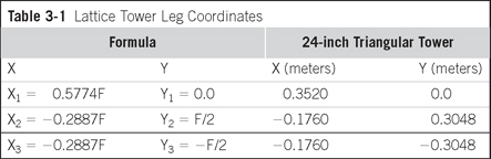
The triangular tower in this example has a 24-inch face (F = 24″). If we set the tower such that it is centered on the origin with one corner pointing north, the X-Y coordinates of the north corner are calculated by recognizing that the north corner of the tower is located on the +X axis at a distance equal to the radius of a circumscribed circle about the tower or
The Y coordinate, Y1, of this corner is, of course, zero.
The X coordinate of the lower right corner is the negative of the radius of a circle inscribed within the tower or
The Y coordinate, Y2, of this corner is simply F/2.
Finally, the X coordinate of the third corner, X3, is the same as that of the second corner so X3 = X2 and the Y coordinate of the third corner is the negative of that of the second corner so Y3 = − Y2.
The results are shown in Table 3-1. It is important to remember that although the tower face dimension is usually expressed in inches, NEC-2 requires that the corner coordinates be in meters.
Enough information exists now to start writing the commands to create the lattice tower. If the concrete base is defined to be 1 meter high, then the drive wire runs vertically from 1 meter to 2 meters. The
Table 3-1 Lattice Tower Leg Coordinates
GW command defining the drive wire (wire 1) to which we have assigned 1 segment and set the radius to be 0.0191 meter is
At the top of the drive wire is the spider assembly, which runs from the drive wire to each leg and is used to connect the drive wire the tower legs. Using one segment on each spider leg, the code for the spider is:
A ring girth surrounds the spider to tie the ends of the spider together. Again using one segment on each wire, its code is:
This completes the drive wire and its top portions.
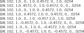
There is no defined routine to follow in coding a tower, so the tower wires can be defined in any order. In this case, the four grounding straps (defined collectively as wire 2) running down the concrete base pedestal will be considered next. The four grounding straps run horizontally from the bottom of the drive wire to the edge of the concrete base pedestal, which in this example has been chosen to be 36 inches in diameter. From the pedestal edge, the straps then run downward to the ground system.
The equivalent radius of a flat strap is commonly taken to be one-fourth the strap width. Assuming a 4-inch strap, this would be (0.25 × 4) inches × 0.0254 meters/inch = 0.0254 meters as the equivalent radius of the ground straps.
The four straps with two wires each and one segment on each wire are coded using eight lines, as follows:
The main radiator is considered next. It stacks on top of the drive wire spider, whose height is 2.0 meters (Z = 2.0 meters). The total height of the tower (defined collectively as wire 4) is required to be 499675 meters, so 47.9675 meters must be added above the spider. If we arbitrarily elect to divide the tower into segments that are 10 feet long (Δ= 3048 meters), then there will be 47.9675/3.048 = 15.7374 segments on the tower. One of those segments will be allocated as the standard to govern the stacking process, leaving a remainder of 14.7374 segments to be stacked. Since only an integer number of segments (14) can be stacked, the remainder (0.7374 × 3.048 = 2.2475 meters) will be included as a height adjuster section (collectively called wire 3) taking the height to Z = 4.2475 meters.
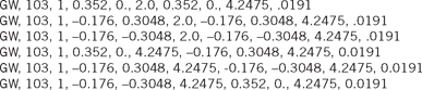
The code for the height adjuster section (which consists of three legs and a top ring girth) is:
Next comes the standard tower section (a component of wire 4), which is very similar to the height adjuster section. It differs only in that it is a full segment (Δ= 3.048 meters) in height. The bottom of the standard tower section is at Z = 4.2475 meters and the top is at Z = 7.2955 meters so the code for the standard tower section is:
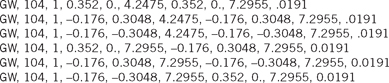
It is important to notice here that this standard section starts with the wire at tag 104, segment 1 and it includes five more wires, each with tag 104 and each with one segment. The entire section carries the tag 104 and there are a total of six segments in the standard section. Therefore, the standard section starts with wire tag 104, segment 1, and it ends with wire tag 104, segment 6. Please review the Segmentation Data in a NEC-2 output file with special attention being paid to the Segment Number and the associated Tag number to see how they relate.
Also, please read the description of the GM command in Appendix A before continuing.
Because the tower sections will only be stacked vertically, the GM card is written with no rotation and no movement in the X-Y directions. The standard section is repeated fourteen times with only an upward movement of 3.048 meters each time. Also note that the wire tag will not be incremented. Thus, the GM command is:
A bit of reassurance is in order at this time. We have just used 28 lines to describe one tower and these lines have required considerable effort to generate. It would then appear that an eight-tower array will require 224 hard-earned lines to describe the entire array. But such is not the case.
If all towers in the array are identical, then the GM command can be used to duplicate the entire tower with a single line. Thus, an eight-tower array will require only 7 more lines, all of which can be generated with relative ease.
As an example, we can duplicate the entire tower above (which is located at the origin) at a new location 50 meters north with this single command:
Proceeding along this GM command, the number 100 increments the existing tag numbers to put the tags in the 200 series on this tower 2. The numeral 1 indicates that one additional tower will be generated and the next three zeros show that the tower is not rotated in the move. The following three numbers are the coordinates of the new location; that is, X = 50 meters, Y = 0 meters, and Z = 0 meters. The next two numbers indicate the first segment in the move, tag 101, segment 1. The last two numbers indicate the last tag and segment of the tower and require a bit of explanation.
It is clear that tag 104 is indeed the last tag number. But tag 104 contains multiple segments so it is necessary to determine the number of the last segment of tag 104. This can be reasoned as follows. Tag 104 was first used on the starter section's six wires with one segment on each wire. Tag 104 was used again to vertically stack fourteen copies of the starter section, so it used 6 × 14 = 84 segments in the stacking process. Therefore, the last segment of tag 104 is 6 + 84 = 90.
Thus, the total tower structure starts at tag 101, segment 1, and ends at tag 104, segment 90.
Again, you are encouraged to review the GM command in the appendix to understand its coding better.
Simplified Lattice Model
The tower model shown in Figure 3-1(e) is essentially the same as that shown in Figure 3-1(d) with the tower base and insulator replaced by a single drive wire (refer to page 30). Notice that the single drive wire includes the spider and ring girth used to connect to the triangular tower. In one method of generating this tower configuration, the overall tower height is first defined. Then the center height of the insulator is taken as the center point of the drive wire. This defines the segment length as being twice the center height of the insulator. That same segment length is then used for the entire tower, so the number of segments is determined by dividing the tower height by the segment length.
for example, consider a 100-meter tower with the insulator center point located 2.5 meters above ground. The segment length will be 2 × 2.5 = 5 meters. The total number of segments is 100/5 = 20 segments. The drive wire uses one 5-meter segment, the standard section uses another, and then the GM command is used to stack eighteen more 5-meter segments to complete the total of twenty 5-meter segments making up the full tower height.
This model appears to work quite well and is the lattice model choice of this writer. When this configuration is used to model a 90° tower, the calculated self-impedance compares favorably with the published measured value, with the resistive component being reasonably close but with the reactive component being somewhat small.
3.4 Viewing Tower Configuration
The code for tower configurations as complex as the lattice are almost impossible to verify as error free without some computer help. Many of the commercial NEC-2 programs include a viewing capability that draws a 3-D view of the structure and thus reveals any errors in the coding. The public domain NEC-2 does not have that capability. Fortunately, however, there are several other public domain programs intended to work with NEC-2 to display the antenna geometry. Most, however, are tailored to work with the conventional NEC-2 coordinate system and incorrectly display files that use the broadcast coordinate system, which is described in Chapter 4.
Glenn Stumpff ([email protected]) has modified a viewing program called NV.EXE such that it accommodates both the use of the GM command and the modified coordinate system. Stumpff has called the modified program NVCOMP.EXE and has placed it on the Internet as a public domain program. At the time of this writing, the file nvnew.zip, which contains NVCOMP.EXE and other programs, can be downloaded from http://www.si-list.net/swindex.html or http://www.home.earth-link.net/~gstumpff/nvnew.zip.
A copy of NVCOMP.EXE is available on the CD that is included with this book.
NVCOMP.EXE reads the NEC-2 input file and draws a 3-D view of the antenna structure on the screen. If a multitower array is included in the NEC-2 file, all towers of the array are displayed in their proper positions. The display can be zoomed, moved, and rotated about all three axes and the image can be stored. On demand, NVCOMP.EXE can highlight each wire on the display, display the coordinates of each wire end, and show each wire radius. Instructions for using NVCOMP.EXE are given in Appendix C.
3.5 Exercises
3-1. Write the input file code to model a four-sided tower of the same configuration as shown in Figure 3-1(e). Make each face 48 inches and the total tower height 152.4 meters. Use a 10-foot standard section for stacking.
3-2. Verify the correctness of the model by viewing it using NVCOMP.EXE.
3-3. Use the GM command to add a second tower, identical to that in exercise 3-1, at a location 141.4214 meters northeast of the existing tower.
3-4. Verify the correctness of both towers by viewing the pair using NVCOMP.EXE.
3-5. Save the NVCOMP.EXE image of both towers as a .BMP file.