Managing VLANs
This section further discusses topics such as STP and VTP and how they affect your VLANs. For example, it wasn't too inspiring to lose your VLANs earlier, but it's better to have this happen in a lab than in a practical environment. Understanding VTP is critical to your success in supporting VLANs. Using the default of every switch being in the VTP server mode is chaotic to say the least. At most, only a few switches should be in the VTP server mode with many clients. Alternatively, configure them all as transparent mode. You previously learned how to control which VLANs are allowed on a trunk. Now you will optimize and control VLANs with pruning.
NOTE
An excellent tech note at Cisco.com is www.cisco.com/warp/public/473/103.html. It is titled “Best Practices for Catalyst 4000, 5000, and 6000 Series Switch Configuration and Management,” and that it is.
STP and VLANs
The Spanning Tree Protocol was a topic in Chapter 6. However, now that you have looked at VLANs, you must go back and revisit how STP works with VLANs in place. The initial release of IEEE 802.1Q only specified a single instance of STP. However, Cisco's PVST stands for Per VLAN STP, which means just what it says: small spanning trees. With PVST+, Cisco allows PVST and Mono Spanning Tree (MST) regions to interoperate. Between PVST and PVST+, the mapping of spanning trees is one-to-one. Between MST and PVST+, the MST spanning tree maps to one only PVST in the PVST+ region. The default mapping for the Common Spanning Tree (CST) is the PVST of VLAN1, which is the native VLAN. MST is actually IEEE 802.1s, which is a form of IEEE 802.1w (RSTP) that some Catalysts support via the set spantree mode mst and set spantree mst ? commands.
Helpful CatOS spanning tree commands include the following:
show spantree ?
show spantree mod#/port#
show spantree vlan# [active]
show spantree summary
show spantree blockedports
show spantree statistics
Review the IOS spanning-tree show commands with show spanning-tree ?. Example 7-24 reviews the shortcut commands for viewing STP on the CatOS. When you do not specify a VLAN, the native VLAN1 is assumed.
Example 7-24. Cisco's PVST
sw2900> show spant VLAN 1 Spanning tree enabled Spanning tree type ieee Designated Root 00-10-ff-e5-14-00 Designated Root Priority 32768 Designated Root Cost 0 Designated Root Port 1/0 Root Max Age 20 sec Hello Time 2 sec Forward Delay 15 sec Bridge ID MAC ADDR 00-10-ff-e5-14-00 Bridge ID Priority 32768 Bridge Max Age 20 sec Hello Time 2 sec Forward Delay 15 sec Port Vlan Port-State Cost Priority Fast-Start Group-Method --------- ---- ------------- ----- -------- ---------- ------------ 1/1 1 forwarding 19 32 disabled 2/2 1 not-connected 100 32 disabled 2/3 1 not-connected 100 32 disabled 2/4 1 not-connected 100 32 disabled 2/5 1 not-connected 100 32 disabled 2/6 1 not-connected 100 32 disabled 2/7 1 not-connected 100 32 disabled 2/8 1 not-connected 100 32 disabled 2/9 1 not-connected 100 32 disabled 2/10 1 not-connected 100 32 disabled 2/11 1 not-connected 100 32 disabled 2/12 1 not-connected 100 32 disabled sw2900> show spant 10 VLAN 10 Spanning tree enabled Spanning tree type ieee Designated Root 00-10-ff-e5-14-09 Designated Root Priority 32768 Designated Root Cost 0 Designated Root Port 1/0 Root Max Age 20 sec Hello Time 2 sec Forward Delay 15 sec Bridge ID MAC ADDR 00-10-ff-e5-14-09 Bridge ID Priority 32768 Bridge Max Age 20 sec Hello Time 2 sec Forward Delay 15 sec Port Vlan Port-State Cost Priority Fast-Start Group-Method --------- ---- ------------- ----- -------- ---------- ------------ 1/1 10 forwarding 19 32 disabled 1/2 10 forwarding 19 32 disabled 2/1 10 forwarding 100 32 disabled sw2900> show spant 20 VLAN 20 does not exist. |
Example 7-25 illustrates the shortcut commands for viewing STP on the IOS. Note again that VLAN1 is the default if not specified. Only a few ports are shown in the output, but remember that the interface is the actual interface on the box and the port number in parentheses is the way the interface was logically calculated for STP purposes.
Example 7-25. Cisco's PVST
sw3512xl#show span Spanning tree 1 is executing the IEEE compatible Spanning Tree protocol Bridge Identifier has priority 32768, address 00d0.7968.8480 Configured hello time 2, max age 20, forward delay 15 Current root has priority 32768, address 0010.ffe5.1400 Root port is 24, cost of root path is 19 Topology change flag not set, detected flag not set, changes 25 Times: hold 1, topology change 35, notification 2 hello 2, max age 20, forward delay 15 Timers: hello 0, topology change 0, notification 0 Interface Fa0/1 (port 13) in Spanning tree 1 is FORWARDING Port path cost 19, Port priority 128 Designated root has priority 32768, address 0010.ffe5.1400 Designated bridge has priority 32768, address 00d0.7968.8480 Designated port is 13, path cost 19 Timers: message age 0, forward delay 0, hold 0 BPDU: sent 26610, received 0 The port is in the portfast mode sw3512xl#show spanning-tree vlan 10 Spanning tree 10 is executing the IEEE compatible Spanning Tree protocol Bridge Identifier has priority 32768, address 00d0.7968.8481 Configured hello time 2, max age 20, forward delay 15 Current root has priority 32768, address 0010.ffe5.1409 Root port is 24, cost of root path is 19 Topology change flag not set, detected flag not set, changes 15 Times: hold 1, topology change 35, notification 2 hello 2, max age 20, forward delay 15 Timers: hello 0, topology change 0, notification 0 Interface Fa0/10 (port 23) in Spanning tree 10 is FORWARDING Port path cost 19, Port priority 128 Designated root has priority 32768, address 0010.ffe5.1409 Designated bridge has priority 32768, address 00d0.7968.8481 Designated port is 23, path cost 19 Timers: message age 0, forward delay 0, hold 0 BPDU: sent 186213, received 0 sw3512xl#show spanning-tree vlan 20 Spanning tree 20 is executing the IEEE compatible Spanning Tree protocol Bridge Identifier has priority 32768, address 00d0.7968.8482 Configured hello time 2, max age 20, forward delay 15 We are the root of the spanning tree Topology change flag not set, detected flag not set, changes 9 Times: hold 1, topology change 35, notification 2 hello 2, max age 20, forward delay 15 Timers: hello 0, topology change 0, notification 0 |
Show the spanning tree for each VLAN on each switch in your lab to get comfortable with STP and VLANs. Look back at Example 6-36 in the preceding chapter to review the STP port states in action, and be sure to review the best practices section. Feel free also to repeat any of the STP exercises from the preceding chapter with your current configuration.
It is a common practice to distribute your VLAN traffic across redundant trunk links, and there are many ways to accomplish that. Ideally you should plan your root bridges where you can using the CatOS set spantree priority pri# [vlan#] command or the IOS spanning-tree priority vlan# command and take advantage of Fast or Gigabit EtherChannel. Other STP tuning methods include STP path cost (set spantree portvlancost), which works with trunks from the same or a different switch and STP port priority (set spantree portvlanpri), which only works with both trunks on the same switch. Higher priority is given to lower values, such that a port priority of 20 would carry the VLANs over a particular trunk because it is less than the default of 128. To configure VLAN 100, 102, and 104 to use the fa0/1 trunk under the trunk interface, use the following command:
spanning-tree vlan 100 102 104 port-priority 20
Whereas the following command would allow the fa0/2 trunk to carry VLAN 101, 103, and 105:
spanning-tree vlan 101 103 105 port-priority 20
With the port cost method, the commands are as follows:
							spanning-tree vlan 100 102 104 cost 30
							spanning-tree vlan 101 103 105 cost 30
On one trunk, for example, you could set this command for all your even VLANs and on another trunk, you could set this for all your odd VLANs to help share the load between the trunks. This increases throughput capacity and offers fault tolerance for it; if one of the trunks fails, the other handles all the traffic.
Certainly, by now you are comfortable with CatOS and IOS differences, such as the fact that anything that starts with spanning-tree is IOS, whereas the CatOS equivalent is set spantree. If not, use the help (?) on both platforms and all the CatOS/IOS command tables in Part III of this book, “Supporting Ethernet, Switches, and VLANs,” to work your way through anything.
VLAN Trunking Protocol (VTP)
VTP is a Cisco proprietary Layer 2 multicast messaging protocol that can make VLAN administration easy or put you in a state of misery depending on how you look at it. You got a taste of that in the chapter scenario with both switches being in the server mode. VTP enables you to create a VLAN and have it propagate to other switches within the same domain. VTP transmits messages according to the VTP mode. From a practical sense, VTP is what saves you and me from going to each and every switch to create VLANs. See Table 7-4 for VTP operating modes.
NOTE
VTP has nothing to do with encapsulation or trunking; it is a communications protocol to distribute VLAN information across a common management domain. VTP messages are encapsulated inside of a trunking protocol frame such as ISL or 802.1Q.
| VTP Mode | Description | Storage |
|---|---|---|
| Server[*] | Just as it sounds, it sources and listens for VTP messages. Create, modify, and delete VLANs within a management domain. | NVRAM. |
| Transparent | Does not source or listen for VTP messages but does propagate those of neighbor switches. Create, modify, and delete VLANs, but they are locally significant to the switch. | NVRAM. |
| Client[*] | Processes and listens for VTP messages. Cannot create, modify, or delete VLANs. | Information is not stored in NVRAM. |
[*] When VTP clients or servers receive a message with the VTP multicast address of 01000ccccccc and a SNAP value of hex 2003, they process it according to revision numbers.
Assign a CatOS-based switch to a VTP domain using the following command: set vtp domain vtpname. (It is cAsE sEnSiTiVe). This can help divide a large network into smaller management domains. The command on an IOS-based switch is vtp domain vtpname in the VLAN database mode.
NOTE
If you change the domain name on one of the switches to something different and create VLAN30 on each switch, VLAN30 is VLAN30 regardless of the VTP name. This is true because the VTP domain name is not in the frame, only the number. Remember the type of frame here is Ethernet, and the protocols are IP and VTP.
Now you might be saying to yourself, “I have VLANs but I am not using VTP.” Well, I guess that is your decision to run around and create the same VLAN on every switch or do everything in the transparent mode because you worry about losing your VLANs. For small networks, that actually is a pretty good approach. On the other hand, the larger your network, the more rational you have to be with automating VLAN propagation by using VTP. This gets into a design issue, questioning how far VLANs should sprawl across the topology. Cisco now concurs that flatter is not necessarily better, so a given VLAN should not need to exist in very many switches. In this chapter, I hope you are experiencing the things that many people tend to experience first on live networks. Obviously, that is not the best time to learn VTP.
NOTE
Routers do not participate in VTP, so they ignore VTP messages and discard them at the router interface. Only trunk-enabled adjacent switches in the server or client mode actually pay attention to VTP messages.
VTP advantages are as follows:
VLAN consistency throughout a management domain
Less manual configuration for creating and deleting VLANs, but you still need to associate the ports at each device
More control and security through a VTP domain name and passwords
Limits the extent of VTP message propagation
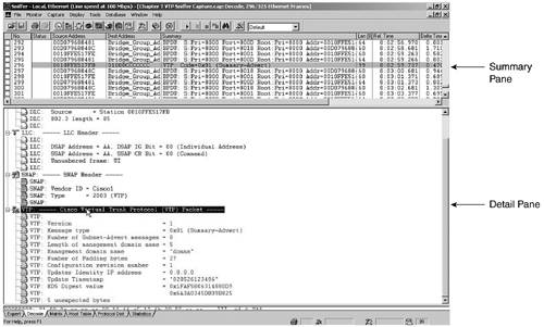
Take a few minutes and compare the VTP header in Figure 7-6 to Table 7-5.
| ISL | 802.3 | LLC AAAA03 | SNAP 00000C VTP 2003 | CRC |
|---|---|---|---|---|
| 26 bytes | 14 | 3 | 5 | 4 |
Sniffer clearly displays the Data Link Control (DLC), Logical Link Control (LLC), SNAP, and VTP headers. If you want to capture this on your own, remember to turn port monitoring on for the trunk and output the data to hosta, where the protocol analyzer is running. Make sure that VTP debug events are on and wait for the next VTP log message to appear on the console before you stop Sniffer as in Example 7-26. It is also helpful to make sure that you have the correct time and that logging and debug time stamps are turned on.
Example 7-26. Monitoring VTP Messages
sw3512XL(config)#service timestamps debug datetime localtime msec sw3512XL(config)#service timestamps log datetime localtime msec sw3512XL(config)#end sw3512XL#clear counters sw3512XL#clear log sw3512xl#debug sw-vlan vtp events vtp events debugging is on sw3512xl#configure terminal sw3512xl(config)#interface fastethernet 0/1 sw3512xl(config-if)#port monitor fastethernet 0/11 sw3512xl(config-if)#end sw3512xl#show port monitor Monitor Port Port Being Monitored --------------------- --------------------- FastEthernet0/1 FastEthernet0/11 sw3512xl#show log Syslog logging: enabled (0 messages dropped, 0 flushes, 0 overruns) Console logging: level debugging, 332 messages logged Monitor logging: level debugging, 0 messages logged Trap logging: level informational, 67 message lines logged File logging: disabled Buffer logging: level debugging, 332 messages logged Log Buffer (4096 bytes): ARENT MODE (nc = false) VTP LOG RUNTIME: Relaying packet received on trunk Fa0/11 - in TRANSPARENT MODE (nc = false) ... sw3512xl#show vlan brief VLAN Name Status Ports ---- -------------------------------- --------- ------------------------------- 1 default active Fa0/1, Fa0/3, Fa0/4, Fa0/5, Fa0/6, Fa0/7, Fa0/8, Fa0/9, Fa0/10, Gi0/1, Gi0/2 10 vlan10 active 20 vlan20 active Fa0/12, Fa0/12 1002 fddi-default active 1003 token-ring-default active 1004 fddinet-default active 1005 trnet-default active |
VTP messages always travel over the default VLAN. Figure 7-6 is an example of a VTP summary advertisement. Refer to Table 7-5 for VTP header information and Table 7-6 for VTP message types.
The Summary Pane and DLC header of Figure 7-6 show the destination MAC address of 01000CCCCCCC. LLC uses AA to indicate that the SNAP header follows. The SNAP header includes Cisco as a vendor/OUI with a type of 2003 for VTP. The VTP header includes such fields as the protocol version, a message type of 0x01 for the summary advertisement, the management domain size and name, any padding, the configuration revision number, the updater identity IP address, a time stamp, and an MD5 digest hash value.
| Message | Description |
|---|---|
| Summary advertisements | Issued by servers and clients every 5 minutes.
If higher revision number, the receiving switch issues an advertisement request for the new VLAN information. Fields include version, type, number of subnet advertisement messages, domain name length, managed domain name, configuration revision number, updater identity, update time stamp, and MD5 digest. |
| Subset advertisements | Issued due to changes such as creating, suspending, activating, renaming, or changing the MTU of a VLAN. One or more advertisements depending on how many VLANs. |
| Advertisement requests | When device hears of higher revision number, it asks for it. |
| VTP join messages | For pruning. |
The command show vtp statistics is used to track VTP activity, as you can verify in Example 7-27. You can compare the statistics to the VTP message types in Table 7-6 to see how many of each message type have been sent. Keep an eye on the “Number of config digest errors”; unless you have other transmit-type errors, it is a good indication that someone is trying to hack in and corrupt things.
Revision numbers are critical in the VTP server mode, but not used in the transparent mode. They range from 0 to 2,147,483,648. The set vtp domain name command is a quick way to reset the counter to 0 without having to make too many changes. Remember this when you are adding new switches into your environment.
The same version of VTP is needed throughout the management domain. VTP version 2 includes such functionality as Token Ring and various consistency checks. You can turn on version 2 with the set vtp v2 enable command and verify it with show vtp domain.
Example 7-27. VTP Statistics on IOS
sw3512xl>show vtp ? counters VTP statistics status VTP domain status VTP LOG RUNTIME: Relaying packet received on trunk Fa0/11 - in TRANSPARENT MODE (nc = false) sw3512xl>show vtp counters VTP statistics: Summary advertisements received : 8 Subset advertisements received : 1 Request advertisements received : 0 Summary advertisements transmitted : 1 Subset advertisements transmitted : 1 Request advertisements transmitted : 0 Number of config revision errors : 0 Number of config digest errors : 0 Number of V1 summary errors : 0 VTP pruning statistics: Trunk Join Transmitted Join Received Summary advts received from non-pruning-capable device ---------------- ---------------- ---------------- --------------------------- Fa0/11 1 0 0 sw3512xl>show vtp status VTP Version : 2 Configuration Revision : 0 Maximum VLANs supported locally : 254 Number of existing VLANs : 7 VTP Operating Mode : Transparent VTP Domain Name : donna VTP Pruning Mode : Disabled VTP V2 Mode : Disabled VTP Traps Generation : Disabled MD5 digest : 0x5F 0xFF 0xAC 0x3D 0xF9 0x1B 0x60 0x4B Configuration last modified by 192.168.5.18 at 12-5-02 03:25:47 |
Example 7-27 displays the IOS VTP commands, and Example 7-28 illustrates the same for CatOS.
Example 7-28. VTP Statistics on CatOS
sw2900> show vtp ? Show vtp commands: ----------------------------------------------------------------------------- show vtp domain Show VTP domain information show vtp help Show this message show vtp statistics Show VTP statistics sw2900> show vtp domain Domain Name Domain Index VTP Version Local Mode Password -------------------------------- ------------ ----------- ----------- ---------- donna 1 2 server - Vlan-count Max-vlan-storage Config Revision Notifications ---------- ---------------- --------------- ------------- 6 1023 1 disabled Last Updater V2 Mode Pruning PruneEligible on Vlans --------------- -------- -------- ------------------------- 0.0.0.0 disabled disabled 2-1000 sw2900> show vtp statistics VTP statistics: summary advts received 0 subset advts received 0 request advts received 0 summary advts transmitted 255 subset advts transmitted 1 request advts transmitted 0 No of config revision errors 0 No of config digest errors 0 VTP pruning statistics: Trunk Join Transmitted Join Received Summary advts received from non-pruning-capable device -------- ---------------- ------------- --------------------------- 1/1 0 0 0 |
The Example 7-28 output ends with displaying that the 2900 in the lab is a non-pruning-capable device. Just like you need to prune your plants as they grow, you should prune your VLANs, too.
VTP Pruning
Bridges and switches are inherently designed to flood multicast or broadcast frames as well as frames that they don't know what to do with. With VLANs, however, you can minimize this flooding in more ways than one. For example, back in the “Trunking” section, you restricted VLANs from crossing a trunk with the CatOS clear trunk vlan# command and the switchport trunk allowed or remove command on IOS switches.
You can also configure VTP pruning so that unless a frame needs to cross a trunk to get to a switch belonging to the same VLAN, it doesn't. This is kind of like throwing a bridge into VTP. Use the following CatOS commands for pruning:
set vtp pruning enable
clear vtp pruneeligible vlanrange
set vtp pruneeligible vlanrange
sh vtp domain (to check pruning results)
NOTE
The default VLANs are not pruning-eligible. As previously mentioned, GVRP is the IEEE standard way of pruning.
I have mentioned quite a bit of information on VLANs. Take a few minutes to review some of the most important commands back in Table 7-1 and throughout the chapter before you continue. You may also find it helpful to review Table 6-7, Catalyst OS and IOS commands, and commands from the quick troubleshooting checklists from the preceding chapter, too.
In summary, there are three main steps for working VLANs:
1. | Define and create a VTP domain: set vtp domain name (up to 32 characters, cAsE sEnSiTiVe) show vtp domain Only trunk-connected switches learn the VTP domain, unless of course they were already configured with another VTP domain. DTP includes the VTP domain name in the trunk negotiation, so two different domain names will not trunk. Set the mode to server, transparent, or client. However, the domain name is not required if in transparent mode. |
2. | Create the VLAN. |
3. | Associate ports with the VLAN. |
Now that you understand the requirements for intra-VLAN connectivity, I want to spend some time with how you can use routers to enable you to communicate from one VLAN to another.