During the implementation phase of an enterprise-owned private Frame Relay network or a carrier-provided public Frame Relay network, network planning is an important component of the framework in order to build a successful network. Proper network planning can reduce the probability of encountering problems later in the production phase, such as bandwidth oversubscription or network congestion. Well-planned networks have the ability to provide better quality of service to mission-critical applications. During network planning, multiple factors are involved that are of considerable concern to network designers. In general, a well-planned Frame Relay internetwork incorporates basic yet sound design elements that combine the best mixture of network performance, cost management and network scalability.
This chapter focuses on a discussion of issues involved during Frame Relay network design and planning. This chapter offers general guidelines and suggestions for formulating a good Frame Relay network design that balances performance, cost, and scalability. Then the chapter considers how broadcast traffic and congestion can affect overall network performance. Some available solutions that can be used as a backup to Frame Relay will also be examined. Another topic is how Cisco uses the concept of subinterfaces to overcome common issues, such as split horizon.
The topics and questions that this chapter addresses include the following:
Important considerations of network planning
The different levels of CIR subscription and how to effectively manage the tariffs
Common Frame Relay topologies and how to build an effective, manageable, and scalable network
Performance management and how to improve network performance
The impact of broadcast traffic on the network
Provisioning backup to the primary Frame Relay virtual circuit with parallel redundant virtual circuits or ISDN dial on demand routing (DDR)
The split horizon issue and how to overcome it by using subinterfaces on a Cisco router
After completing this chapter, readers will be able to understand the importance and benefits of effective network planning. Given a set of network requirements, readers will be able to create an effective network design and plan that balances performance, cost, and scalability.
Network planning is an important phase of any network implementation project because good network planning can ensure your network is able to transport your critical traffic reliably. Whether purchasing a Frame Relay service from a service provider or setting up a private enterprise Frame Relay network, a network planner has to consider many important factors. During the network planning stage, network designers or architects engage in activities to identify and gather requirements from their main users. General factors such as user bandwidth requirements, the type of traffic carried by your network, and the traffic transmission pattern determine the kind of transmission link necessary for your organization.
Security is also an important factor to consider to protect your network against access or denial of service attacks. Security issues, however, will not be discussed in this book. The information presented in this section serves as a general guideline for Frame Relay network planning.
A good understanding of the users' bandwidth requirements is an important criterion for building a successful Frame Relay network. With knowledge of your users' network traffic, the minimum bandwidth requirements of each major application can be carefully planned and provisioned. When bandwidth capacity planning is executed properly, it can help to avoid problems later on, such as network congestion, network latency, and jitters. Well-planned bandwidth provisioning schemes allow networks to provide assurance to users that their traffic always receives an acceptable level of service.
To deliver a high quality of service to users, network designers usually need to possess sound knowledge of each major application in order to obtain a realistic estimation of the expected bandwidth consumption. Typically, mission-critical traffic is identified for higher priority handling by the network. As such, it is given special preference as opposed to less critical traffic. Common examples of mission-critical traffic include Enterprise Resource Planning (ERP), voice, and video. Figure 3-1 provides an example of possible types of applications within an organization.

Knowledge of the protocol mix on the network is important during network planning. Some applications and protocols generate a massive amount of overhead in the network. This has to be taken into careful consideration to ensure that traffic with excessive overhead does not take up all the available bandwidth. For instance, the Routing Information Protocol (RIP) generates periodic broadcasts by sending its entire routing table every 30 seconds to its neighbors. If RIP is configured to run over a Frame Relay network, the periodic broadcast traffic must be taken into consideration to ensure that other traffic has sufficient bandwidth available to it.
Figure 3-2 shows an example of a possible protocol mix making up the different traffic types on a network.
A common protocol mix on a network includes the following:
HTTP
Multicast
Routing protocol updates
Interactive Telnet/SSH
FTP transfers
SMTP
Real-time voice and video
Understanding the traffic pattern on the network is another important factor that network planners should take into consideration. Today, modern data networks typically carry traffic that is “bursty” in nature. Applications such as FTP can generate a large volume of traffic on the network during data transfers. As such, sudden bursts of large data transfers can take up a substantial amount of the available bandwidth on the network. This can cause network latency for other applications. It can eventually result in delay and jitters for real-time applications such as voice conferencing software and video-on-demand applications. The nature of such real-time applications is to be extremely susceptible to latency and jitters. When congestion sets in for a long period of time, mission-critical traffic can be held up in the transmission queues by less-critical traffic. Ultimately, this causes real-time applications to time out and reduces the perceived quality of service of the network. Figure 3-3 illustrates how sudden bursts of a large volume of data packets can hold up real-time mission-critical traffic that is more susceptible to latency and jitters.

To deal with this issue, Cisco IOS supports several traffic prioritization, fragmentation, and queuing mechanisms. These mechanisms can effectively improve the overall performance of a congested network without incurring additional cost by buying more bandwidth.
To provide an acceptable level of service for real-time traffic, such as voice and video, on the network, Cisco uses a 75 percent rule for network planning. The 75 percent rule assumes that the total bandwidth required for all applications should not exceed 75 percent of the actual bandwidth available on the link. To determine the total bandwidth requirements, the minimum bandwidth requirements of each major application is summed together. This sum represents an estimation of the aggregate traffic load on the actual network. Ideally, it should not exceed 75 percent of the bandwidth available on the link. The remaining 25 percent of the available bandwidth should be reserved for overhead traffic such as routing updates, session-level keepalives, and other application traffic that is not so easily measured and quantified.
Using this information, network planners can better determine the number of permanent virtual circuits (PVCs) or the level of committed information rate (CIR) subscription required to sustain the bandwidth requirements and provide an acceptable level of service to users. Consider Figure 3-4, which shows an example of the 75 percent rule during network planning.

The following discussion on Frame Relay CIR subscription provides additional details for the following Frame Relay terms that were introduced in Chapter 1, “Introduction to Frame Relay.”
The link access speed of the Frame Relay access link is the actual clock speed of the local loop to the Frame Relay network. The clock can be signaled by the CSU/DSU or by the connected Frame Relay switch. This is the maximum rate at which the Frame Relay device can send traffic into the Frame Relay network.
CIR is the rate, in bits per second, at which the carrier agrees to transfer information under normal conditions, averaged over an increment of time known as the Tc. The CIR is usually configured on the provider's Frame Relay switch, on a per-PVC basis. The CIR value typically ranges from 0 to the actual access speed of the Frame Relay access link. As we shall see, service providers can offer different options for CIR subscription.
CIR is calculated by the following formula:
CIR = Bc / Tc
The committed burst (Bc) is defined as the maximum number of bits that the Frame Relay network will transfer during a committed rate measurement interval (Tc).
As such, the Bc is also a multiple of CIR by the Tc interval. The higher the Bc-to-CIR ratio, the longer the Frame Relay network can handle a sustained burst of traffic on the PVC.
The relationship between Bc, CIR, and Tc is expressed by the following formula:
Bc = CIR x Tc
The excess burst (Be) is defined as the maximum number of bits above the Bc that the Frame Relay network will attempt to transfer. The data transferred beyond the CIR is typically delivered with the “best effort” and is dropped when the Frame Relay network becomes heavily congested and can no longer handle the load. Note that the Be cannot go beyond the access rate on the Frame Relay link.
Several possible options are available during the planning of the CIR rate subscription. Each service provider offers slightly different services with varying SLAs. Typically, customers seek to balance between cost and performance when provisioning Frame Relay services for their organizations. Consideration must also be given to ensuring that sufficient bandwidth is made available to handle the traffic load on the network. As part of the SLA, some providers allow customers to burst beyond their level of subscription during normal load conditions. However, continual oversubscription of the Frame Relay service can lead to eventual network congestion, resulting in poor performance and adverse overall effects on the organization. Network planners have to consider the business's needs when provisioning bandwidth for an organization. It is usually a question of balancing between oversubscription and undersubscription. The most common subscription options offered by Frame Relay service providers are described in the following sections.
Many Frame Relay carriers and service providers provide a “0 CIR” service. Typically, this is the Frame Relay service with the most attractive pricing. With 0 CIR, the rate of frames sent into the service provider's Frame Relay network is always beyond the CIR range. All frames entering the Frame Relay network are above the Bc and are all susceptible to frame drops. The Frame Relay service provider adopts a best effort delivery for all users' traffic with a 0 CIR subscription. Some service providers do provide an SLA to ensure that customers receive an acceptable level of service to prevent all of their frames from dropping. The service provider's switch typically drops frames only when there is a substantial amount of congestion in the network.
In the moderated CIR scenario, the service provider provides Frame Relay access with a guaranteed CIR rate that is lower than the physical access speed but potentially greater than 0 CIR. For example, the physical access link might be a T1 circuit with a maximum access speed of 1.544 Mbps. However, the guaranteed CIR is moderated to a fraction of the maximum physical access speed at 512 kbps. Therefore, only traffic transferred within the rate of 512 kbps is guaranteed transfer by the service provider. Traffic transmitted at above the moderated CIR is susceptible to drop when the network encounters congestion.
The concept of a moderated, average CIR can be better explained using an example. Consider Figure 3-5, which shows a scenario where the local loop or the physical access link at each remote site supports a maximum access rate of 256 kbps. A moderated CIR service allocates a CIR subscription rate lower than the actual access link speed but greater than 0 CIR. Each remote site uses a 50 percent moderation, or “half-CIR” option, of 128 kbps.

All four branch office sites connect to the central office via individual Frame Relay virtual circuits. Each site is capable of transferring at a moderated CIR rate of 128 kbps. The aggregate CIR of all virtual circuits carried into the central site is 4 x 128 kbps. The central site has a physical access link speed of 1.544 Mbps, and it requires a moderated CIR of at least 512 kbps (fractional T1) to ensure that it can handle the aggregate traffic load from all remote sites.
Subscribing to moderated CIR might not protect your network from oversubscription and congestion. The downside of this design is that when the branch office sites burst beyond their CIR of 128 kbps, oversubscription occurs and congestion can build up at the switch interface side to the central site router. Similarly, if the central site bursts downstream beyond its subscribed CIR, congestion can occur at the branch office sides of the Frame Relay network. With this level of CIR subscription, the Frame Relay network allows the network to burst beyond 128 kbps, but everything beyond the CIR is delivered with a “best effort.” During sustained periods of oversubscription, the Frame Relay network becomes heavily congested and drops all frames when it can no longer handle them.
This solution is viable only if the network planners have a complete knowledge of the bandwidth requirements, the traffic patterns, and the protocol mix on the network. Taking this example further, adopting a CIR rate of 128 kbps at the branch office sites assumes the bandwidth requirements of core mission-critical applications do not normally exceed 128 kbps. The less-critical traffic is given “best effort” delivery service during oversubscription and has to be tolerant to dropped frames when the Frame Relay network becomes congested. Error recovery should be performed by upper-layer protocols, and dropped frames should be retransmitted.
The moderate CIR model allows an organization to match cost and performance to its business needs. However, during network implementation, network planners should monitor and observe whether the level of CIR subscription is capable of handling the traffic load. If the subscription level is not viable and oversubscription occurs for long sustained periods, adding additional bandwidth to the existing CIR might be required. In addition, network planners can consider deploying queuing and prioritization mechanisms to give mission-critical traffic a higher priority at the ingress point into the Frame Relay network.
Subscribing to the actual physical access link speed gives the highest level of CIR subscription. This is arguably the safest level of CIR subscription and has the highest level of performance when it comes to bandwidth availability. However, this model comes with the highest cost compared with the earlier options that have been discussed.
Using Figure 3-5 again as our example, a maximum level of CIR subscription allocates a CIR rate of 256 kbps at the branch office sites. The central site subscribes to the full CIR rate of 1.544 Mbps at T1 speed. The committed burst also allows for sustained periods of burst. The downside of this model is that it is a high-cost solution.
After establishing the users' bandwidth requirements and the level of CIR subscription, network designers have to work on the approach for handling interconnections among sites within the same administrative region or area. In designing any regional WAN, whether it is based on packet-switching services or point-to-point interconnections, there are three basic design approaches.
The star topology, also known as hub-and-spoke topology, is the most common topology in use today. In a star topology, typically a central or hub site is connected to several remote or spoke sites. This topology is the most cost-effective because redundant links between the remote sites are reduced to a minimum. Connectivity between the remote sites is via the central site. However, this arrangement poses the risk of a single point of failure in the network. When the central site goes down, connectivity between the operational remote sites is broken. Figure 3-6 shows an example of the star topology.
The advantages of a star approach are simplified management and minimized tariff costs. However, the disadvantages are significant. First, the core router represents a single point of failure. Second, the core router limits overall performance for access to backbone resources, because it is a single pipe through which all traffic intended for the backbone (or for the other regional routers) must pass. Third, this topology is not scalable.
A fully meshed topology allows the maximum redundancy in the network. In a fully meshed network, each node has a direct connection to every other node. As a result, when a direct link between two nodes goes down, connectivity between the two nodes can be ensured with redundant paths via other nodes. However, fully meshed topologies are the most expensive. To create a fully meshed topology with n number of nodes, n(n– 1)/2 links are required. Figure 3-7 shows an example of a fully meshed topology.

The key rationale for creating a fully meshed environment is to provide a high level of redundancy. Although a fully meshed topology facilitates support of all network protocols, it is not tenable in large packet-switched internetworks. Key issues are the large number of virtual circuits required (one for every connection between routers), problems associated with the large number of packet/broadcast replications required, and the configuration complexity for routers in the absence of multicast support in nonbroadcast environments.
By combining fully meshed and star approaches into a partially meshed environment, you can improve fault tolerance without encountering the performance and management problems associated with a fully meshed approach. The next section discusses the partially meshed approach.
In contrast with a fully meshed topology, a partially meshed topology does not support direct accessibility between every node on a network. There is no distinctive rule that defines the characteristics of a partially meshed topology. To reduce cost, not every node on the partially meshed network has a direct connection to every other node. The star topology fits the description of a partially meshed topology. Figure 3-8 presents an example of a partially meshed topology.
There are many forms of partially meshed topologies. In general, partially meshed approaches are considered to provide the best balance for regional topologies in terms of the number of virtual circuits, redundancy, and performance.
The performance of the network is an imperative consideration for a network planner during network planning. Network congestion, bottlenecks, jitters, and latency are examples of commonly encountered problems that can reduce the overall reliability and performance of your network. Network managers have to protect the mission-critical traffic against these issues. For example, on networks where bandwidth is a scarce resource, network managers can implement Quality of Service (QoS) solutions to efficiently manage the network. This section suggests some practices that network planners can consider to manage the network performance.
On a Frame Relay network where different types of traffic are transmitted on the same access link, mission-critical traffic shares the common subscribed bandwidth with other types of traffic. Often, mission-critical traffic can be held up and delayed by less-important traffic in the transmission queues, eventually causing unacceptable latency and jitters to these applications. A solution to this problem is to classify mission-critical traffic for special handling by the network.
Traffic classification is an important component of network planning whereby different types of traffic on the network are labeled and categorized. Typically, mission-critical traffic is marked and prioritized for preference handling by network equipment. Common examples of mission-critical applications include ERP software and data-warehousing applications. Real-time applications such as voice and video also fall into this category.
Consider a couple of examples of traffic classification. One startup company offering voice and video over IP services on the Internet might prioritize voice and video packets as high-priority traffic. In another example, a regional bank would classify its ATM transactions as the highest-priority traffic over all other traffic on its network. The rules for identifying mission-critical traffic differ widely. There is no strict guideline for classifying mission-critical traffic. Each organization must make its own judgment of what is critical and what is not. The simplest rule is to know your traffic.
To improve the network performance for handling mission-critical traffic, Cisco supports QoS features that can be deployed on Cisco routers to allow users' traffic to be prioritized for transmission into the Frame Relay network. Typically, a percentage of the available bandwidth is allocated to mission-critical traffic.
Low Latency Queuing (LLQ) is an example of a Cisco IOS feature that allows priority handling for an identified class of traffic. Alternatively, the performance of the network can be improved by provisioning additional bandwidth or by adding more PVCs for handling high-priority traffic exclusively. However, buying more bandwidth or PVCs adds to the cost factor.
Congestion is a very common problem seen on Frame Relay networks. If congestion is not managed and controlled, it can adversely affect the overall performance of the network. A severely congested Frame Relay network observes frequent frame drops and users' application timeouts. Early signs of a congested network are Backward Explicit Congestion Notification (BECN) and Forward Explicit Congestion Notification (FECN) flagged bits in the received frame headers. Some users' applications have the proper intelligence to respond to these frames and throttle down the traffic when BECN and FECN bits are seen.
Frame Relay traffic shaping is a useful feature for rate-limiting the traffic and controlling congestion in a Frame Relay network. On a Frame Relay network where there is a high-speed connection at the central site and low-speed connections at the branch office sites, Frame Relay traffic shaping can be strategically deployed at the central office router and branch offices routers' egress points into the Frame Relay network. Frame Relay traffic shaping helps to manage oversubscription of the CIR and to prevent network congestion in the Frame Relay network. Frame Relay traffic shaping can allow the router to control the rate of transmission based on CIR or other defined values on a per-virtual-circuit basis. On a traffic-shaped virtual circuit, if the guaranteed CIR rate is 64 kbps and the access rate is 128 kbps, it is possible to burst above the CIR rate when there is no congestion and then throttle down the transmission rate back to the guaranteed rate when there is congestion. This helps to reduce the probability of frames getting dropped by stepping down the transmission rate of frames entering a congested Frame Relay network.
The Cisco IOS software offers many queuing features that support Frame Relay services. This section provides an overview of some general queuing techniques, such as priority queuing and custom queuing. In general, queuing can be used to manage network performance by controlling the traffic flow entering a congested Frame Relay network. Advanced queuing topics will be addressed and discussed in depth in Part IV of this book.
Priority queuing utilizes strict prioritization in selecting the traffic for transmission. Traffic can be classified based on various possible criteria and queued on one of four output queues: high, medium, normal, or low priority. The traffic classified as the highest priority traffic is given all the available bandwidth for transmission. Then the next lower priority traffic gets its turn for transmission when there is no traffic with a higher priority waiting. Priority queuing is commonly used for classifying mission-critical traffic with the highest priority so that it receives the highest preference handling before other traffic. Priority queuing is most useful on low-speed serial links. On networks where time-sensitive applications are common, priority queuing improves the network performance for interactive traffic. Figure 3-9 shows an example of priority queuing.

As opposed to priority queuing, custom queuing allows network administrators to manage the total available bandwidth on the network fairly for use by each type of traffic. Because of the nature of its design, priority queuing has an inherent problem where packets classified to the lower priority queues may never get service at all if there is always traffic active in the higher priority queues. Custom queuing allows network administrators to overcome the rigid queuing system in priority queuing. With custom queuing, the administrator allocates a percentage of the total available bandwidth for all types of traffic. In this way, the low-priority traffic gets a fair share of the total available bandwidth. Any remaining bandwidth that is not assigned is usually allocated to a “default” queue. Traffic not classified as belonging to any of the custom queues is sent to the default queue. The router polls each allocated custom queue in a round-robin fashion for transmission. If one of the defined custom queues is empty during its turn, the empty queue's bandwidth is made available for the other traffic types. In custom queuing, up to 16 custom queues can be defined.
Consider the example in Figure 3-10. Using custom queuing, the network administrator has allocated 40 percent of the total available bandwidth to all UDP traffic. Both TCP and IPX traffic are each allocated 20 percent of the total available bandwidth. The remaining 20 percent of the total available bandwidth is assigned to the default custom queue. Traffic that does not belong to TCP, UDP, or IPX types is given at least 20 percent share of the total available bandwidth reserved for the default queue. Then, the size of each configured custom queue can be determined by the user.
Data compression can be used to decrease the size of a frame. As a result of the reduced size of the frame, the throughput across the virtual circuit is increased. The compressed headers result in smaller packets that lessen congestion on the network. Using compression can help to alleviate the congestion problem on slower access links.
Several compression algorithms are available. Compression algorithms reproduce the original bit streams exactly without any loss or degradation. The Cisco IOS supports the STAC(LZS) compression algorithm, which has a good compression ratio. The higher the compression ratio, the more a frame can be compressed. Take note that compression needs many CPU cycles on a router.
Both software-based and hardware-based compression options exist. Hardware-based compression solutions are similar to software-based compression solutions, but hardware-based compression increases the overall performance by offloading the intensive compression computations from the router's CPU. This allows CPU resources to be used for other functionality that is enabled on the router. However, hardware-based compression solutions require additional dedicated compression modules or cards to be installed on the routers. Therefore, hardware-based compression solutions are usually more costly than software-based compression solutions.
Cisco serial interfaces using Frame Relay encapsulations support the LZS algorithm. The Frame Relay FRF.9 implementation agreement for compression is accredited by the Frame Relay Forum and uses the LZS compression algorithm.
The FRF.9 implementation agreement defines data compression over Frame Relay using the Data Compression Protocol (DCP). The compression mechanisms can be implemented on both switched virtual circuits (SVCs) and PVCs.
The compressed payload is transported through the Frame Relay network and decompressed at its termination point. Thus, FRF.9 is point-to-point.
A major concern of Frame Relay network planners is the significant amount of bandwidth consumed by broadcast traffic. For example, routing protocol updates are a source of broadcast traffic commonly seen on a network. Typically, broadcast traffic is generated periodically and places a consistent amount of traffic on the network. Network planners should ensure that broadcast traffic does not starve mission-critical data traffic of its minimum required bandwidth.
Broadcast traffic comes from many different sources. Dynamic routing protocols such as RIP and IGRP send out periodic routing updates. Routed protocols such as IPX can also generate a substantial amount of broadcast traffic. Bridging traffic can similarly create a large amount of broadcast traffic on the network.
Consider Table 3-1, where the different types and the relative level of broadcasts are listed.
Consider the following example to illustrate how broadcast traffic can consume a significant amount of bandwidth on a Frame Relay circuit. A distance vector routing protocol such as IP Routing Information Protocol Version 1 (RIPv1) can place a massive amount of broadcast traffic on a network. A router running the RIP dynamic routing protocol sends out routing updates to its RIP-speaking neighbors at every 30-second interval. Each RIP routing update packet can carry RIP route information for up to 25 destinations.
The basic information for the RIP protocol is shown below:
Size of each RIP routing entry = 20 bytes
Size of each RIP header information = 36 bytes
RIP route update interval = 30 seconds
Using the above information for RIP, an example illustrates how broadcast traffic generated by RIP route updates can potentially use up a significant amount of bandwidth on a Frame Relay network. The scenario in this example involves a single hub location connected to 50 spoke sites.
Suppose each spoke location supports 20 subnets and the hub router's IP route table contains route entries for a total of 1000 RIP destinations (50 spokes x 20 subnets). Because stated earlier, the size of a RIP routing entry is 20 bytes. Therefore, 1000 routing entries require approximately 20,000 bytes (20 bytes x 1000 entries) of information. Because each RIP route update packet contains route entries for a maximum of 25 destinations, 40 RIP update packets (1000/25) are required to process the route entries for all 1000 spoke locations. In addition to kbps the 20 bytes of route entry data, each RIP packet has a 36-byte header. Thus, the total amount of packet header information is 1440 bytes (36 bytes x 40 RIP update packets). The total amount of information transmitted every 30-second interval is 21,440 bytes (20,000 payload + 1,440 header).
Each spoke site aggregates a virtual circuit into the central site. A total of 50 virtual circuits are multiplexed at the central site, and 50 corresponding DLCIs are mapped to each spoke location. There are 1,072,000 bytes (21,440 bytes x 50 DLCIs) transmitted at the central site at every 30-second interval. This works out to a regular transmission rate of approximately 285 kbps (1,072,000 bytes / 30 seconds × 8 bits/bytes). As such, 285 kbps of the total bandwidth are used up by RIP routing updates alone. If the hub site has a CIR of 512 kbps, as shown in Figure 3-5, approximately 55.6 percent of the bandwidth is used up for exchanging routing updates alone, leaving 44.4 percent of the available bandwidth for the mission-critical data.
This example shows that using a protocol such as RIP can create a bottleneck in the network by generating a massive amount of broadcast overhead. Broadcast traffic and overhead have to be carefully considered during network planning and bandwidth provisioning.
Using secondary connections to back up the main Frame Relay virtual circuits allows organizations to continue their business operations by ensuring network connectivity in the event of failures to the primary connections. Provisioning a secondary backup connection to the primary Frame Relay virtual circuit can prevent a single point of failure in the network.
Some Frame Relay carriers offer network redundancy services by provisioning a secondary virtual circuit as a backup to the primary virtual circuit. This secondary virtual circuit is also sometimes known as a “shadow” virtual circuit. Under this arrangement, the secondary virtual circuit runs parallel to the main virtual circuit but remains inactive when it is in standby mode. When the primary virtual circuit fails, the network transfers over to the secondary connection. The secondary backup virtual circuit is usually allocated a 0 CIR because the secondary connection is completely unused under normal conditions.
Figure 3-11 shows an example of how to use a secondary virtual circuit to provide a backup to the primary virtual circuit.

Integrated Services Digital Network (ISDN) can be an attractive solution for providing a backup to the primary Frame Relay connection. Using ISDN as backup to the Frame Relay virtual circuit is a cost-effective implementation because service providers typically bill ISDN services based on usage. Figure 3-12 shows an example of a Frame Relay network employing a backup secondary connection using ISDN. During normal operations, all traffic passes on the primary Frame Relay virtual circuit. The ISDN backup connection becomes activated should the primary Frame Relay virtual circuit fail. There are many ways to implement ISDN backup on a Cisco router, including using floating static routes and configuring backup commands.
This section looks at a common issue encountered during the implementation of Frame Relay networks. The discussion covers the problems introduced by split horizon on Frame Relay networks and how Cisco uses subinterfaces to resolve this problem.
The split horizon rule states that a router should not advertise a route out of an interface where the route was learned. For example, when RIP is the designated routing protocol on the network, the split horizon rule means that when the router sends a RIP update out a particular network interface, it should never include routing information acquired for that network over that same interface. Sending out a route update on an interface where the same update was learned can potentially cause routing loops in a network, creating a problem commonly known as the “count to infinity.”
Split horizon helps to prevent instabilities in the network by suppressing the propagation of bad routing information. Poison reverse is another technique used to prevent route instabilities in a dynamic routing protocol. With poison reverse, the router advertises a route update as unreachable on an interface where the same route update was learned. Figure 3-13 shows an example of split horizon.
In this example, three routers are configured with RIP routing protocols. The Hawk router sends route 10.1.1.0/24 to the Vulture router. By the split horizon rule, the Vulture router should never advertise route 10.1.1.0/24 back on the interface where the route was learned. In this case, it is not allowed to advertise route 10.1.1.0/24 back to Hawk.
Split horizon is useful in preventing routing loops, but it can cause problems on hub-and-spoke Frame Relay networks. On the hub router, multiple Frame Relay virtual circuits are usually multiplexed and terminated onto one physical interface. Figure 3-14 shows an example of this.

Under these conditions, the router is completely unaware that multiple virtual connections exist on the same physical interface. As such, the split horizon rule applies, and routes learned on one virtual circuit are never advertised to other virtual circuits on the same physical interface, even though they are transmitted on different virtual circuits.
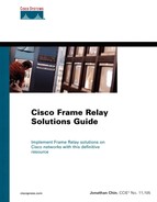
Figure 3-15 shows an example of a Frame Relay network faced with the split horizon problem. In this example, Vulture is a hub router connected to two branch office routers: Raven and Hawk. To conserve IP address space, all three locations are configured to use the 172.16.1.0/29 subnet address. This Frame Relay network is termed as nonbroadcast multiaccess (NBMA) because all locations are configured as nodes on the same IP subnet in a way similar to an Ethernet LAN segment. However, an NBMA Frame Relay network does not support the broadcast capability of a traditional Ethernet LAN.
The three routers are now configured to exchange route information via a distance vector routing protocol such as RIP. Raven and Hawk routers can exchange routing updates directly with Vulture router and vice-versa. However, because of the split horizon issue at Vulture, Vulture is unable to forward routing information learned from Raven to Hawk or from Hawk to Raven. Although Vulture is logically connected to the two remote locations on separate virtual circuits, both virtual circuits are logically multiplexed on the same physical interface. The split horizon rule simply forbids Vulture from sending route information out of an interface if the same route information was learned from the same physical interface.
A workaround to this problem is to have a fully meshed topology by adding a virtual circuit directly between Hawk and Raven routers. In this way, Hawk and Raven routers can exchange route information directly with each other. However, a fully meshed topology increases the operating costs of the network. An alternative solution is to add a separate physical interface on Vulture router so that each remote connection is terminated at the hub location on different hardware. This is not viable because of the added hardware cost. Moreover, this solution would require a different IP subnet address to be used for each virtual connection. Another solution would be to use advanced dynamic link-state routing protocols, which understand the NBMA nature of the Frame Relay network. However, advanced link-state routing protocols, such as Open Shortest Path First (OSPF), place greater demands on the CPU and memory resources of the routers.
In the next section, a more scalable solution using logical software interfaces will be introduced.
On Cisco routers, split horizon is disabled by default for Frame Relay so that routing updates can come in and out of the same interface. However, on partially meshed Frame Relay networks, some protocols, such as IPX, AppleTalk, and transparent bridging, require split horizon in order to work properly.
Cisco routers support the configuration of logical subinterfaces on a physical interface. Configuring subinterfaces allows a single physical interface to be treated as multiple virtual interfaces. This allows the split horizon issues to be overcome. Packets received on one subinterface can be forwarded out another subinterface, even though they are all configured on the same physical interface.
Two different implementations of subinterface types are supported by Cisco routers: point-to-point and multipoint subinterfaces. A subinterface is a logical software interface managed internally by the router. Note that a subinterface uses up memory on the router. The number of subinterfaces that can be configured largely depends on the amount of memory on the router.
Point-to-point subinterfaces allow the physical Frame Relay interface to be partitioned into a number of virtual point-to-point subnetworks. Each point-to-point subnetwork can be assigned its own network number. To the routed protocol, each subinterface appears as if it is located on a separate interface. Routing updates received from one logical point-to-point subinterface can be forwarded out to another logical point-to-point subinterface that is configured under the same physical interface without violating the rule of split horizon. On partially meshed Frame Relay networks, a point-to-point subinterface solves the problem introduced by split horizon. Figure 3-16 shows an example of using point-to-point subinterfaces to overcome split horizon on a partially meshed Frame Relay network.

The second implementation of Frame Relay subinterfaces is the multipoint subinterface. A multipoint subinterface is similar to the physical interface. On Cisco routers, all serial interfaces are multipoint interfaces by default, and multipoint subinterfaces behave exactly like physical interfaces. Both physical and multipoint subinterfaces are subjected to the rule of split horizon. Compared with point-to-point subinterfaces where each point-to-point connection represents a different subnet, multipoint subinterfaces keep all remote sites on a single network. All nodes connected to a multipoint subinterface belong to the same subnet.
One major difference between point-to-point subinterface and multipoint subinterface is that on a point-to-point subinterface, only one DLCI can be assigned to the subinterface. On a multipoint subinterface, multiple DLCIs can be assigned.
Consider an example of multipoint subinterfaces in Figure 3-17. In this example, the Vulture router has a multipoint subinterface configured under its physical interface. Three virtual circuits are terminated at the multipoint subinterface from three different remote locations. As such, the multipoint interface has three DLCIs assigned to uniquely identify the virtual connection belonging to each location. All nodes are placed on the same subnet address. If point-to-point subinterfaces were used, each point-to-point connection would require a separate network layer address.

On Cisco devices, split horizon is enabled or disabled by default, depending on the interface type. Table 3-2 summarizes the default split horizon behavior on Cisco Frame Relay interfaces.
This chapter focused on the important considerations of Frame Relay network planning. Network performance, recurring cost, and future scalability of the network topology are some of the key issues network planners should consider during the network planning and implementation phase. This chapter discussed the different levels of CIR services commonly offered by major service providers. Different Frame Relay topologies were considered, including the advantages and disadvantages associated with each type of topology. This chapter also briefly discussed Frame Relay network performance management. Different methods of improving network performance were introduced, such as controlling network congestion, controlling broadcast traffic, and using advanced queuing mechanisms to prioritize mission-critical traffic. Finally, this chapter presented the concept of Frame Relay subinterfaces supported on the Cisco router and how to effectively overcome the issues created by the split horizon rule. The next chapter will examine the basic configurations of Frame Relay on the Cisco IOS.