By now, readers should recognize the benefits of Quality of Service (QoS) features, such as traffic shaping, traffic policing or queuing, and how these QoS features help to improve the performance of Frame Relay services for mission-critical applications during congestion. Mission-critical traffic, such as Voice over IP (VoIP), is normally classified as higher-priority traffic because its delay-sensitive nature demands an improved level of QoS handling with consistent delay. In general, QoS features allow Frame Relay networks to provide improved and predictable services to mission-critical traffic.
The previous chapters discussed the congestion management QoS features with respect to queuing on Frame Relay networks. This chapter covers the Weighted Random Early Detection (WRED) feature for Frame Relay. WRED is a congestion avoidance QoS feature that provides early detection of congestion on the network. When traffic enters a router, the router, in an effort to avoid congestion, uses WRED to selectively discard packets forwarded on its egress interface as the router begins to experience congestion. The discard policy initiated by WRED can be configured to provide differentiated services for different classes of traffic.
This chapter begins with an overview of the WRED feature in general and explains how WRED can be used to provide congestion avoidance on a Frame Relay virtual circuit. Subsequently, this chapter looks at the Cisco IOS configuration tasks required to enable the WRED feature for a Frame Relay virtual circuit on a Cisco router. At the end of the chapter, the Cisco IOS show commands for monitoring and troubleshooting the WRED feature for Frame Relay networks are explained.
The topics and questions that this chapter addresses include the following:
Overview of WRED
WRED for Frame Relay
Configuring WRED for Frame Relay on a Cisco router
Monitoring and maintaining WRED on a Cisco router
After completing this chapter, readers will recognize the important benefits of WRED. Some of its benefits include providing early detection of congestion on the network and allowing the router to provide differentiated performance and services for different classes of traffic. Readers will become familiar with how WRED can be applied to a Frame Relay network. Following this, readers will learn how to configure WRED for Frame Relay on a Cisco router with the Cisco IOS software. Finally, readers will learn the relevant Cisco IOS show commands for monitoring and maintaining WRED for Frame Relay on a Cisco router.
This section provides an overview of the congestion avoidance mechanisms in the Cisco IOS software. This section also discusses the use and benefits of the supported congestion avoidance features. Congestion avoidance mechanisms help the network to monitor traffic loads and avoid congestion from building up at common network bottlenecks by initiating packet dropping. WRED and Tail Drop are the congestion avoidance techniques currently supported by the Cisco IOS software. WRED allows the network to provide differentiated services and to initiate a drop policy based on the IP precedence values of the packet headers. By contrast, Tail Drop treats all packets equally in its drop policy. Tail Drop and WRED are discussed in detail in subsequent sections. The next section talks about queue size associated with an output queue on an interface and how the size of this queue can be tuned.
In a Cisco router, each interface has a queue size associated with the output queue that indicates the number of packets that the queue can contain. When a router begins to experience congestion, the queue can quickly become congested, and the router has to initiate a drop policy to manage the packets in the queue. The congestion avoidance mechanism enabled on the interface controls the manner in which excess packets are dropped. The supported congestion avoidance mechanisms with regard to packet disposal are Tail Drop and WRED. Tail Drop is the default congestion avoidance mechanism. Tail Drop treats all packets as equal and does not provide differentiated services for different classes of traffic. Tail Drop is explained in the next section.
Every interface on a Cisco router has a default queue size associated with the queuing method used on the interface. The calculated queue size can also vary depending on the platform type. For example, a Fast Ethernet interface on a Cisco router with a bandwidth greater than E1 (2.048 Mbps) uses the default first-in, first-out (FIFO) queuing algorithm on the interface. The default size of the FIFO output queue is 40 packets. This is indicated by the show interface FastEthernet 0/0 command depicted in Example 21-1.
Example 21-1. The show interface Output of a Fast Ethernet Interface
Router#show interface FastEthernet 0/0
FastEthernet0/0 is up, line protocol is up
  Hardware is DEC21140A, address is 0005.0065.fc00 (bia 0005.0065.fc00)
  Internet address is 192.168.1.2/24
  MTU 1500 bytes, BW 100000 Kbit, DLY 100 usec,
     reliability 255/255, txload 1/255, rxload 1/255
  Encapsulation ARPA, loopback not set
  Keepalive set (10 sec)
  Half-duplex, 100Mb/s, 100BaseTX/FX
  ARP type: ARPA, ARP Timeout 04:00:00
  Last input 00:00:03, output 00:00:00, output hang never
  Last clearing of "show interface" counters never
  Input queue: 0/75/0/0 (size/max/drops/flushes); Total output drops: 0
  Queueing strategy: fifo
  Output queue: 0/40 (size/max)
  5 minute input rate 2000 bits/sec, 1 packets/sec
  5 minute output rate 0 bits/sec, 0 packets/sec
     48735 packets input, 14890396 bytes
     Received 47669 broadcasts, 0 runts, 0 giants, 0 throttles
     0 input errors, 0 CRC, 0 frame, 0 overrun, 0 ignored
     0 watchdog
     0 input packets with dribble condition detected
     18358 packets output, 2185553 bytes, 0 underruns
     62 output errors, 1 collisions, 17 interface resets
     0 babbles, 0 late collision, 0 deferred
     62 lost carrier, 0 no carrier
     0 output buffer failures, 0 output buffers swapped out
The size of the output queue on the interface can be tuned with the hold-queue interface configuration command. For other queuing methods, such as CBWFQ and LLQ, the queue size can be adjusted for a particular traffic class defined in the policy-map with the queue-limit command. Generally, when changing the size of the queue, the chosen queue size should not be excessively large or small. A queue with a large size or limit can lead to increased latency from excessive queuing. On the other hand, small queue size can lead to frequent drops, which can result in excessive retransmission at the upper-layer protocols, such as TCP.
Before WRED was supported, Tail Drop was the default congestion avoidance technique on an interface of a Cisco router. With Tail Drop, all packets in the queues are treated equally; Tail Drop does not provide any differentiated treatment to the packets in the queues based on their associated classes of service. When congestion occurs and the queue becomes packed full, Tail Drop initiates packet drops for both high-priority and low-priority traffic without any regard to priority. Tail Drop continues to drop packets from the queues, and the packet drops occur until the congestion in the queues ease and the queues are no longer full. Figure 21-1 illustrates the Tail Drop process on an interface of a Cisco router.
Random Early Detection (RED) is a queue management technique proposed by Sally Floyd and Van Jacobson in the early 1990s. RED is a congestion avoidance method used to manage congestion primarily on TCP/IP networks or on any other transport protocols that can temporarily throttle their transmission rate in response to packet drops. When RED is applied on a router interface, queue thresholds are defined for the output queue on the interface. When the network slowly becomes congested with traffic and the predetermined minimum threshold is exceeded, RED delivers implicit feedback to the TCP transmission source by randomly dropping packets from the queue. TCP detects the packet loss, knows that congestion has occurred, and then drives down its transmission rate. Thus, RED controls the average queue size by randomly dropping packets before the onset of high congestion.
The drop probability is based on the minimum threshold, the maximum threshold, and the mark probability denominator. The rate of packet drop is increased linearly as the average queue size increases until the maximum threshold is hit. The packet drop probability denominator is used to calculate the number of packets dropped when the average queue size is at the maximum threshold. For instance, with a packet drop probability denominator of 10, one out of every ten packets is dropped. Tail Drop still occurs when the average or mean queue size exceeds the maximum drop threshold level.
The effectiveness of RED depends heavily on the abilities of the data transport mechanism. For the most part, the transport protocol must be robust in response to packet loss. Transmission Control Protocol (TCP) has a robust congestion control mechanism, and it can quickly adapt its transmission rate to a tempo that the network can support. TCP can respond to packet loss by lowering its throughput rate with a smaller TCP transmission window one-half of the current size. This is triggered by the TCP back-off algorithm. When the congestion is cleared, TCP slowly increases its output rate but it can exponentially raise its output rate in an extended period of no-congestion. This is known as the TCP slow start algorithm. Most importantly, TCP is the most heavily used network transport protocol in use today and is most effective when used with RED as a congestion avoidance mechanism.
WRED combines IP precedence with RED to provide differentiated treatment for packets with different IP precedence levels. WRED provides early detection of congestion in a similar way to RED, but it extends the capabilities of RED with a method for handling differentiated classes of traffic. WRED provides different maximum and minimum drop threshold levels based on the IP precedence value. Logically, the minimum drop threshold level is higher for traffic with a lower precedence, whereas packets with a higher precedence have a much higher minimum drop threshold level. In such a way, the lower precedence traffic is dropped before the higher precedence traffic becomes affected.
In most typical implementations, WRED is used at the core routers of a network. The edge routers provide a traffic classification function by assigning IP precedences to packets entering the network. The IP precedence values carried by the IP packets reflect the treatment the packets receive at the core routers with WRED.
Example 21-2 shows the WRED default parameters and packet drop statistics on a router interface, after WRED is enabled with the random-detect at the interface level.
Example 21-2. WRED Default Drop Parameters and Statistics
Router#show queueing random-detect
Current random-detect configuration:
  Serial2/2
    Queueing strategy: random early detection (WRED)
    Exp-weight-constant: 9 (1/512)
    Mean queue depth: 39

    Class     Random drop       Tail drop        Minimum   Maximum     Mark
    (Prec)    pkts/bytes        pkts/bytes      threshold threshold probability
        0      504/22176         1068/47114         20        40       1/10
        1        0/0                0/0             22        40       1/10
        2        0/0                0/0             24        40       1/10
        3        0/0                0/0             26        40       1/10
        4        0/0                0/0             28        40       1/10
        5        0/0                0/0             31        40       1/10
        6        0/0                0/0             33        40       1/10
        7        0/0                0/0             35        40       1/10
     rsvp        0/0                0/0             37        40       1/10
Observe in Example 21-2 that with WRED, each class of precedence has different default minimum drop threshold levels. The maximum drop threshold level is equal to the output hold queue size. When congestion builds up at the interface and the mean queue-depth steadily rises to between the maximum and minimum drop thresholds, WRED randomly drops packets that exceed the minimum drop thresholds corresponding to the packets' precedence levels. When the mean queue-depth is equal to the maximum drop threshold, WRED drops packets with a probability equal to the Mark probability. Finally, Tail Drop occurs when the mean queue-depth exceeds the maximum drop threshold. Also take note that when the minimum drop thresholds are configured so that they are all of equal value, WRED becomes the standard RED policy without any differentiated treatments for traffic.
A flow-based WRED is also supported on Cisco routers. Packets are classified into flows, based on parameters such as destination and source addresses and ports. Flow-based WRED maintains the state or count of the number of active flows, which have packets in the output queues. With this value and the output queue size, the number of buffers available per flow can be determined. Once a flow exceeds the per-flow limit, the statistical probability of a packet from the flow being dropped is increased. Flow-based WRED provides a greater fairness with regard to how packets are dropped.
The WRED feature is supported for Frame Relay. It can be configured at the Frame Relay interface level or within the Class-Based Weighted Fair Queuing (CBWFQ) queuing structure based on traffic classes using Modular Quality of Service Command Line Interface (MQC).
On a Frame Relay network, WRED is used as a congestion avoidance policy to offer differentiated service levels to customers. For example, traffic with a precedence level of 0 has a much higher chance of being dropped on a congested connection than “premium” class traffic with a higher precedence level of 4.
Similar to the WRED feature, to avoid congestion, WRED support for Frame Relay depends on a robust higher layer transport protocol to respond to packet loss as an indicator to drop down the transmission rate.
The next section illustrates the main Cisco IOS configuration tasks needed to configure the WRED feature for Frame Relay or within the policy-map structure for enabling WRED with CBWFQ or LLQ.
This section demonstrates the configuration tasks required to enable WRED for Frame Relay. WRED can be configured at the interface level or within the policy-map to initiate the WRED drop mechanism on a per-class basis for CBWFQ or LLQ.
To enable WRED on an interface, use the following commands, beginning in the global configuration mode:
Enter the interface configuration mode of the Frame Relay interface on which you want to enable WRED.
Enable WRED with the random-detect interface configuration command.
(optional) Change the weight factor used in calculating the average queue length with random-detect exponential-weighting-constant exponent. An integer value between 1 and 16 is accepted.
(optional) Use the random-detect precedence precedence min-threshold max-threshold mark-prob-denominator interface configuration command to configure the parameters for packets with a specific IP precedence value. By default, the minimum threshold for IP precedence 0 corresponds to half the maximum threshold for the interface. The default output queue size is 40. Use this command to configure the parameter for each IP precedence value. Note that RED can be enabled by configuring the same values for each IP precedence class.
(optional) To enable flow-based WRED, first enable WRED and then flow-based WRED with random-detect flow interface configuration command. To adjust the flow threshold multiplier, use the random-detect flow average-depth-factor scaling-factor interface configuration command. To adjust the maximum flow count, use the random-detect flow count number interface configuration command.
To enable WRED in a traffic policy within a CBWFQ structure, use the following commands, beginning in global configuration mode:
Enter the policy-map configuration mode by specifying the name of the traffic policy with the policy-map policy-map global configuration command.
In the policy-map, specify the name of traffic class with the class class-name command.
In the policy-map-class configuration mode, enable WRED with the random-detect command.
(optional) You can configure the parameters for IP precedence in WRED or turn on flow-based WRED using the same commands shown in the previous section, which described configuring WRED for the interface.
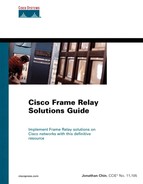
Figure 21-2 shows the network topology used in this scenario to observe the difference between Tail Drop and WRED for Frame Relay.
In Figure 21-2, routers R1 and R2 are connected to a low-speed Frame Relay network. The access speed of the Frame Relay connection is deliberately set to a slow 9600 bps so that congestion can be speedily built up and observed at router R1's egress interface. Two PCs are connected to the LAN segments attached to the routers, as shown in the diagram. The PCs are running a TCP Session Emulator application. One of them simulates a TCP client, and the other acts as a TCP server. When the Frame Relay is up and running, TCP connections are established between the PCs. This creates the TCP traffic required to achieve congestion, allowing the observation of WRED and Tail Drop in action.
The configurations of the routers in Figure 21-2 are shown in Example 21-3.
Example 21-3. Configurations of the Routers in Figure 21-2
! Router R1

<output omitted>

interface FastEthernet0/0
 ip address 10.0.0.1 255.255.255.0
!
interface Serial4/3
 no ip address
 encapsulation frame-relay
 no fair-queue
!
interface Serial4/3.102 point-to-point
 ip address 172.16.1.1 255.255.255.252
 frame-relay interface-dlci 102
!
router eigrp 1
 network 10.0.0.0 0.0.0.255
 network 172.16.1.0 0.0.0.3
 no auto-summary

! Router R2

<output omitted>

interface FastEthernet0/1
 ip address 10.0.1.1 255.255.255.0
!
interface Serial2/2
 no ip address
 encapsulation frame-relay
 no fair-queue
!
interface Serial2/2.201 point-to-point
 ip address 172.16.1.2 255.255.255.252
 frame-relay interface-dlci 201
!
router eigrp 1
 network 10.0.1.0 0.0.0.255
 network 172.16.1.0 0.0.0.3
 no auto-summary
The TCP Session Emulator running at the PCs is used to generate TCP traffic onto the network to emulate TCP session flows between a TCP client and a TCP server. The dozens of TCP connections initiated are sufficient to flood the slow 9.6 kbps Frame Relay link.
In the next section, when the TCP sessions are initiated between the PCs, observe the behavior of Tail Drop and WRED in response to a spike in traffic on router R2's serial interface.
The show interface privileged EXEC mode command can be used to display the queuing strategy used on the interface, as shown in Example 21-4.
Example 21-4. Output of show interface Command on Router R2
R2#show interface serial2/2
Serial2/2 is up, line protocol is up
  Hardware is CD2430 in sync mode
  MTU 1500 bytes, BW 128 Kbit, DLY 20000 usec,
     reliability 255/255, txload 11/255, rxload 1/255
  Encapsulation FRAME-RELAY, loopback not set
  Keepalive set (10 sec)
  LMI enq sent  123, LMI stat recvd 123, LMI upd recvd 0, DTE LMI up
  LMI enq recvd 0, LMI stat sent  0, LMI upd sent  0
  LMI DLCI 1023  LMI type is CISCO  frame relay DTE
  FR SVC disabled, LAPF state down
  Broadcast queue 0/64, broadcasts sent/dropped 286/0, interface broadcasts 266
  Last input 00:00:01, output 00:00:01, output hang never
  Last clearing of "show interface" counters 00:20:29
  Queueing strategy: fifo
  Output queue 0/40, 6107 drops; input queue 0/75, 0 drops
  5 minute input rate 0 bits/sec, 5 packets/sec
  5 minute output rate 6000 bits/sec, 21 packets/sec
     8524 packets input, 389129 bytes, 0 no buffer
     Received 0 broadcasts, 0 runts, 0 giants, 0 throttles
     0 input errors, 0 CRC, 0 frame, 0 overrun, 0 ignored, 0 abort
     26433 packets output, 1174563 bytes, 0 underruns
     0 output errors, 0 collisions, 3 interface resets
     0 output buffer failures, 0 output buffers swapped out
     2 carrier transitions
     DCD=up  DSR=up  DTR=up  RTS=up  CTS=up
As shown in Example 21-4, FIFO is the queuing strategy in use, and the default output queue size is 40 packets.
Alternatively, the show queueing interface interface-number privileged EXEC mode command can be used to display the queuing strategy used on the interface. The shorter form of the command, show queueing, displays a summary of the queuing strategies in use by all interfaces on the router. Example 21-5 and Example 21-6 show the output of show queueing interface and show queueing, respectively.
Example 21-5. Output of show queueing interface Command
R2#show queueing interface serial2/2
Interface Serial2/2 queueing strategy: none
Example 21-6. Output of show queueing Command
R2#show queueing
Current fair queue configuration:

  Interface           Discard     Dynamic      Reserved
                      threshold   queue count  queue count
  Serial0/0           64          256          0
  Serial0/1           64          256          0
  Serial2/0           64          32           0
  Serial2/1           64          32           0
  Serial2/3           64          256          0
  Serial2/4           64          32           0
  Serial2/5           64          32           0
  Serial2/6           64          32           0
  Serial2/7           64          32           0

Current DLCI priority queue configuration:
Current priority queue configuration:
Current custom queue configuration:
Current random-detect configuration:
TCP sessions are now initiated between the TCP client and TCP server, and the behavior of Tail Drop and WRED are observed. Example 21-7 shows the output of show interface on router R2 after the TCP sessions are started.
Example 21-7. Output of show interface Command on Router R2 for Tail Drop
R2#show interface serial2/2
Serial2/2 is up, line protocol is up
  Hardware is CD2430 in sync mode
  MTU 1500 bytes, BW 128 Kbit, DLY 20000 usec,
     reliability 255/255, txload 15/255, rxload 5/255
  Encapsulation FRAME-RELAY, loopback not set
  Keepalive set (10 sec)
  LMI enq sent  23, LMI stat recvd 23, LMI upd recvd 0, DTE LMI up
  LMI enq recvd 0, LMI stat sent  0, LMI upd sent  0
  LMI DLCI 1023  LMI type is CISCO  frame relay DTE
  FR SVC disabled, LAPF state down
  Broadcast queue 0/64, broadcasts sent/dropped 54/0, interface broadcasts 50
  Last input 00:00:00, output 00:00:00, output hang never
  Last clearing of "show interface" counters 00:03:53
  Queueing strategy: fifo
  Output queue 31/40, 1642 drops; input queue 0/75, 0 drops
  5 minute input rate 3000 bits/sec, 7 packets/sec
  5 minute output rate 8000 bits/sec, 24 packets/sec
     1960 packets input, 89843 bytes, 0 no buffer
     Received 0 broadcasts, 0 runts, 0 giants, 0 throttles
     0 input errors, 0 CRC, 0 frame, 0 overrun, 0 ignored, 0 abort
     5705 packets output, 254216 bytes, 0 underruns
     0 output errors, 0 collisions, 0 interface resets
     0 output buffer failures, 0 output buffers swapped out
     0 carrier transitions
     DCD=up  DSR=up  DTR=up  RTS=up  CTS=up
As observed in the output of the show interface command in Example 21-7, congestion has kicked in on interface serial2/2 on router R2. This is because an aggregate traffic throughput of approximately 11000 bps (33 packets per second in both ingress and egress directions) has been put onto the slow 9600 bps Frame Relay link. A large number of packets have been tail dropped from the output queue.
Next, WRED is activated on router R2's egress interface serial2/2 with the random-detect interface configuration command. When WRED is configured at the interface level, WRED acts on the Frame Relay interface. Then again, if CBWFQ is used, WRED can be configured with class-map inside the policy-map to use WRED as the congestion avoidance method for the specified class of traffic.
The counters on router R2 are cleared with the clear counter command, and the same TCP session configuration between the client and server PCs is restarted. Example 21-8 shows the output of the show interface command, and Example 21-9 shows the output of the show queueing random-detect command.
Example 21-8. Output of show interface Command on Router R2 for WRED
R2#show interface serial2/2
Serial2/2 is up, line protocol is up
  Hardware is CD2430 in sync mode
  MTU 1500 bytes, BW 128 Kbit, DLY 20000 usec,
     reliability 255/255, txload 15/255, rxload 5/255
  Encapsulation FRAME-RELAY, loopback not set
  Keepalive set (10 sec)
  LMI enq sent  24, LMI stat recvd 24, LMI upd recvd 0, DTE LMI up
  LMI enq recvd 0, LMI stat sent  0, LMI upd sent  0
  LMI DLCI 1023  LMI type is CISCO  frame relay DTE
  FR SVC disabled, LAPF state down
  Broadcast queue 0/64, broadcasts sent/dropped 55/0, interface broadcasts 51
  Last input 00:00:00, output 00:00:00, output hang never
  Last clearing of "show interface" counters 00:03:57
  Input queue: 0/75/0/0 (size/max/drops/flushes); Total output drops: 1605
  Queueing strategy: random early detection(RED)
  5 minute input rate 3000 bits/sec, 8 packets/sec
  5 minute output rate 7000 bits/sec, 23 packets/sec
     1954 packets input, 88628 bytes, 0 no buffer
     Received 0 broadcasts, 0 runts, 0 giants, 0 throttles
     0 input errors, 0 CRC, 0 frame, 0 overrun, 0 ignored, 0 abort
     5778 packets output, 256362 bytes, 0 underruns
     0 output errors, 0 collisions, 0 interface resets
     0 output buffer failures, 0 output buffers swapped out
     0 carrier transitions
     DCD=up  DSR=up  DTR=up  RTS=up  CTS=up
Example 21-9. Output of show queueing random-detect Command on Router R2
R2#show queueing random-detect
Current random-detect configuration:
  Serial2/2
    Queueing strategy: random early detection (WRED)
    Exp-weight-constant: 9 (1/512)
    Mean queue depth: 39

    Class     Random drop       Tail drop        Minimum   Maximum     Mark
    (Prec)    pkts/bytes        pkts/bytes      threshold threshold probability
        0      504/22176         1068/47114         20        40       1/10
        1        0/0                0/0             22        40       1/10
        2        0/0                0/0             24        40       1/10
        3        0/0                0/0             26        40       1/10
        4        0/0                0/0             28        40       1/10
        5        0/0                0/0             31        40       1/10
        6        0/0                0/0             33        40       1/10
        7        0/0                0/0             35        40       1/10
     rsvp        0/0                0/0             37        40       1/10
The output of the show interface command in Example 21-8 now indicates that the queuing strategy used is RED.
In these observations, WRED starts dropping packets randomly within the first 10 seconds after the onset of TCP traffic. This happens when the mean queue-depth exceeds the minimum drop threshold level. On the other hand, Tail Drop discards packets only after the output hold queue is fully congested. With Tail Drop, packet drops are observed at the interface after approximately 15 seconds. By randomly dropping packets from the queue, WRED distributes the packet losses in time and absorbs the spikes. With sustained congestion, the mean queue-depth eventually exceeds the maximum drop threshold level, and WRED uses Tail Drop until the mean queue-depth falls below the maximum drop threshold level again. This is shown in Example 21-9.
Finally, notice again in the output of Example 21-9, all the packets dropped by WRED fall under the class precedence 0. By default, all untagged traffic has IP precedence 0. However, when the router R2 receives packets tagged with different classes of services on the congested interface (by means of different IP precedence levels), packets with a higher precedence have a lower chance of being dropped when compared with packets with a lower precedence.
This chapter talked about the congestion avoidance techniques supported on Cisco routers to monitor and manage traffic loads and to avoid congestion at the network bottlenecks. By dropping packets, Tail Drop and RED provide the means to avoid congestion.
Tail Drop, the default congestion avoidance mechanism if WRED is not enabled, treats all packets equally without providing any differentiated services between the different classes of traffic. Tail Drop discards packets from the output queue when the queue becomes filled.
By contrast, the WRED congestion avoidance technique allows the router to selectively discard packets based on the IP precedence values assigned to the packets when the router begins to experience congestion. WRED provides differentiated treatment for different classes of service. Normally, it ensures that the standard or low-priority packets are discarded before the higher-priority packets. In a Frame Relay environment, WRED can be applied to the main interface or directly to a Frame Relay PVC with CBWFQ or LLQ in a policy-map.
This chapter also discussed the Cisco IOS configuration tasks required to enable Tail Drop and WRED for Frame Relay on a Cisco router. Then this chapter demonstrated the relevant Cisco IOS show commands for monitoring and maintaining Tail Drop and WRED for Frame Relay on Cisco routers.
In the next chapter, the Resource Reservation Protocol (RSVP) Support for Frame Relay feature is discussed.
Cisco IOS 12.1 Release Documentation, Congestion Avoidance Overview: http://www.cisco.com/univercd/cc/td/doc/product/software/ios121/121cgcr/qos_c/qcprt3/qcdconav.htm
Cisco IOS 12.1(5)T Release Documentation, DiffServ Compliant Weighted Random Early Detection: http://www.cisco.com/univercd/cc/td/doc/product/software/ios121/121newft/121t/121t5/dtdswred.htm