Chapter 5, “Frame Relay Traffic Shaping,” introduced the principal congestion control mechanism for managing Frame Relay traffic on Cisco routers. This chapter discusses the Adaptive Frame Relay Traffic Shaping for Interface Congestion feature, which is essentially an enhancement feature to the Frame Relay Traffic Shaping functionality. This chapter explains the purpose of the feature and its benefits and introduces the Cisco IOS configuration and monitoring commands in a case study.
The topics and questions that this chapter addresses include the following:
Overview of the Adaptive Frame Relay Traffic Shaping for Interface Congestion feature
The benefits of the Adaptive Frame Relay Traffic Shaping for Interface Congestion feature
Configuring Adaptive Frame Relay Traffic Shaping for Interface Congestion on a Cisco router
Verifying Adaptive Frame Relay Traffic Shaping for Interface Congestion configurations on a Cisco router
Case studies on the Adaptive Frame Relay Traffic Shaping for Interface Congestion feature
After completing this chapter, readers will be able to recognize the benefits of the Adaptive Frame Relay Traffic Shaping for Interface Congestion feature. Readers will become familiar with how the feature works and how it controls congestion at the interface level. Readers will learn how to configure the feature on a Cisco router. Readers will be able to use Cisco IOS show commands to monitor and maintain the configurations of the feature on a Cisco router.
This section describes the requirements and the purpose of the Adaptive Frame Relay Traffic Shaping for Interface Congestion feature. But first, it is important to understand fully the queuing mechanisms employed by Frame Relay interfaces configured on Cisco routers to appreciate the benefits of the Adaptive Frame Relay Traffic Shaping for Interface Congestion feature.
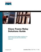
When Frame Relay encapsulation is configured on a Cisco router interface, a hierarchical queuing mechanism involving two different levels is set up: one at the virtual circuit (VC) and another at the interface level. When congestion builds up in the Frame Relay network, outgoing Frame Relay packets waiting to be transmitted by the router can be queued up in the two different levels of queues before they are eventually sent out from the egress interface onto the wire.
As explained in Chapter 5, the queuing methods supported by the Frame Relay Traffic Shaping feature are custom, priority, or default First-In-First-Out (FIFO) queuing. They are applied at the VC level by configuring a Frame Relay map-class. The configured Frame Relay map class is then applied to a DLCI using the frame-relay class class-name or class class-name command. The frame-relay class class-name command can be used to associate a Frame Relay map class with a physical serial interface or a multipoint Frame Relay subinterface. Once associated, all Frame Relay PVCs created on the physical serial interface or multipoint subinterface inherit the configuration parameters configured in the map class. On the other hand, the class class-name command under the DLCI configuration mode should be used when associating a Frame Relay map class directly with a DLCI.
NOTE
The latest Cisco IOS software releases now allow Frame Relay Traffic Shaping to support advanced queuing mechanisms such as Class-Based Weighted Fair Queuing (CBWFQ) and Low Latency Queuing (LLQ). CBWFQ and other advanced queuing strategies are discussed in Part IV, “Cisco Frame Relay Solutions for Congestion Management,” later in this book.
When congestion occurs in the Frame Relay network, outgoing Frame Relay packets waiting for delivery on a DLCI are queued on the VC level queues that are applied to the particular DLCI. Subsequently, the queued Frame Relay packets are removed from the VC level queues and sent to the egress interface for transmission. If the egress interface buffer is temporarily full and unable to handle the transmission of packets, the packets are further held up in the interface level queues waiting for their turn or are eventually dropped. This process is illustrated in Figure 9-1.
The Frame Relay Traffic Shaping feature is applied only at the main interface level of a Cisco router. The use of the Frame Relay Traffic Shaping feature forbids other queuing mechanisms from being used at the interface level. When Frame Relay Traffic Shaping is enabled, the queuing strategy at the interface has to be strictly FIFO. FIFO queuing, as its name implies, removes packets from a queue based on their order of arrival.
With oversubscription of bandwidth, the congestion level built up can cause the interface queue to be speedily filled. This happens when the sum of the committed information rate (CIR) of each VC under the Frame Relay interface exceeds the actual interface physical rate. When this condition is prolonged, the interface queue starts to drop packets. Because the packets dropped at the interface level might have been queued according to user-defined priority levels using priority queuing (PQ) applied at the DLCI level, dropping packets at the interface level results in a waste of the queuing efforts performed earlier. Therefore, it becomes necessary to shape the VC to a CIR lower than the access rate so that user data is queued and dropped at the DLCI level if necessary.
The Adaptive Frame Relay Traffic Shaping for Interface Congestion feature handles congestion at the physical serial interface level. Adaptive Frame Relay Traffic Shaping for Interface Congestion is one of the effective Frame Relay solutions that are used to alleviate congestion built up at the interface. Cisco developed the Adaptive Frame Relay Traffic Shaping for Interface Congestion feature as an enhancement to the Frame Relay Traffic Shaping feature discussed in Chapter 5. The main purpose of Adaptive Frame Relay Traffic Shaping for Interface Congestion is to dynamically throttle the VC egress rate when congestion is detected at the interface queue. When congestion eases, it dynamically adjusts the VC egress rate on the VC based on the congestion level in the interface queue. When the interface experiences congestion, Adaptive Frame Relay Traffic Shaping for Interface Congestion helps to ensure packet drops occur early at the VC queues, rather than being delayed or dropped eventually at the interface queue.
NOTE
The Adaptive Frame Relay Traffic Shaping for Interface Congestion feature is a Cisco-specific feature and it is available in Cisco IOS Release 12.2(4)T and later.
When the feature is enabled, the traffic shaping mechanism actively monitors the congestion condition in the interface queue. This feature complements the Frame Relay Traffic Shaping feature by reducing the output rates of all the VCs to their MINCIR (Minimum CIR) value when the congestion level in the interface queue exceeds a configured threshold, known as the queue depth. When the congestion level in the interface queue is above the configured queue depth, Adaptive Frame Relay Traffic Shaping for Interface Congestion throttles the VC egress rate from CIR to MINCIR. When the congestion level in the interface queue falls below the queue depth, the traffic shaping mechanism increases the output rate of all the VCs back to their CIR rate.
This process serves many benefits. First, it guarantees the MINCIR for all VCs on the interface during sustained periods of congestions. Second, it reduces packet drops taking place at the interface queue by throttling down the output rates of the VCs when there is a sign of the interface queues getting congested (via the user configured queue depth). Finally, before the release of this feature, Frame Relay packets fragmented by FRF.12 function were susceptible to packet drops at the interface queue. FRF.12 belongs to the Frame Relay Forum's Implementation Agreement for the fragmentation of Frame Relay frames. Any dropped fragment resulted in the whole frame being unusable and the end stations having to retransmit the entire frame. When the feature is used together with FRF.12 Frame Relay Fragmentation (applicable at the DLCI level), it ensures that packet drops occur early in the VC queues before any fragmentation occurs.
NOTE
This feature requires the sum of the MINCIR values (default to 56 kbps) for all VCs on the interface to be lower than the interface bandwidth.
The Adaptive Frame Relay Traffic Shaping feature is configured with a Frame Relay map class, and the default behavior for the feature is disabled. If a VC does not have a Frame Relay map class associated with it, or the map class attached to the DLCI does not have interface congestion configured, the PVC does not react to the congestion level marked by the queue depth in the interface queue.
The size of the queue depth is user-configurable, and the acceptable value for queue depth ranges from 0 to 40. If the queue depth is not configured, it defaults to 0, which essentially means all the VCs associated with the map class always send at their configured MINCIR values.
After the feature is fully enabled (by configuring the map class and associating it with the DLCI), the shaping mechanism actively measures the queue depth of the interface queue and drops the output rate of the VC to its MINCIR once the queue depth is exceeded. When the number of packets in the interface queue drops below the configured queue depth, the shaping mechanism allows the VC to send at its CIR again. Compared with the slow start mechanism in adaptive traffic shaping to BECN or ForeSight, this swiftly avoids any underutilization of the link.
The feature allows interoperability with adaptive shaping to BECN or ForeSight functionality. If interface congestion exceeds the queue depth when Adaptive Frame Relay Traffic Shaping for Interface Congestion is enabled together with adaptive shaping to BECN or ForeSight, the PVC output rate is reduced to its MINCIR value. When the interface congestion drops below the configured queue depth, the PVC output rate reacts to adaptive shaping to BECN or ForeSight and is adjusted according to BECN tagged packets or ForeSight messages received.
The flow diagram for the Adaptive Frame Relay Traffic Shaping for Interface Congestion feature is depicted in Figure 9-2.

NOTE
The Adaptive Frame Relay Traffic Shaping for Interface Congestion feature is supported on terminated and switched PVCs only. Switched virtual circuits (SVCs) are not supported by the feature. In addition, the current supported Cisco router platforms are the c2500, c2600, c3600, and c7200 series routers.
The Frame Relay Traffic Shaping feature must be enabled on the interface in order to use Adaptive Frame Relay Traffic Shaping for Interface Congestion. Refer to Chapter 5 for the configuration tasks required to enable Frame Relay Traffic Shaping.
To configure Adaptive Frame Relay Traffic Shaping for Interface Congestion, perform the configuration steps listed below:
Enter the interface configuration mode of the serial interface and enable Frame Relay encapsulation with the encapsulation frame-relay command.
Enable Frame Relay traffic shaping on the main interface with the frame-relay traffic-shaping interface configuration command.
Configure a Frame Relay map class using the frame-relay map-class map-class-name global configuration command.
Enable Adaptive Frame Relay Traffic Shaping for Interface Congestion and set the queue depth with the frame-relay adaptive-shaping interface-congestion [queue-depth]. The valid range for queue-depth is 0 to 40. If queue-depth is not specified, the default value is 0.
A configuration example of Adaptive Frame Relay Traffic Shaping for Interface Congestion is shown in Example 9-1. Examples are based on the topology diagram shown in Figure 9-3 to explain the configuration commands and the functionalities of the feature.
Example 9-1. Sample Configurations of Adaptive Frame Relay Traffic Shaping for Interface Congestion Based on Figure 9-3
! R1
interface Serial3
 no ip address
 encapsulation frame-relay
 clockrate 128000
!
interface Serial3.100 point-to-point
 ip address 192.168.1.1 255.255.255.0
 no ip route-cache
 frame-relay interface-dlci 100

!R2
frame-relay switching
!
interface Serial3/3
 no ip address
 encapsulation frame-relay
 frame-relay interface-dlci 100 switched
  load-interval 30
 frame-relay intf-type dce
!
interface Serial3/1
 no ip address
 encapsulation frame-relay
 no fair-queue
 frame-relay traffic-shaping
 frame-relay interface-dlci 200 switched
  class FRTS
  load-interval 30
 frame-relay intf-type dce
!
map-class frame-relay FRTS
 frame-relay cir 112000
 frame-relay bc 14000
 frame-relay mincir 56000
 frame-relay adaptive-shaping interface-congestion 10
connect FRTS Serial3/3 100 Serial3/1 200

!R3
interface Serial1/1
 no ip address
 encapsulation frame-relay
 clockrate 128000
!
interface Serial1/1.200 point-to-point
 ip address 192.168.1.2 255.255.255.0
 frame-relay interface-dlci 200
In Example 9-1, the frame-relay adaptive-shaping interface-congestion 10 map-class configuration command is configured under the Frame Relay map class named FRTS on R2. The map class FRTS is attached to switched DLCI 200 under interface serial3/1. The queue depth is chosen to be 10 packets.
The show frame-relay pvc command can be used to verify that Adaptive Frame Relay Traffic Shaping for Interface Congestion is enabled for the DLCI. This is shown in Example 9-2.
Example 9-2. Sample Output of show frame-relay pvc Command at R2
R2#show frame-relay pvc 200

PVC Statistics for interface Serial3/1 (Frame Relay DCE)

DLCI = 200, DLCI USAGE = SWITCHED, PVC STATUS = ACTIVE, INTERFACE = Serial3/1

  input pkts 102           output pkts 65           in bytes 10561
  out bytes 7740           dropped pkts 0           in pkts dropped 0
  out pkts dropped 0                out bytes dropped 0
  in FECN pkts 0           in BECN pkts 0           out FECN pkts 0
  out BECN pkts 0          in DE pkts 0             out DE pkts 0
  out bcast pkts 0         out bcast bytes 0
  30 second input rate 0 bits/sec, 0 packets/sec
  30 second output rate 0 bits/sec, 0 packets/sec
  switched pkts 102
  Detailed packet drop counters:
  no out intf 0            out intf down 0          no out PVC 0
  in PVC down 0            out PVC down 0           pkt too big 0
  shaping Q full 0         pkt above DE 0           policing drop 0
  pvc create time 00:17:58, last time pvc status changed 00:17:19
  cir 112000    bc 14000     be 0         byte limit 1750   interval 125
  mincir 56000     byte increment 1750  Adaptive Shaping IF_CONG
  pkts 66        bytes 8037      pkts delayed 0         bytes delayed 0
  shaping inactive
  traffic shaping drops 0
  Queueing strategy: fifo
Output queue 0/40, 0 drop, 0 dequeued
In Example 9-2, observe the keyword Adaptive Shaping IF_CONG in the show frame-relay pvc 200 output. The output tells you that Adaptive Frame Relay Traffic Shaping for Interface Congestion has been enabled for DLCI 200. Also notice that “shaping inactive” is in the show frame-relay pvc 200 output. This indicates that the frame-relay traffic-shaping command has been enabled on the main interface serial3/1, but shaping is currently inactive due to the absence of traffic.
The show interface serial type/number global EXEC command can also be used to verify that Adaptive Frame Relay Traffic Shaping for Interface Congestion is working properly. If the feature is functioning correctly, the number of packets in the output queue should be equal to or close to the configured queue depth.
Example 9-3. Sample Output of show interface Command
R2#show inter serial3/1
Serial3/1 is up, line protocol is up
  Hardware is M4T
  MTU 1500 bytes, BW 1544 Kbit, DLY 20000 usec,
     reliability 255/255, txload 1/255, rxload 1/255
  Encapsulation FRAME-RELAY, crc 16, loopback not set
  Keepalive set (10 sec)
  Restart-Delay is 0 secs
  LMI enq sent  0, LMI stat recvd 0, LMI upd recvd 0
  LMI enq recvd 159, LMI stat sent  159, LMI upd sent  0, DCE LMI up
  LMI DLCI 1023  LMI type is CISCO  frame relay DCE
  FR SVC disabled, LAPF state down
  Broadcast queue 0/64, broadcasts sent/dropped 0/0, interface      broadcasts 0
  Last input 00:00:00, output 00:00:00, output hang never
  Last clearing of "show interface" counters 00:27:34
  Input queue: 0/75/0/0 (size/max/drops/flushes); Total output drops: 0
  Queueing strategy: fifo
  Output queue :0/40 (size/max)
  5 minute input rate 0 bits/sec, 0 packets/sec
  5 minute output rate 0 bits/sec, 0 packets/sec
     270 packets input, 16165 bytes, 0 no buffer
     Received 0 broadcasts, 0 runts, 0 giants, 0 throttles
     0 input errors, 0 CRC, 0 frame, 0 overrun, 0 ignored, 0 abort
     234 packets output, 13001 bytes, 0 underruns
     0 output errors, 0 collisions, 2 interface resets
     0 output buffer failures, 0 output buffers swapped out
     5 carrier transitions     DCD=up  DSR=up  DTR=up  RTS=up  CTS=up
This chapter presented the Adaptive Frame Relay Traffic Shaping for Interface Congestion enhancement feature. This feature is an improvement to the Frame Relay Traffic Shaping feature, allowing Frame Relay users who oversubscribe their Frame Relay connections to effectively manage congestion and packet drops at the routers' interface level. The feature provides an early warning by detecting the congestion condition in the interface queue and ensuring that packets are dropped early at the VC queues in times of congestion. In a Frame Relay network, this feature is useful with Frame Relay Traffic Shaping if congestion or oversubscription is fairly common on the network.
This chapter explained the configuration tasks and the Cisco IOS configuration commands involved in configuring the Adaptive Frame Relay Traffic Shaping for Interface Congestion feature on a Cisco router. In addition, this chapter presented the useful Cisco IOS show commands for monitoring and maintaining the feature. Finally, the case study sections in this chapter present an example of an application for the Adaptive Frame Relay Traffic Shaping for Interface Congestion feature.
The next chapter discusses the Point-to-Point Protocol over Frame Relay feature.
Cisco IOS Release 12.2(4)T - Adaptive Frame Relay Traffic Shaping for Interface Congestion: http://www.cisco.com/univercd/cc/td/doc/product/software/ios122/122newft/122t/122t4/ft_afrts.htm
This section uses the configuration setup in Example 9-1 to demonstrate the interface congestion condition at R2 when Adaptive Frame Relay Traffic Shaping for Interface Congestion is not enabled. The difference in performance with and without enabling Adaptive Frame Relay Traffic Shaping for Interface Congestion is compared. The contrast in performance is between intelligent packet drops occurring at the VC level and packet drops happening at the interface level.
R1 is configured to send a continuous stream of traffic to R3 via R2 at a rate of 128 kbps. R2 is set up with a CIR of 112 kbps. Notice that the upstream DLCI 100 has twice the bandwidth capacity compared with the downstream DLCI 200. This simulates a bandwidth mismatch commonly seen in a hub-and-spoke topology. It is used to create a bottleneck so that congestion can build up at R2. The configured traffic rate of 128 kbps is sufficient to generate a congestion condition in R2's outgoing interface along the data path.
Example 9-4 shows the configuration file of R2. Notice that the frame-relay adaptive-shaping interface-congestion 10 command configured in the map class earlier has been omitted.
Example 9-4. Configuration of R2 Without Adaptive Frame Relay Traffic Shaping for Interface Congestion
frame-relay switching
!
interface Serial3/3
 no ip address
 encapsulation frame-relay
 frame-relay interface-dlci 100 switched
  load-interval 30
 frame-relay intf-type dce
!
interface Serial3/1
 no ip address
 encapsulation frame-relay
 no fair-queue
 frame-relay traffic-shaping
 frame-relay interface-dlci 200 switched
  class FRTS
  load-interval 30
 frame-relay intf-type dce
!
map-class frame-relay FRTS
 frame-relay cir 112000
 frame-relay bc 14000
 frame-relay mincir 56000
connect FRTS Serial3/3 100 Serial3/1 200
The traffic stream is sent from R1. Example 9-5 shows the output of the show interface command at R2 after 5 minutes.
Example 9-5. show interface Output of R2 Without Enabling Adaptive Frame Relay Traffic Shaping for Interface Congestion
R2#show interface s3/1
Serial3/1 is up, line protocol is up
  Hardware is M4T
  MTU 1500 bytes, BW 1544 Kbit, DLY 20000 usec,
     reliability 255/255, txload 11/255, rxload 1/255
  Encapsulation FRAME-RELAY, crc 16, loopback not set
  Keepalive set (10 sec)
  Restart-Delay is 0 secs
  LMI enq sent  0, LMI stat recvd 0, LMI upd recvd 0
  LMI enq recvd 12, LMI stat sent  12, LMI upd sent  0, DCE LMI up
  LMI DLCI 1023  LMI type is CISCO  frame relay DCE
  FR SVC disabled, LAPF state down
  Broadcast queue 0/64, broadcasts sent/dropped 0/0, interface broadcasts 0
  Last input 00:00:04, output 00:00:00, output hang never
  Last clearing of "show interface" counters 00:02:04
  Input queue: 0/75/0/0 (size/max/drops/flushes); Total output drops: 700
  Queueing strategy: fifo
  Output queue :40/40 (size/max)
  5 minute input rate 0 bits/sec, 0 packets/sec
  5 minute output rate 72000 bits/sec, 9 packets/sec
     14 packets input, 942 bytes, 0 no buffer
     Received 0 broadcasts, 0 runts, 0 giants, 0 throttles
     0 input errors, 0 CRC, 0 frame, 0 overrun, 0 ignored, 0 abort
     1156 packets output, 1143469 bytes, 0 underruns
     0 output errors, 0 collisions, 0 interface resets
     0 output buffer failures, 0 output buffers swapped out
0 carrier transitions     DCD=up  DSR=up  DTR=up  RTS=up  CTS=up
Example 9-6 depicts the output of the show frame-relay pvc 200 command on router R2, which does not have Adaptive Frame Relay Traffic Shaping for Interface Congestion enabled.
Example 9-6. show frame-relay pvc Output Without Enabling Adaptive Frame Relay Traffic Shaping for Interface Congestion
R2#show frame-relay pvc 200

PVC Statistics for interface Serial3/1 (Frame Relay DCE)

DLCI = 200, DLCI USAGE = SWITCHED, PVC STATUS = ACTIVE, INTERFACE = Serial3/1

  input pkts 4             output pkts 3023         in bytes 1572
  out bytes 3021594        dropped pkts 327         in pkts dropped 0
  out pkts dropped 327              out bytes dropped 326297
  late-dropped out pkts 327         late-dropped out bytes 326297
  in FECN pkts 0           in BECN pkts 0           out FECN pkts 0
  out BECN pkts 0          in DE pkts 0             out DE pkts 0
  out bcast pkts 0         out bcast bytes 0
  30 second input rate 0 bits/sec, 0 packets/sec
  30 second output rate 111000 bits/sec, 14 packets/sec
  switched pkts 4
  Detailed packet drop counters:
  no out intf 0            out intf down 0          no out PVC 0
  in PVC down 0            out PVC down 0           pkt too big 0
  shaping Q full 327       pkt above DE 0           policing drop 0
  pvc create time 04:13:25, last time pvc status changed 04:08:55
  cir 112000    bc 112000    be 0         byte limit 1750   interval 125
  mincir 32000     byte increment 1750  Adaptive Shaping none
  pkts 2998      bytes 2996594   pkts delayed 2988      bytes delayed 2986594
  shaping active
  traffic shaping drops 0
  Queueing strategy: fifo
  Output queue 39/40, 331 drop, 3002 dequeued
The results clearly indicate that without Adaptive Frame Relay Traffic Shaping for Interface Congestion, the Frame Relay router is unable to control packet drops occurring at the interface level. Although Frame Relay Traffic Shaping is able to perform rate limiting and to control the output rate at the CIR value, it is unable to prevent congestion from taking place at the queues. This is particularly true when the Frame Relay network is heavily oversubscribed.
Although Adaptive Frame Relay Traffic Shaping with BECN or ForeSight is effective, it depends on the ability of the Frame Relay switch or network to respond to the congestion and send BECN tagged packets or ForeSight messages.
The frame-relay adaptive-shaping interface-congestion 10 command is now configured under the Frame Relay map-class associated with DLCI 200. Example 9-7 shows the condition at R2's outgoing serial interface after 5 minutes of traffic is sent from R1.
Example 9-7. show interface Output at R2
Upstream interface at R2:

R2#show interface serial3/3
Serial3/3 is up, line protocol is up
  Hardware is M4T
  MTU 1500 bytes, BW 1544 Kbit, DLY 20000 usec,
     reliability 255/255, txload 1/255, rxload 20/255
  Encapsulation FRAME-RELAY, crc 16, loopback not set
  Keepalive set (10 sec)
  Restart-Delay is 0 secs
  LMI enq sent  0, LMI stat recvd 0, LMI upd recvd 0
  LMI enq recvd 51, LMI stat sent  51, LMI upd sent  0, DCE LMI up
  LMI DLCI 1023  LMI type is CISCO  frame relay DCE
  FR SVC disabled, LAPF state down
  Broadcast queue 0/64, broadcasts sent/dropped 0/0, interface broadcasts 0
  Last input 00:00:05, output 00:00:05, output hang never
  Last clearing of "show interface" counters 00:08:30
  Input queue: 0/75/0/0 (size/max/drops/flushes); Total output drops: 0
  Queueing strategy: weighted fair
  Output queue: 0/1000/64/0 (size/max total/threshold/drops)
     Conversations  0/1/256 (active/max active/max total)
     Reserved Conversations 0/0 (allocated/max allocated)
     Available Bandwidth 1158 kilobits/sec
  5 minute input rate 124000 bits/sec, 15 packets/sec
  5 minute output rate 0 bits/sec, 0 packets/sec
     7701 packets input, 7644336 bytes, 0 no buffer
     Received 0 broadcasts, 0 runts, 0 giants, 0 throttles
     0 input errors, 0 CRC, 0 frame, 0 overrun, 0 ignored, 0 abort
     59 packets output, 3879 bytes, 0 underruns
     0 output errors, 0 collisions, 0 interface resets
     0 output buffer failures, 0 output buffers swapped out
     0 carrier transitions     DCD=up  DSR=up  DTR=up  RTS=up  CTS=up

Downstream interface at R2:

R2#show interface s3/1
Serial3/1 is up, line protocol is up
  Hardware is M4T
  MTU 1500 bytes, BW 1544 Kbit, DLY 20000 usec,
     reliability 255/255, txload 10/255, rxload 1/255
  Encapsulation FRAME-RELAY, crc 16, loopback not set
  Keepalive set (10 sec)
  Restart-Delay is 0 secs
  LMI enq sent  0, LMI stat recvd 0, LMI upd recvd 0
  LMI enq recvd 49, LMI stat sent  49, LMI upd sent  0, DCE LMI up
  LMI DLCI 1023  LMI type is CISCO  frame relay DCE
  FR SVC disabled, LAPF state down
  Broadcast queue 0/64, broadcasts sent/dropped 0/0, interface broadcasts 0
  Last input 00:00:01, output 00:00:00, output hang never
  Last clearing of "show interface" counters 00:08:03
  Input queue: 0/75/0/0 (size/max/drops/flushes); Total output drops: 3437
  Queueing strategy: fifo
  Output queue :11/40 (size/max)
  5 minute input rate 0 bits/sec, 0 packets/sec
  5 minute output rate 64000 bits/sec, 8 packets/sec
     57 packets input, 3781 bytes, 0 no buffer
     Received 0 broadcasts, 0 runts, 0 giants, 0 throttles
     0 input errors, 0 CRC, 0 frame, 0 overrun, 0 ignored, 0 abort
     3785 packets output, 3734592 bytes, 0 underruns
     0 output errors, 0 collisions, 0 interface resets
     0 output buffer failures, 0 output buffers swapped out
0 carrier transitions     DCD=up  DSR=up  DTR=up  RTS=up  CTS=up
In the show interface output of both interfaces at R2 shown in Example 9-7, pay close attention to the downstream serial interface 3/1. The number of packets held up (queued up) in the output interface queue is read as 11 packets. This is because the queue depth configured for Adaptive Frame Relay Traffic Shaping for Interface Congestion in the Frame Relay map class is 10. This verifies that Adaptive Frame Relay Traffic Shaping for Interface Congestion is working correctly. Because the output rate fluctuates between CIR and MINCIR, the actual number of packets in the output interface queue might not be exactly equal to the configured queue depth, but it should be very close to the configured value.
Example 9-8 illustrates the output of the show frame-relay pvc 200 command at R2. It shows that packets are dropped at the VC level.
Example 9-8. show frame-relay pvc Output at R2
R2#show frame-relay pvc 200

PVC Statistics for interface Serial3/1 (Frame Relay DCE)

DLCI = 200, DLCI USAGE = SWITCHED, PVC STATUS = ACTIVE, INTERFACE = Serial3/1

  input pkts 17            output pkts 8095         in bytes 6681
  out bytes 8091485        dropped pkts 7544        in pkts dropped 0
  out pkts dropped 7544             out bytes dropped 7535564
  late-dropped out pkts 7544        late-dropped out bytes 7535564
  in FECN pkts 0           in BECN pkts 0           out FECN pkts 0
  out BECN pkts 0          in DE pkts 0             out DE pkts 0
  out bcast pkts 0         out bcast bytes 0
  30 second input rate 0 bits/sec, 0 packets/sec
  30 second output rate 64000 bits/sec, 8 packets/sec
  switched pkts 17
  Detailed packet drop counters:
  no out intf 0            out intf down 0          no out PVC 0
  in PVC down 0            out PVC down 0           pkt too big 0
  shaping Q full 7544      pkt above DE 0           policing drop 0
  pvc create time 00:33:20, last time pvc status changed 00:28:50
  cir 112000    bc 112000    be 0         byte limit 1750   interval 125
  mincir 56000     byte increment 1750  Adaptive Shaping IF_CONG
  pkts 8063      bytes 8059485   pkts delayed 8052      bytes delayed 8049188
  shaping active
  traffic shaping drops 0
  Queueing strategy: fifo
  Output queue 39/40, 7561 drop, 8061 dequeued
When the interface queue depth has exceeded the configured queue depth in the map class, Adaptive Frame Relay Traffic Shaping for Interface Congestion kicks in and drops the output rate to MINCIR (configured as 56,000 kbps). However, this is not readily observed in the show frame-relay pvc command because the functionality allows the output rate to return immediately to the CIR as soon as the queue depth has dropped below the threshold. The output “yo-yos” between the MINCIR and the CIR, but the average output rate should be maintained pretty close to the allowed CIR rate or the physical access rate.
The queue depth value can be adjusted dynamically when the feature is enabled and while traffic is traversing the PVC. The Adaptive Frame Relay Traffic Shaping for Interface Congestion mechanism automatically detects the new threshold and adjusts the output rate accordingly. This is shown in Example 9-9.
Example 9-9. Adjusting the queue-depth Value Dynamically
R2#conf t
Enter configuration commands, one per line.  End with CNTL/Z.
dtwa13(config)#map-class frame-relay FRTS
dtwa13(config-map-class)#frame-relay adaptive-shaping interface-congestion 15

R2#show interface serial3/1
Serial3/1 is up, line protocol is up
  Hardware is M4T
  MTU 1500 bytes, BW 1544 Kbit, DLY 20000 usec,
     reliability 255/255, txload 11/255, rxload 1/255
  Encapsulation FRAME-RELAY, crc 16, loopback not set
  Keepalive set (10 sec)
  Restart-Delay is 0 secs
  LMI enq sent  0, LMI stat recvd 0, LMI upd recvd 0
  LMI enq recvd 177, LMI stat sent  177, LMI upd sent  0, DCE LMI up
  LMI DLCI 1023  LMI type is CISCO  frame relay DCE
  FR SVC disabled, LAPF state down
  Broadcast queue 0/64, broadcasts sent/dropped 0/0, interface broadcasts 0
  Last input 00:00:06, output 00:00:00, output hang never
  Last clearing of "show interface" counters 00:29:28
  Input queue: 0/75/0/0 (size/max/drops/flushes); Total output drops: 12816
  Queueing strategy: fifo
  Output queue :16/40 (size/max)
  5 minute input rate 0 bits/sec, 0 packets/sec
  5 minute output rate 72000 bits/sec, 9 packets/sec
     206 packets input, 13698 bytes, 0 no buffer
     Received 0 broadcasts, 0 runts, 0 giants, 0 throttles
     0 input errors, 0 CRC, 0 frame, 0 overrun, 0 ignored, 0 abort
     14540 packets output, 14358511 bytes, 0 underruns
     0 output errors, 0 collisions, 0 interface resets
     0 output buffer failures, 0 output buffers swapped out
     2 carrier transitions     DCD=up  DSR=up  DTR=up  RTS=up  CTS=up