Part II of this book begins the discussion of a series of Cisco IOS software features developed specifically for managing traffic and network congestion on Frame Relay networks. This chapter focuses on the Frame Relay Traffic Shaping feature, a key Cisco solution for managing network congestion on Frame Relay networks. After the completion of this chapter, readers will be able to understand network congestion issues that are frequently encountered by Frame Relay users and how Frame Relay Traffic Shaping can effectively avert these problems.
This chapter explains how Frame Relay Traffic Shaping works on a Cisco router and addresses the Cisco IOS configuration commands involved and the configuration tasks required to set up Frame Relay Traffic Shaping. In addition, this chapter discusses the Cisco IOS show commands useful for monitoring and verifying Frame Relay Traffic Shaping information on a Cisco router. At the end of this chapter, two case studies on the implementation of the Frame Relay Traffic Shaping feature are presented.
The topics and questions that this chapter addresses include the following:
Synopsis of the issues of oversubscription of bandwidth and the problems created by network congestion
Overview of how Frame Relay Traffic Shaping works and how it can effectively manage network congestion
Introduction to Frame Relay adaptive shaping to Backward Explicit Congestion Notification (BECN) and ForeSight
Configuration tasks for enabling Frame Relay Traffic Shaping on a Cisco router
Managing Frame Relay broadcast traffic with a broadcast queue
Comparison of Frame Relay Traffic Shaping and generic traffic shaping
Case studies on Frame Relay Traffic Shaping
After completing this chapter, readers will be able to appreciate the use of the Frame Relay Traffic Shaping feature to control congestion on Frame Relay networks. Readers will be able to understand the parameters involved in Frame Relay Traffic Shaping and to configure the Frame Relay Traffic Shaping feature on a Cisco router with the Cisco IOS software.
Finally, readers will be able to effectively maintain and troubleshoot Frame Relay Traffic Shaping configurations on a Cisco router using the relevant Cisco IOS show and debug commands.
Congestion has been an inherent problem in Frame Relay networks for quite some time now. With bandwidth being such a scarce resource, network operators and their customers have struggled to ease the congestion conditions on their networks without having to increase their bandwidth tariffs.
As discussed in Chapter 3, “Planning and Managing Frame Relay Networks,” today's network traffic trend is generally bursty in nature. As such, sudden bursts of a large volume of data transactions from users' applications can easily overwhelm a transmission pipe, often leading to temporary network congestion until the entire transaction completes. At its worst, a sustained burst of data traffic can compete with mission-critical traffic for a greater share of the available bandwidth. Without a proper traffic prioritization scheme deployed, mission-critical traffic can experience a high level of latency. When the available bandwidth is limited, there has to be a way to restrict the rate at which users can send traffic into the Frame Relay network. Effective use of queuing mechanisms can ensure that mission-critical traffic on the network always receives its minimum required level of service.
Today, many Frame Relay carriers and service providers allow oversubscription by agreeing to carry the customers' traffic above their subscribed level of the committed information rate (CIR) when there is no congestion. Consequently, customers burst their traffic into the Frame Relay network at the link access rate, which is usually much higher than their subscribed CIR. To handle the excess traffic, the providers' Frame Relay switches forward traffic above the CIR range only when the intended traffic path is not congested. Without any doubt, oversubscription can make a Frame Relay carrier's service more competitive. The ability to burst traffic above the subscribed CIR is attractive to many customers and users. At present, oversubscription has become a common item in the service level agreements drawn up by many Frame Relay carriers and service providers.
Nonetheless, oversubscription has to be carefully monitored, managed, and controlled, otherwise congestion can quickly build up. When users burst their traffic on a virtual circuit (VC) into the Frame Relay network, the input traffic rate at the Frame Relay switch rapidly climbs up. Once the traffic rate on the VC reaches the excess burst (Be) range, frames are queued up in the switches' hold queues rather than being sent directly to the output interfaces' transmission buffers. During a sustained period of oversubscription, congestion begins to occur.
As soon as the traffic load has exceeded the excess burst limit, all further frames received by the Frame Relay switches are discarded.
To prevent frames from being sent out on the wire to be discarded eventually, the Frame Relay switches need to communicate with the users' Frame Relay access routers to exchange information on the congestion conditions of the network. Frame Relay has congestion notification mechanisms built in to the specifications (FECN and BECN), but these are mainly intended for the end systems. Therefore, it is necessary to allow the Frame Relay access routers to react to receiving notifications of congestion from the Frame Relay network.
Data rate mismatch is a commonly unnoticed cause of network congestion. Hub-and-spoke topology is by far the most popular and cost-saving topology on any Frame Relay network because there are fewer required point-to-point connections. Even so, congestion can occur because of bottlenecks in hub-and-spoke networks with high-speed connections to the central site and low-speed connections to the branch site. The mismatch in data rate often results in congestion in the branch sites when the central site sends its traffic downstream at a higher throughput.
Frame Relay Traffic Shaping is a key Cisco IOS feature for handling users' traffic and managing network congestion on Frame Relay networks.
NOTE
Released in 1996, the Frame Relay Traffic Shaping feature is available from IOS Software Release 11.2 onward.
Though the Frame Relay Traffic Shaping feature is described in detail in the sections that follow, it is described generally here so that you can understand how it helps to provide a solution to current and existing problems of congestion.
Cisco's Frame Relay Traffic Shaping feature allows users to perform rate enforcement of traffic on a serial interface connected to a Frame Relay switch. Frame Relay Traffic Shaping is especially effective on hub-and-spoke networks where high speed to low speed circuit mismatch is common. For example, the Frame Relay Traffic Shaping feature can be applied at the egress interface at the higher speed site (usually the hub site) to rate limit the outgoing traffic so that it does not exceed the remote sites' lower access speed.
Per-VC queuing is an essential component of Frame Relay Traffic Shaping. Frame Relay Traffic Shaping supports both priority and custom queuing configured on a per-VC basis.
The Frame Relay Traffic Shaping feature supports adaptive shaping as its congestion management tool. The early implementation of Frame Relay Traffic Shaping feature supports adaptive shaping to BECN feedback. In later implementations, adaptive shaping to foresight was added to the whole feature's list of functionalities.
Cisco's Frame Relay Traffic Shaping feature provides many parameters for handling users' traffic and managing congestion on Frame Relay networks. With Frame Relay Traffic Shaping, users are able to configure rate enforcement to either the CIR level or to other user-defined values on a per-VC basis. In this way, bandwidth can be flexibly allocated to each VC and tailored to specific requirements. This allows the feature to provide a mechanism for sharing a common Frame Relay connection by multiple VCs over the same line.
In addition, Frame Relay Traffic Shaping allows traffic queuing to be configured at the VC level. Presently, Frame Relay Traffic Shaping supports priority queuing, custom queuing, and First-In-First-Out (FIFO) queuing (default). Queuing allows a finer level of granularity in the prioritization of traffic by providing users with more control over the traffic flow on individual VCs. For example, when custom queuing is applied on a VC, users can time multiplex multiple traffic types such as IP, IPX, and SNA, thereby guaranteeing a minimum bandwidth for each type of traffic on the VC. Alternatively, if the user wants to guarantee bandwidth for a certain type of traffic, a priority queue can be defined on the VC for the specified traffic type assigned with the highest priority.
Besides administering bandwidth, Frame Relay Traffic Shaping can be used to manage network congestion. The Frame Relay specifications support a congestion notification mechanism with the implementation of BECN and FECN bits inside the Frame Relay headers. Before Frame Relay Traffic Shaping, there was no mechanism to allow the Cisco Frame Relay Access Device (FRAD) to react to BECN-tagged packets received from the network. With Frame Relay Traffic Shaping, a Cisco router can dynamically throttle traffic as soon as it detects congestion, signaled by the presence of BECN tagged packets. When a Cisco router is configured to respond to BECN, it holds the overload packets in the queues to reduce the flow of data into a congested Frame Relay network. The throttling is performed at a per-VC level, and the transmission rate is adjusted dynamically based on the number of BECN-tagged packets received. This allows a Cisco router to actively adapt to downstream congestion conditions in the Frame Relay network.
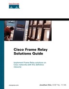
In addition to adaptive shaping to BECN, Frame Relay Traffic Shaping supports adaptive shaping to ForeSight, an additional functionality that allows a Cisco router to actively communicate with a Cisco Frame Relay switch using timed ForeSight messages. When adaptive shaping to ForeSight is enabled, a Cisco router can dynamically adjust its transmission rate based on congestion conditions reported in ForeSight messages received from the switch without relying on remote devices to send BECN tagged packets. Figure 5-1 illustrates the small difference between adaptive shaping to BECN and ForeSight.
In summary, the Frame Relay Traffic Shaping feature provides functionalities in three major components:
This section discusses how Frame Relay Traffic Shaping generally works. Figure 5-2 illustrates a flow diagram of a packet arriving on an interface of a router that has Frame Relay Traffic Shaping enabled on the packet's outgoing interface.
An incoming packet that enters an interface of a router can be fast switched or process switched.
Process switching is a “process-oriented” switching method that requires a routing table lookup for every packet switched. With process switching, the router copies an incoming packet to the processor memory, consults its Layer 3 routing table to determine the next hop address and output interface, and finally rewrites the packet with the destination address and frame Media Access Control (MAC) header. Process switching is slow, but it supports per-packet load-sharing.
Fast switching is a major improvement over process switching. In fast switching, a route cache is used to speed up the entire switching process. With fast switching, when an incoming packet is received by a router on an interface, the router performs a lookup in its route cache for the destination network address. If there is an entry in the route cache, the router immediately rewrites the header and forwards the packet to the corresponding output interface. If a route cache entry does not exist for the destination of the packet, the packet is process switched, but an entry is populated in the route cache. Subsequent packets received by the router that are destined for the same destination are fast switched as long as the cache entry exists.
Fast switching is enabled by default on all interfaces that support fast switching. Fast switching only supports per-destination-based load-sharing.
If the transit packet needs to exit on an interface of the router that does not have Frame Relay Traffic Shaping enabled, the packet is immediately sent the output interface. However, if the router needs to transmit a packet on an interface that has Frame Relay Traffic Shaping enabled, the router needs to verify several things. First, the router checks whether sufficient credit is available to transmit the packet. The term credit is analogous to a measure of available bandwidth that can be used without causing oversubscription on the network. The credit system used in Frame Relay Traffic Shaping is based on a token bucket algorithm, which is explained later in this section.
If there is sufficient credit available, the router immediately sends the packet to the output interface, deducts the packet size from the credit pool, and then proceeds to start the transmission process for the packet. On the other hand, if there is insufficient credit available, the packet has to be delayed and is immediately sent to a queue set up on the outgoing Frame Relay permanent virtual circuit (PVC). The packet is held in the queue and waits until sufficient credits have built up for transmission. However, in the event the queue on the Frame Relay PVC is full, the router discards the packet. The Frame Relay Traffic Shaping feature supports several queuing systems on a Frame Relay PVC. The queuing algorithms include the default FIFO queuing, priority queuing, and custom queuing.
NOTE
Each queuing system supports different a queue size or depth. By default, the queue depth of FIFO queues is 40 packets. The user specifies the queue depths of priority queues and custom queues.
The Frame Relay Traffic Shaping feature uses a credit system based on a leaky bucket algorithm to regulate traffic flows. The following section provides the definition of the leaky bucket algorithm and explains how it works. The flow diagram of the token bucket algorithm is shown in Figure 5-3.

A token bucket is a mechanism that rate enforcement systems use to define the rate of transfer and to regulate the flow of traffic entering a network. Frame Relay Traffic Shaping implements a variation of the token bucket algorithm also known as the leaky bucket algorithm. The leaky bucket algorithm smooths out the data flow exiting the traffic shaper and entering the Frame Relay network. In the context of this chapter, the terms “token bucket” and “leaky bucket” are used interchangeably. In the token bucket algorithm system, the token bucket has a fixed size and contains tokens that are typically equal in representation to actual packet size.
Beginning with the Credit available condition in the flow chart diagram depicted in Figure 5-3, the Frame Relay Traffic Shaping system transmits a packet from a queue only if there are available tokens equivalent to the size of the packet in the token bucket. If sufficient tokens are available, the packet is sent to the output interface for transmission, and the required tokens are removed from the token bucket.
After the transmission of the packet is completed, the system verifies whether the Frame Relay PVC queues are empty. If the queues are not empty (which indicates congestion), the system smooths the output rate. This prevents overrun by ensuring that the next packet is transmitted after a time interval when tokens are replenished. If there is no congestion (as indicated by an empty queue), the arriving packet is transmitted, and the tokens are removed from the token bucket. If there are not enough tokens in the bucket, the arriving packet is sent to the queues, or the system continues to buffer the existing packets in the queues until sufficient tokens are available in the next time interval. In the event that there are no available tokens and the queues on the Frame Relay PVC are filled, the arriving packets are discarded.
In every time interval, the token bucket system generates tokens, and the tokens are added to the token bucket. The time interval is a constant fixed rate, which is also known as the measurement interval. If the token bucket is full when tokens are replenished, the newly arriving tokens are discarded instead of overflowing the token bucket.
The token bucket algorithm uses several important parameters: mean rate, burst size, and time interval. They are related by the following formula:
mean rate = burst size / time interval
Consider the Frame Relay terminologies introduced in Chapter 1, “Introduction to Frame Relay.” In Frame Relay terms, the mean rate defined in the token bucket algorithm is equal to the CIR, which is defined as the rate of transfer in bits per second that the network commits to transfer under normal conditions. The burst size corresponds to the committed burst (Bc). It represents the maximum amount of committed data that may be sent in one time interval Tc. The excess burst (Be) is the maximum amount of uncommitted data that may be sent in one time interval Tc.
The leaky bucket that Frame Relay Traffic Shaping uses has a maximum capacity of Bc plus Be. Hence, the maximum burst allowed is equal to Bc + Be. A sum of tokens equivalent to Bc is added to the token bucket in every Tc time interval. When the router needs to transmit a packet on an exit interface with Frame Relay Traffic Shaping enabled, the packet is transmitted only if there are sufficient tokens in the token bucket. Otherwise, the packet is buffered in the queues set up on the Frame Relay PVC until sufficient tokens are available. In this way, Frame Relay Traffic Shaping ensures that the long-term transmission rate does not exceed the established rate at which tokens are replaced in the bucket and allows the network to manage congestion.
This section discusses the adaptive shaping to BECN component of the Frame Relay Traffic Shaping feature. When adaptive shaping to BECN is enabled on a Cisco router, the router throttles its output transmission rate on a Frame Relay PVC based on BECN tagged packets received from the Frame Relay network. To use adaptive shaping to BECN, Frame Relay Traffic Shaping must be configured at the main interface.
When a Cisco router receives a BECN tagged packet in the opposite direction of an active traffic flow, this represents a signal of congestion in the Frame Relay network. The router responds to this condition by decreasing its output transmission rate on the congested Frame Relay PVC by a large amount. Subsequently, the router continues to lower its output rate on the Frame Relay PVC with every BECN tagged packet received until its present transmission rate eventually drops to the Minimum CIR (MINCIR) value. The router should not lower its transmission rate to a level below the true CIR rate guaranteed by the service provider.
After a period of time when the router no longer receives any BECN tagged packets, the router increases and builds up the transmission rate slightly to avoid any underutilization. Note that because adaptive shaping to BECN depends on a BECN tagged packet being received from the congested network, it requires a user packet with the BECN tagged frame to be sent in the opposite direction of the active traffic flow causing congestion.
When setting up the parameters for adaptive shaping to BECN, the MINCIR value on the router is normally set to the true CIR value of the Frame Relay PVC purchased from the service provider. To allow oversubscription, the CIR value on the router is set to the physical link access rate.
Adaptive shaping to ForeSight allows a Cisco router to respond to ForeSight messages and to react to network congestion by enabling VC-level traffic shaping and rate limiting in a timely manner. Adaptive shaping to ForeSight is a component of Frame Relay Traffic Shaping. On Cisco switches, router ForeSight is a network traffic control software that allows the Frame Relay switches to extend ForeSight messages over a User-to-Network (UNI) interface and passes the BECN bit for VCs.
To enable adaptive shaping to ForeSight on a Cisco router, Frame Relay Traffic Shaping must be configured on the main interface. Additionally, the Frame Relay switch must be able to support adaptive shaping to ForeSight.
NOTE
By default, adaptive shaping to ForeSight is enabled on a Cisco router when Frame Relay Traffic Shaping is configured. However, it is not applied to any VC until the frame-relay adaptive-shaping foresight command is applied to the specified VC's map class.
When adaptive shaping to ForeSight is configured on a Frame Relay switch, the switch periodically sends out ForeSight messages based on a configured time interval (which ranges from 40 to 5000 milliseconds). On receiving ForeSight messages that carry congestion information from the switch, the router becomes aware that certain data-link connection identifiers (DLCIs) are congested. The router responds to the ForeSight message by applying traffic shaping to slow down the output rate on the congested VCs.
Compared with adaptive shaping to BECN, the router reacts in the same way as if it had received a BECN tagged packet. Therefore, both adaptive shaping to BECN and ForeSight reduce the output traffic rate during periods of network congestion. A notable difference between BECN and ForeSight is that BECN requires a user packet to be sent in the direction of the congested DLCI to inform a congested state. However, sending user packets is unpredictable and thus is generally not a reliable mechanism. On the other hand, timed ForeSight messages allow a router to always receive a congestion notification message before congestion escalates to become a significant problem. With adaptive shaping to ForeSight, traffic shaping is applied timely to slow down the output traffic rate on the congested DLCIs.
Frame Relay Traffic Shaping is available as of IOS Software Release 11.2 with adaptive shaping to BECN support. In Cisco IOS Software Release 11.3, adaptive shaping to ForeSight message support has been added to the traffic shaping feature's list of functionalities.
This section discusses the IOS configuration commands for configuring Frame Relay Traffic Shaping on a Cisco router.
NOTE
For this discussion, IOS Release 12.2(1) was used on all routers in the lab to maintain a consistency of software versions. The same release was used in the case study scenarios at the end of this chapter.
Before configuring Frame Relay Traffic Shaping on a Cisco router, you must enable Frame Relay encapsulation on the main interface. By default, configuring Frame Relay Traffic Shaping on the main interface enables traffic shaping with per-VC queuing for all PVCs and switched virtual circuits (SVCs) under the main interface. To configure Frame Relay Traffic Shaping on a specified main interface, follow the configuration steps listed below:
Go into the interface configuration mode of the main interface on which you want to configure Frame Relay Traffic Shaping. Frame Relay encapsulation must be enabled on the specified main interface.
Enable Frame Relay Traffic Shaping with per-VC queuing on the main interface with the frame-relay traffic-shaping interface configuration command.
Example 5-1 shows a configuration example of enabling Frame Relay Traffic Shaping on an interface.
Example 5-1. Configuration Example for Enabling Frame Relay Traffic Shaping
Router#configure terminal
Enter configuration commands, one per line.  End with CNTL/Z.
Router(config)#interface serial4/2
Router(config-if)#encapsulation frame-relay
Router(config-if)#frame-relay traffic-shaping
Router(config-if)#
A Frame Relay map-class command is used to define and set up the various traffic shaping parameters for use in the feature. The traffic rate enforcement parameters, per-VC queuing, and adaptive shaping to BECN or ForeSight are collectively configured under a Frame Relay map class. Table 5-1 summarizes the Frame Relay Traffic Shaping parameters that are used to manage traffic.
Table 5-1. Traffic Shaping Parameters
Parameters | Definitions |
|---|---|
Bc | Committed burst size |
Be | Excess burst size |
CIR | Committed information rate |
DE | Discard eligibility |
EIR | Excess information rate |
MINCIR | Minimum CIR, defaults to half the value of CIR |
Tc | Measurement interval, equal to Bc/CIR |
To configure a map class, follow the configuration steps listed as follows:
In the global configuration mode, specify the map class name with map-class frame-relay map-class-name. This enters the user into the map-class configuration mode.
(optional) In the map-class configuration mode, specify a custom queue list for the map class with the frame-relay custom-queue-list list-number command. This requires the user to create the custom queue list.
(optional) In the map-class configuration mode, specify a priority queue list for the map class with the frame-relay priority-group list-number command. This requires the user to create the priority queue group.
(optional) In the map-class configuration mode, set the following parameters for rate enforcement:
Specify the CIR with frame-relay cir bps command.
Specify the MINCIR with frame-relay mincir bps command.
Specify the committed burst size with frame-relay bc bits command.
Specify the excess burst size with frame-relay be bits command.
The single frame-relay traffic-rate CIR max-peak command can be used to set the CIR rate and the maximum peak (CIR + EIR).
Specify the idle timer with frame-relay idle-timer duration command. The command is usually used for SVC connections to specify the maximum idle time before tearing down the connection.
(optional) In the map-class configuration mode, enable BECN or ForeSight feedback on the map class with the frame-relay adaptive-shaping { becn | foresight } command.
Example 5-2 shows an example of creating a Frame Relay map class named QOS.
Example 5-2. Creating a Frame Relay Map Class
Router#configure terminal
Enter configuration commands, one per line.  End with CNTL/Z.
Router(config)#map-class frame-relay QOS
Router(config-map-class)#
Example 5-3 shows a configuration example of assigning a custom queue list to the QOS map class.
Example 5-3. Assigning a Custom Queue List to the Map Class
Router#configure terminal
Enter configuration commands, one per line.  End with CNTL/Z.
Router(config)#map-class frame-relay QOS
Router(config-map-class)#frame-relay custom-que
Router(config-map-class)#frame-relay custom-queue-list ?
  <1-16>  Custom queue list number

Router(config-map-class)#frame-relay custom-queue-list 1
Example 5-4 shows a configuration example of assigning a priority queue group to the QOS map class.
Example 5-4. Assigning a Priority Queue Group to the Map Class
Router#configure terminal
Enter configuration commands, one per line.  End with CNTL/Z.
Router(config)#map-class frame-relay QOS
Router(config-map-class)#frame-relay priority-group ?
  <1-16>  Priority group number

Router(config-map-class)#frame-relay priority-group 1
NOTE
Under a Frame Relay map class, only a single type of queuing can be configured at any one time. For example, if a custom queue list is applied to the map class, it is not possible to apply a priority group to the same map class without first removing the custom queue list. Moreover, if neither priority queuing nor custom queuing is configured, the Frame Relay map class defaults to FIFO queuing. The case studies later in this chapter provide some configuration examples of setting a priority group and a custom queue list using access lists.
Example 5-5 shows a configuration example setting up the various Frame Relay Traffic Shaping parameters inside a Frame Relay map class. The frame-relay cir command shown in this example specifies the inbound or outbound CIR. It is important to know that the CIR value specified in the map class usually does not reflect the CIR value given by the Frame Relay carriers. Most often, the CIR value specified in the frame-relay cir command represents the rate at which the Frame Relay access router sends its traffic on the VC into the Frame Relay network, averaged over a minimum increment of time (Tc). The “in” and “out” parameters for the frame-relay cir command are optional, but when the direction is not specified, the configured CIR is applied to both incoming and outgoing directions.
NOTE
When Frame Relay Traffic Shaping is enabled, and if a particular DLCI or VC has no map class applied under it, that DLCI or VC is assigned a default map class with a CIR value of 56000.
The frame-relay bc and frame-relay be map-class configuration commands set the committed burst size and the excess burst size, respectively. As a rule of thumb, Bc is usually set to 1/8 the value of CIR. Be represents the excess burst size.
The frame-relay mincir command sets the minimum acceptable level of CIR on the VC, either in the outgoing direction or both incoming and outgoing. When Frame Relay Traffic Shaping is used for an oversubscription configuration, the MINCIR value is typically set to the CIR value assigned by the Frame Relay carriers. The CIR value is then set to the link access speed. In this way, it is possible to burst above the guaranteed rate when there is no congestion and then to fall back to the guaranteed rate when congestion builds up.
Alternatively, the traffic shaping parameters can be set up using a single frame-relay traffic-rate map-class configuration command. The first parameter in the frame-relay traffic-rate command specifies the average rate (normally true CIR value) and the second parameter indicates the peak rate (CIR + EIR rate).
Take note that the units of measurement used in the Frame Relay map-class configuration commands for setting up the traffic shaping parameters is bits per second (bps).
Example 5-5. Configuration Example for Frame Relay Traffic Shaping Parameters Setup
Router(config-map-class)#frame-relay cir ?
  <1-45000000>  Applied to both Incoming/Outgoing CIR, Bits per second
  in            Incoming CIR
  out           Outgoing CIR

Router(config-map-class)#frame-relay cir 128000

Router(config-map-class)#frame-relay bc ?
  <300-16000000>  Applied to both Incoming/Outgoing Bc, Bits
  in              Incoming Bc
  out             Outgoing Bc
  <cr>

Router(config-map-class)#frame-relay bc 16000
Router(config-map-class)#frame-relay be ?
  <0-16000000>  Applied to both Incoming/Outgoing Be, Bits
  in            Incoming Be
  out           Outgoing Be
  <cr>

Router(config-map-class)#frame-relay be 0

Router(config-map-class)#frame-relay mincir ?
  <1000-45000000>  Applied to both Incoming/Outgoing CIR, Bits per second
  out              Outgoing minimum acceptable CIR

Router(config-map-class)#frame-relay mincir 64000

Router(config-map-class)#frame-relay traffic-rate ?
  <600-45000000>  Committed Information Rate (CIR)

Router(config-map-class)#frame-relay traffic-rate 64000 128000
NOTE
Typically, the “out” or default option is used in the commands for setting up the Frame Relay Traffic Shaping parameters in a map class.
Example 5-6 shows a configuration example of enabling BECN and ForeSight as the congestion backward notification mechanism for Frame Relay Traffic Shaping. This is accomplished with the frame-relay adaptive-shaping {BECN | ForeSight} configuration command under the Frame Relay map-class configuration mode. Both congestion notification mechanisms are mutually exclusive. For example, when adaptive shaping to BECN is enabled, configuring adaptive shaping to ForeSight in the same map class automatically removes adaptive shaping to BECN.
Example 5-6. Configuring Adaptive Shaping to BECN as the Selected Congestion Notification
Enter configuration commands, one per line.  End with CNTL/Z.
Router(config)#map-class frame-relay QOS
Router(config-map-class)#frame-relay adaptive-shaping becn
Router(config-map-class)#

Router#show running-config
Building configuration...

Current configuration : 2493 bytes
<output omitted>

map-class frame-relay QOS
 frame-relay traffic-rate 64000 128000
 frame-relay adaptive-shaping becn
 frame-relay cir 128000
 frame-relay bc 16000
 frame-relay be 0
 frame-relay mincir 64000
 frame-relay priority-group 1
Router#

Router#configure terminal
Enter configuration commands, one per line.  End with CNTL/Z.
Router(config)#map-class frame-relay QOS
Router(config-map-class)#frame-relay adaptive-shaping foresight
Router(config-map-class)#
Router#show running-config
Building configuration...
Current configuration : 2493 bytes

<output omitted>
!
map-class frame-relay QOS
 frame-relay traffic-rate 64000 128000
 frame-relay adaptive-shaping foresight
 frame-relay cir 128000
 frame-relay bc 16000
 frame-relay be 0
 frame-relay mincir 64000
 frame-relay priority-group 1
Router#
After setting up a Frame Relay map class with the default or user-defined traffic shaping parameters, the configured map class has to be associated with a main interface or a subinterface or assigned directly to a VC. For this purpose, the frame-relay class interface configuration command is used to associate a created Frame Relay map class with a specified main interface or subinterface.
A user can choose from three levels of a hierarchy when associating a Frame Relay map class. First of all, when a Frame Relay map class is associated with a main interface, the map class's configurations apply to all VCs under the main interface. All existing VCs on any subinterfaces created under the main interface inherit the traffic shaping parameters defined in the map class.
If a map class is applied at the subinterface level, all existing VCs under the chosen subinterface inherit the map class's traffic shaping configurations, but they override any map class associated with the main interface if there are any configured.
The final level of the hierarchy allows a map class to be directly associated with an individual VC at the per-DLCI level using the class virtual circuit configuration command. As such, the VC bypasses and overrides any map class applied at the main interface or subinterface. To illustrate this slightly perplexing concept, a simple configuration is used in Example 5-7.
Example 5-7. Associating a Frame Relay Map Class
Router#show running-config
<output omitted>
!
interface serial2/0
encapsulation frame-relay
frame-relay class class_a
interface serial2/0.1 multipoint
frame-relay class class_b
frame-relay interface-dlci 100
frame-relay interface-dlci 200
  class class_c
  !
map-class frame-relay class_a
!
map-class frame-relay class_b
!
map-class frame-relay class_c
In this configuration, DLCI 200 is associated directly with the map class class_c. Using the class configuration command at the DLCI level overrides map class class_a and class_b assigned to the main interface and subinterface, respectively. DLCI 100 under the subinterface s2/0.1 is associated with map-class class_b and overrides map class class_a. Finally, all VCs under the main interface not associated with any subinterface or VC level map classes are associated with the map class class_a.
To associate a Frame Relay map class to either a main interface or a subinterface, follow the configuration steps listed as follows, beginning in global configuration mode:
Go into the main interface or subinterface configuration mode of the main interface/subinterface on which you want to associate the Frame Relay map class.
Associate the map class to the main interface or subinterface with the frame-relay class class-name command. To remove the Frame Relay map class from the main interface or subinterface, use the no form the frame-relay class command.
Example 5-8 shows a configuration example associating the Frame Relay map class named fast_vc at the main interface and subinterface level.
Example 5-8. Configuration Example Associating Map Class at the Interface and Subinterface Level
Router#configure terminal
Enter configuration commands, one per line.  End with CNTL/Z.
Router(config)#interface serial3/0
Router(config-if)#frame-relay class ?
  WORD  map class name

Router(config-if)#frame-relay class fast_vc

Router#configure terminal
Enter configuration commands, one per line.  End with CNTL/Z.
Router(config)#interface serial3/0.1 multipoint
Router(config-subif)#frame-relay class ?
  WORD  map class name

Router(config-subif)#frame-relay class fast_vc
To associate a Frame Relay map class directly at the VC level, follow the configuration steps listed as follows, beginning in the interface or subinterface configuration mode:
Go into the Frame Relay DLCI configuration mode from the interface or subinterface mode with the frame-relay interface-dlci dlci command.
To associate a map class with a specified DLCI, use the class virtual circuit configuration command. To remove the association between the DLCI and the map class, use the no form of this command.
Example 5-9 presents configuration examples for associating a Frame Relay map class directly to a DLCI assigned to a multipoint subinterface.
Example 5-9. Configuration Examples for Associating a Specific Map Class Directly to a DLCI
Router#configure terminal
Enter configuration commands, one per line.  End with CNTL/Z.
Router(config)#interface serial3/0.1 multipoint
Router(config-subif)#frame-relay interface-dlci 100
Router(config-fr-dlci)#class ?
  WORD  map class name

Router(config-fr-dlci)#class slow_vc
This section uses a hub-and-spoke Frame Relay network to illustrate the Cisco IOS show commands, which are useful for monitoring Frame Relay Traffic Shaping information on a Cisco router. The hub-and-spoke Frame Relay network is depicted in Figure 5-4.
In this setup, a hub-and-spoke Frame Relay network with a central hub site is connected to three remote branch office sites. The central hub site is connected to two remote branch office sites with a multipoint subinterface residing on subnet 172.16.1.0/24. The central hub site is connected to the third remote branch office site on a point-to-point link residing on subnet 172.16.2.0/30. At the same time, a few servers are set up to generate network traffic from the central hub site into the Frame Relay network.
The main objective of the traffic simulation is to analyze the traffic shaping functions on the routers based on the parameters defined in the routers' configurations. Frame Relay Traffic Shaping is enabled on all the routers in the network. In this example, the routers are connected directly to a Cisco IGX 8420 multiservice WAN switch configured as a Frame Relay switch. On the Frame Relay switch, three Frame Relay PVCs are provisioned to carry traffic between the sites. The point-to-point Frame Relay PVC between hub router A and remote spoke router D is provisioned with an end-to-end CIR of 64 kpbs. The Frame Relay PVCs on hub router A connected to spoke router B and spoke router C each has a lower CIR rate of 32 kpbs.
Example 5-10 shows the running configuration of the routers based on the parameters defined in Figure 5-4.
Example 5-10. Running Configurations of the Routers
! RouterA Configuration:

   RouterA#show running-config
   Building configuration...
   <output-omitted>
   !
   interface Ethernet1/1
    ip address 192.168.1.254 255.255.255.0
   !
   interface Serial3/0
    bandwidth 128
    no ip address
    encapsulation frame-relay
    frame-relay class slow_vc
    frame-relay traffic-shaping
   !
   interface Serial3/0.101 multipoint
    ip address 172.16.1.1 255.255.255.0
    frame-relay map ip 172.16.1.2 102 broadcast
    frame-relay map ip 172.16.1.3 103 broadcast
   !
   interface Serial3/0.104 point-to-point
    ip address 172.16.2.1 255.255.255.252
    frame-relay interface-dlci 104
     class fast_vc
   !
   map-class frame-relay fast_vc
    frame-relay cir 64000
    frame-relay bc 8000
    frame-relay be 0
   !
   map-class frame-relay slow_vc
    frame-relay cir 32000
    frame-relay bc 4000
    frame-relay be 0

   ! Router B Configuration:

   RouterB#show running-config
   Building configuration...
   <output omitted>
   !
   interface Serial1/1
    ip address 172.16.1.2 255.255.255.0
    encapsulation frame-relay
    frame-relay class slow-vc
    frame-relay traffic-shaping
    frame-relay map ip 172.16.1.1 201 broadcast
    frame-relay map ip 172.16.1.3 201 broadcast
   !
   map-class frame-relay slow-vc
    frame-relay cir 32000
    frame-relay bc 4000
    frame-relay be 0

   ! Router C Configuration:

   RouterC#show running-config
   Building configuration...
   <output omitted>
   !
   interface Serial3
    ip address 172.16.1.3 255.255.255.0
    encapsulation frame-relay
    frame-relay class slow-vc
    frame-relay traffic-shaping
    frame-relay map ip 172.16.1.1 301 broadcast
    frame-relay map ip 172.16.1.2 301 broadcast
   !
   map-class frame-relay slow-vc
    frame-relay cir 32000
    frame-relay bc 4000
    frame-relay be 0

   ! Router D Configuration:

   RouterD#show running-config
   Building configuration...
   <output omitted>
   !
   interface Serial0
    no ip address
    encapsulation frame-relay
    frame-relay traffic-shaping
   !
   interface Serial0.401 point-to-point
    ip address 172.16.2.2 255.255.255.252
    frame-relay interface-dlci 401
     class fast-vc
   !
   map-class frame-relay fast-vc
    frame-relay cir 64000
    frame-relay bc 8000
    frame-relay be 0
The show frame-relay pvc [dlci] command in the privileged EXEC mode displays the statistics of a Frame Relay PVC referenced by its DLCI on a Cisco router. The dlci parameter is optional. If it is not supplied, the show frame-relay pvc command displays the information of all Frame Relay PVCs created on the router. Alternatively, there is a full version of the command that involves supplying the DLCI value of a particular Frame Relay PVC. The show frame-relay pvc dlci command displays more detailed information on the selected PVC. The additional information shown includes the CIR, Bc, Be, and MINCIR values; the status of shaping; the number of packets dropped by shaping; and the queuing strategy used. Example 5-11 illustrates the output of both versions of the show frame-relay pvc command executed on the routers in Figure 5-4.
Example 5-11. Sample Output of show frame-relay pvc Command at the Hub Router
RouterA#show frame-relay pvc

PVC Statistics for interface Serial3/0 (Frame Relay DTE)

              Active     Inactive      Deleted       Static
  Local          3            0            0            0
  Switched       0            0            0            0
  Unused         0            0            0            0

DLCI = 102, DLCI USAGE = LOCAL, PVC STATUS = ACTIVE, INTERFACE = Serial3/0.102

  input pkts 0             output pkts 0            in bytes 0
  out bytes 0              dropped pkts 0           in pkts dropped 0
  out pkts dropped 0                out bytes dropped 0
  in FECN pkts 0           in BECN pkts 0           out FECN pkts 0
  out BECN pkts 0          in DE pkts 0             out DE pkts 0
  out bcast pkts 0         out bcast bytes 0
  5 minute input rate 0 bits/sec, 0 packets/sec
  5 minute output rate 0 bits/sec, 0 packets/sec
pvc create time 00:43:22, last time pvc status changed 00:43:02

DLCI = 103, DLCI USAGE = LOCAL, PVC STATUS = ACTIVE, INTERFACE = Serial3/0.102
  input pkts 0             output pkts 0            in bytes 0
  out bytes 0              dropped pkts 0           in pkts dropped 0
  out pkts dropped 0                out bytes dropped 0
  in FECN pkts 0           in BECN pkts 0           out FECN pkts 0
  out BECN pkts 0          in DE pkts 0             out DE pkts 0
  out bcast pkts 0         out bcast bytes 0
  5 minute input rate 0 bits/sec, 0 packets/sec
  5 minute output rate 0 bits/sec, 0 packets/sec
pvc create time 00:43:32, last time pvc status changed 00:43:12

DLCI = 104, DLCI USAGE = LOCAL, PVC STATUS = ACTIVE, INTERFACE = Serial3/0.104

  input pkts 0             output pkts 1            in bytes 0
  out bytes 298            dropped pkts 0           in pkts dropped 0
  out pkts dropped 0                out bytes dropped 0
  in FECN pkts 0           in BECN pkts 0           out FECN pkts 0
  out BECN pkts 0          in DE pkts 0             out DE pkts 0
  out bcast pkts 0         out bcast bytes 0
  5 minute input rate 0 bits/sec, 0 packets/sec
  5 minute output rate 0 bits/sec, 0 packets/sec
pvc create time 00:43:48, last time pvc status changed 00:41:58

RouterA#show frame-relay pvc 102

PVC Statistics for interface Serial3/0 (Frame Relay DTE)

DLCI = 102, DLCI USAGE = LOCAL, PVC STATUS = ACTIVE, INTERFACE = Serial3/0.102

  input pkts 0             output pkts 0            in bytes 0
  out bytes 0              dropped pkts 0           in pkts dropped 0
  out pkts dropped 0       out bytes dropped 0
  in FECN pkts 0           in BECN pkts 0           out FECN pkts 0
  out BECN pkts 0          in DE pkts 0             out DE pkts 0
  out bcast pkts 0         out bcast bytes 0
  5 minute input rate 0 bits/sec, 0 packets/sec
  5 minute output rate 0 bits/sec, 0 packets/sec
  pvc create time 00:45:47, last time pvc status changed 00:45:27
  cir 32000     bc 4000      be 0         byte limit 500    interval 125
mincir 16000     byte increment 500   Adaptive Shaping none
  pkts 0         bytes 0         pkts delayed 0         bytes delayed 0
  shaping inactive
  traffic shaping drops 0
  Queueing strategy: fifo
Output queue 0/40, 0 drop, 0 dequeued

RouterA#show frame-relay pvc 103

PVC Statistics for interface Serial3/0 (Frame Relay DTE)

DLCI = 103, DLCI USAGE = LOCAL, PVC STATUS = ACTIVE, INTERFACE = Serial3/0.102

  input pkts 0             output pkts 0            in bytes 0
  out bytes 0              dropped pkts 0           in pkts dropped 0
  out pkts dropped 0       out bytes dropped 0
  in FECN pkts 0           in BECN pkts 0           out FECN pkts 0
  out BECN pkts 0          in DE pkts 0             out DE pkts 0
  out bcast pkts 0         out bcast bytes 0
  5 minute input rate 0 bits/sec, 0 packets/sec
  5 minute output rate 0 bits/sec, 0 packets/sec
  pvc create time 00:45:50, last time pvc status changed 00:45:30
  cir 32000     bc 4000      be 0         byte limit 500    interval 125
  mincir 16000     byte increment 500   Adaptive Shaping none
  pkts 0         bytes 0         pkts delayed 0         bytes delayed 0
  shaping inactive
  traffic shaping drops 0
  Queueing strategy: fifo
Output queue 0/40, 0 drop, 0 dequeued

RouterA #show frame-relay pvc 104

PVC Statistics for interface Serial3/0 (Frame Relay DTE)

DLCI = 104, DLCI USAGE = LOCAL, PVC STATUS = ACTIVE, INTERFACE = Serial3/0.104

  input pkts 3             output pkts 3            in bytes 891
  out bytes 894            dropped pkts 0           in pkts dropped 0
  out pkts dropped 0                out bytes dropped 0
  in FECN pkts 0           in BECN pkts 0           out FECN pkts 0
  out BECN pkts 0          in DE pkts 0             out DE pkts 0
  out bcast pkts 3         out bcast bytes 894
  5 minute input rate 0 bits/sec, 0 packets/sec
  5 minute output rate 0 bits/sec, 0 packets/sec
  pvc create time 00:45:52, last time pvc status changed 00:44:02
  cir 64000     bc 8000      be 0         byte limit 1000   interval 125
  mincir 32000     byte increment 1000  Adaptive Shaping none
  pkts 3         bytes 894       pkts delayed 0         bytes delayed 0
  shaping inactive
  traffic shaping drops 0
  Queueing strategy: fifo
Output queue 0/40, 0 drop, 0 dequeued
The show traffic-shape command in the user EXEC mode can be used to display interface-by-interface information of the traffic shaping rate configurations on the router. Refer to Example 5-12 for a sample output of this command, executed on router A in Figure 5-4.
Example 5-12. The show traffic-rate Command
RouterA#show traffic-shape

Interface   Se3/0.102
       Access Target    Byte   Sustain   Excess    Interval  Increment Adapt
VC     List   Rate      Limit  bits/int  bits/int  (ms)      (bytes)   Active
103           32000     500    4000      0         125       500       -
102           32000     500    4000      0         125       500       -

Interface   Se3/0.104
       Access Target    Byte   Sustain   Excess    Interval  Increment Adapt
VC     List   Rate      Limit  bits/int  bits/int  (ms)      (bytes)   Active
104           64000     1000   8000      0         125       1000      -
Figure 5-5 provides an explanation of the various fields that the show traffic-rate command displays.
Given the Frame Relay network setup in Figure 5-4 and the routers' configurations in Example 5-10, traffic streams are set up on the servers residing on the 192.168.1.0/24 subnet. The main objective in this section is to generate downstream traffic from the servers toward the spoke networks. Sufficient output traffic must be generated from the hub router entering the Frame Relay network to activate Frame Relay Traffic Shaping on the hub router.
Three individual traffic streams are set up on the servers with an initial rate of 24 kbps, 24 kbps, and 56 kbps. They are destined for router B, router C, and router D, respectively. On the hub router, recall that DLCI 102 and 103 have a CIR of 32 kbps each, and DLCI 104 has a CIR of 64 kbps. The traffic rate originating from the servers is stepped up to eventually cause congestion in the Frame Relay network and to activate Frame Relay Traffic Shaping on router A. The show frame-relay pvc dlci command is used to observe Frame Relay Traffic Shaping on the hub router A. Example 5-13 shows the output of the show frame-relay pvc command on router A before the traffic rate exceeds the traffic shaping threshold.
Example 5-13. Output of the show frame-relay pvc dlci Command After Traffic Ison, but Before Traffic Rate Reaches Shaping Threshold
RouterA#show frame-relay pvc 102

PVC Statistics for interface Serial3/0 (Frame Relay DTE)

DLCI = 102, DLCI USAGE = LOCAL, PVC STATUS = ACTIVE, INTERFACE = Serial3/0.102

  input pkts 0             output pkts 932          in bytes 0
  out bytes 932000         dropped pkts 0           in pkts dropped 0
  out pkts dropped 0                out bytes dropped 0
  in FECN pkts 0           in BECN pkts 0           out FECN pkts 0
  out BECN pkts 0          in DE pkts 0             out DE pkts 0
  out bcast pkts 0         out bcast bytes 0
  5 minute input rate 0 bits/sec, 0 packets/sec
  5 minute output rate 24000 bits/sec, 3 packets/sec
  pvc create time 01:10:51, last time pvc status changed 01:10:31
  cir 32000     bc 4000      be 0         byte limit 500    interval 125
  mincir 16000     byte increment 500   Adaptive Shaping none
  pkts 934       bytes 934000    pkts delayed 0         bytes delayed 0
  shaping inactive
  traffic shaping drops 0
  Queueing strategy: fifo
  Output queue 0/40, 0 drop, 5 dequeued

RouterA#show frame-relay pvc 103

PVC Statistics for interface Serial3/0 (Frame Relay DTE)

DLCI = 103, DLCI USAGE = LOCAL, PVC STATUS = ACTIVE, INTERFACE = Serial3/0.102

  input pkts 0             output pkts 1004         in bytes 0
  out bytes 1004000        dropped pkts 0           in pkts dropped 0
  out pkts dropped 0                out bytes dropped 0
  in FECN pkts 0           in BECN pkts 0           out FECN pkts 0
  out BECN pkts 0          in DE pkts 0             out DE pkts 0
  out bcast pkts 0         out bcast bytes 0
  5 minute input rate 0 bits/sec, 0 packets/sec
  5 minute output rate 24000 bits/sec, 3 packets/sec
  pvc create time 01:11:15, last time pvc status changed 01:10:55
  cir 32000     bc 4000      be 0         byte limit 500    interval 125
  mincir 16000     byte increment 500   Adaptive Shaping none
  pkts 1006      bytes 1006000   pkts delayed 0         bytes delayed 0
  shaping inactive
  traffic shaping drops 0
  Queueing strategy: fifo
Output queue 0/40, 0 drop, 0 dequeued

RouterA#show frame-relay pvc 104
PVC Statistics for interface Serial3/0 (Frame Relay DTE)

DLCI = 104, DLCI USAGE = LOCAL, PVC STATUS = ACTIVE, INTERFACE = Serial3/0.104

  input pkts 28            output pkts 2482         in bytes 8316
  out bytes 2462344        dropped pkts 0           in pkts dropped 0
  out pkts dropped 0                out bytes dropped 0
  in FECN pkts 0           in BECN pkts 0           out FECN pkts 0
  out BECN pkts 0          in DE pkts 0             out DE pkts 0
  out bcast pkts 28        out bcast bytes 8344
  5 minute input rate 0 bits/sec, 0 packets/sec
  5 minute output rate 56000 bits/sec, 7 packets/sec
  pvc create time 01:11:31, last time pvc status changed 01:09:41
  cir 64000     bc 8000      be 0         byte limit 1000   interval 125
  mincir 32000     byte increment 1000  Adaptive Shaping none
  pkts 2483      bytes 2463344   pkts delayed 5         bytes delayed 1490
  shaping inactive
  traffic shaping drops 0
  Queueing strategy: fifo
  Output queue 0/40, 0 drop, 5 dequeued
As seen in Example 5-13, the rate of the initial traffic streams is not sufficient to create congestion to activate Frame Relay Traffic Shaping on router A. To simulate congestion, the rate of the traffic streams originating from the servers has been increased dramatically to 40 kbps, 40 kbps, and 72 kbps (the aggregate output rate is 152 kbps). Example 5-14 shows the output of the show frame-relay pvc command on router A after the rate of the traffic streams has exceeded the traffic shaping thresholds.
Example 5-14. Output of the show frame-relay pvc dlci Command After Traffic Is on but Traffic Rate Has Exceeded Shaping Threshold
RouterA#show frame-relay pvc 102
PVC Statistics for interface Serial3/0 (Frame Relay DTE)

DLCI = 102, DLCI USAGE = LOCAL, PVC STATUS = ACTIVE, INTERFACE = Serial3/0.102

  input pkts 0             output pkts 2762         in bytes 0
  out bytes 2762000        dropped pkts 108         in pkts dropped 0
  out pkts dropped 108              out bytes dropped 108000
  late-dropped out pkts 108         late-dropped out bytes 108000
  in FECN pkts 0           in BECN pkts 0           out FECN pkts 0
  out BECN pkts 0          in DE pkts 0             out DE pkts 0
  out bcast pkts 0         out bcast bytes 0
  5 minute input rate 0 bits/sec, 0 packets/sec
  5 minute output rate 32000 bits/sec, 4 packets/sec
  pvc create time 01:20:07, last time pvc status changed 01:19:47
  cir 32000     bc 4000      be 0         byte limit 500    interval 125
  mincir 16000     byte increment 500   Adaptive Shaping none
  pkts 2725      bytes 2725000   pkts delayed 590       bytes delayed 590000
  shaping active
  traffic shaping drops 0
  Queueing strategy: fifo
  Output queue 40/40, 109 drop, 594 dequeued

RouterA#show frame-relay pvc 103
PVC Statistics for interface Serial3/0 (Frame Relay DTE)

DLCI = 103, DLCI USAGE = LOCAL, PVC STATUS = ACTIVE, INTERFACE = Serial3/0.102

  input pkts 0             output pkts 2901         in bytes 0
  out bytes 2901000        dropped pkts 144         in pkts dropped 0
  out pkts dropped 144              out bytes dropped 144000
  late-dropped out pkts 144         late-dropped out bytes 144000
  in FECN pkts 0           in BECN pkts 0           out FECN pkts 0
  out BECN pkts 0          in DE pkts 0             out DE pkts 0
  out bcast pkts 0         out bcast bytes 0
  5 minute input rate 0 bits/sec, 0 packets/sec
  5 minute output rate 32000 bits/sec, 4 packets/sec
  pvc create time 01:20:43, last time pvc status changed 01:20:23
  cir 32000     bc 4000      be 0         byte limit 500    interval 125
  mincir 16000     byte increment 500   Adaptive Shaping none
  pkts 2867      bytes 2867000   pkts delayed 732       bytes delayed 732000
  shaping active
  traffic shaping drops 0
  Queueing strategy: fifo
Output queue 39/40, 145 drop, 736 dequeued
RouterA#show frame-relay pvc 104
PVC Statistics for interface Serial3/0 (Frame Relay DTE)

DLCI = 104, DLCI USAGE = LOCAL, PVC STATUS = ACTIVE, INTERFACE = Serial3/0.104

  input pkts 38            output pkts 6674         in bytes 11286
  out bytes 6647324        dropped pkts 164         in pkts dropped 0
  out pkts dropped 164              out bytes dropped 164000
  late-dropped out pkts 164         late-dropped out bytes 164000
  in FECN pkts 0           in BECN pkts 0           out FECN pkts 0
  out BECN pkts 0          in DE pkts 0             out DE pkts 0
  out bcast pkts 38        out bcast bytes 11324
  5 minute input rate 0 bits/sec, 0 packets/sec
  5 minute output rate 64000 bits/sec, 8 packets/sec
  pvc create time 01:21:03, last time pvc status changed 01:19:13
  cir 64000     bc 8000      be 0         byte limit 1000   interval 125
  mincir 32000     byte increment 1000  Adaptive Shaping none
  pkts 6642      bytes 6615324   pkts delayed 1639      bytes delayed 1628470
  shaping active
  traffic shaping drops 0
  Queueing strategy: fifo
Output queue 40/40, 166 drop, 1647 dequeued
Frame Relay Traffic Shaping is activated on a Frame Relay PVC when the rate of the traffic flow it carries exceeds the traffic shaping threshold configured for the DLCI. As shown in router A's show frame-relay pvc output in Example 5-14, Frame Relay Traffic Shaping is active on DLCI 102, 103, and 104 due to congestion. The active shaper has rate limited the output traffic rate on DLCI 102, 103, and 104 to 32 kbps, 32 kbps, and 64 kbps, respectively. In addition, the default FIFO queue on each DLCI is full, and incoming frames are dropped. Frame Relay Traffic Shaping supports other queuing strategies, such as custom queuing and priority queuing, which are discussed in depth in Part IV of this book. Finally, the effective aggregate output rate at the physical interface is smoothed at 128 kbps, as shown in Example 5-15.
Example 5-15. The Aggregate Output Rate at the Interface Level on Router A
RouterA#show interface s3/0
Serial3/0 is up, line protocol is up
  Hardware is M4T
  MTU 1500 bytes, BW 1544 Kbit, DLY 20000 usec,
     reliability 255/255, txload 21/255, rxload 1/255
  Encapsulation FRAME-RELAY, crc 16, loopback not set
  Keepalive set (10 sec)
  Restart-Delay is 0 secs
  LMI enq sent  816, LMI stat recvd 816, LMI upd recvd 0, DTE LMI up
  LMI enq recvd 0, LMI stat sent  0, LMI upd sent  0
  LMI DLCI 1023  LMI type is CISCO  frame relay DTE
  FR SVC disabled, LAPF state down
  Broadcast queue 0/64, broadcasts sent/dropped 136/0, interface broadcasts 0
  Last input 00:00:03, output 00:00:00, output hang never
  Last clearing of "show interface" counters 02:16:01
  Input queue: 0/75/0/0 (size/max/drops/flushes); Total output drops: 18229
  Queueing strategy: fifo
  Output queue: 0/40 (size/max)
  5 minute input rate 0 bits/sec, 0 packets/sec
  5 minute output rate 128000 bits/sec, 16 packets/sec
     952 packets input, 54264 bytes, 0 no buffer
     Received 0 broadcasts, 0 runts, 0 giants, 0 throttles
     0 input errors, 0 CRC, 0 frame, 0 overrun, 0 ignored, 0 abort
     107834 packets output, 106933136 bytes, 0 underruns
     0 output errors, 0 collisions, 0 interface resets
     0 output buffer failures, 0 output buffers swapped out
     0 carrier transitions     DCD=up  DSR=up  DTR=up  RTS=up  CTS=up
The Frame Relay Traffic Shaping rate can be throttled dynamically by changing the configurations in the Frame Relay map class. This can be performed even when there is active traffic flowing in the router. Frame Relay Traffic Shaping can respond to the new parameters and adjust its shaper rate accordingly. The hub router A in Figure 5-4 activates Frame Relay Traffic Shaping on a DLCI to perform rate enforcement when the output traffic rate reaches the CIR threshold for the DLCI. Even after you increase the aggregate rate of the traffic streams originating from the server, the router continues to maintain its interface output rate at 128 kbps.
At this point, an example is used to verify how Frame Relay Traffic Shaping can dynamically throttle its output rate. The original CIR value in the Frame Relay map class fast_vc is changed while the router is still sending out traffic. In the fast_vc map class that is associated with DLCI 104, the CIR value in the map class is reduced from the initial 64 kpbs to 56 kpbs. Example 5-16 shows that Frame Relay Traffic Shaping has throttled the output rate on DLCI 104, resulting in more packets being delayed and dropped.
Example 5-16. After the CIR Is Reduced Dynamically
RouterA#configure terminal
Enter configuration commands, one per line.  End with CNTL/Z.
RouterA(config)#map-class frame-relay fast-vc
RouterA(config-map-class)#frame-relay cir 56000
RouterA#show frame-relay pvc 104

PVC Statistics for interface Serial3/0 (Frame Relay DTE)

DLCI = 104, DLCI USAGE = LOCAL, PVC STATUS = ACTIVE, INTERFACE = Serial3/0.104

  input pkts 151           output pkts 61227        in bytes 44847
  out bytes 61120998       dropped pkts 6971        in pkts dropped 0
  out pkts dropped 6971             out bytes dropped 6971000
  late-dropped out pkts 6971        late-dropped out bytes 6971000
  in FECN pkts 0           in BECN pkts 0           out FECN pkts 0
  out BECN pkts 0          in DE pkts 0             out DE pkts 0
  out bcast pkts 151       out bcast bytes 44998
  5 minute input rate 0 bits/sec, 0 packets/sec
  5 minute output rate 56000 bits/sec, 7 packets/sec
  pvc create time 03:14:27, last time pvc status changed 03:12:37
  cir 56000     bc 8000      be 0         byte limit 1000   interval 142
  mincir 28000     byte increment 994   Adaptive Shaping none
  pkts 61121     bytes 61014998  pkts delayed 56118     bytes delayed 56028144
  shaping active
  traffic shaping drops 0
  Queueing strategy: fifo
Output queue 40/40, 7043 drop, 56125 dequeued
This section describes how to verify that a Cisco router is able to regulate the output traffic rate according to the BECN or ForeSight congestion notifications. For the purpose of the verification, the Cisco IGX 8420 is now configured to manage network congestion using BECN flagged packets and timed ForeSight messages. The network diagram in Figure 5-4 has been modified slightly to look like the one shown in Figure 5-6.
An additional point-to-point VC (DLCI 501) is provisioned on the Frame Relay switch to connect between router A and router D. The hub router, router A, is configured to use adaptive shaping to BECN on DLCI 104 and adaptive shaping to ForeSight on DLCI 105, both under the same main interface. A server on router A's 199.0.0.0/24 subnet is set up to send a traffic stream to router A on each DLCI with an aggregate rate of 128 kbps. On the hub router A, the CIR in the Frame Relay map class is configured at 128 kbps, equivalent to the physical line speed of the access circuit connected to the Frame Relay switch. However, the true CIR provisioned on the Frame Relay switch for each PVC is 64 kpbs. Hence, the MINCIR value is configured at 64000 in the Frame Relay map-class setup for each VC. This arrangement mimics an oversubscription scenario where the switch allocates a bandwidth of 64 kbps to each VC, but the Frame Relay users send long bursts of data at a rate very close to the physical line speed. Example 5-17 shows the running configurations of Router A.
Example 5-17. Running Configurations for Router A
RouterA#show running-config
Building configuration...

Current configuration : 3420 bytes
<output omitted>
!
interface Ethernet1/2
 ip address 199.0.0.2 255.255.255.0
!
interface Serial6/1
 no ip address
 encapsulation frame-relay
 frame-relay traffic-shaping
!
interface Serial6/1.401 point-to-point
 ip address 192.168.1.1 255.255.255.252
 frame-relay interface-dlci 401
  class fast_vc_foresight
!
interface Serial6/1.501 point-to-point
 ip address 192.168.2.1 255.255.255.252
frame-relay interface-dlci 501
  class fast_vc_BECN
!
map-class frame-relay fast_vc_foresight
 frame-relay cir 128000
 frame-relay bc 16000
 frame-relay be 0
 frame-relay mincir 64000
 frame-relay adaptive-shaping foresight
!
map-class frame-relay fast_vc_BECN
 frame-relay cir 128000
 frame-relay bc 16000
 frame-relay be 0
 frame-relay mincir 64000
 frame-relay adaptive-shaping becn
Shortly after all traffic streams are sent out from the servers, the output rate at router A builds up rapidly. During a period of sustained congestion such the one introduced in this example, the router regulates its output traffic rate and discards any packets unable to be sent out or queued. With adaptive shaping to BECN or ForeSight enabled, a Cisco router dynamically reduces its output traffic rate by a large amount for every BECN tagged packet or timed ForeSight message received from the Frame Relay switch. The output rate falls substantially when adaptive shaping becomes active but the output rate does not drop below the configured MINCIR value (which is incidentally set to the true CIR value configured on the Frame Relay switch). After a time interval where the router detects no congestion (by not hearing it), the router starts to increase its output rate by a small increment. Example 5-18 shows the output of the following commands: show frame-relay pvc, show interface, and show traffic-shape at router A.
Example 5-18. Output of the Various show Commands
RouterA#show frame-relay pvc 401

PVC Statistics for interface Serial6/1 (Frame Relay DTE)

DLCI = 401, DLCI USAGE = LOCAL, PVC STATUS = ACTIVE, INTERFACE = Serial6/1.401

  input pkts 2138          output pkts 25249        in bytes 141127
  out bytes 25206155       dropped pkts 9581        in FECN pkts 0
  in BECN pkts 93          out FECN pkts 0          out BECN pkts 0
  in DE pkts 0             out DE pkts 0
  out bcast pkts 55        out bcast bytes 16635
  Shaping adapts to ForeSight        in ForeSight signals 606
  pvc create time 00:54:14, last time pvc status changed 00:08:14
  cir 128000    bc 16000     be 0         byte limit 2000   interval 125
  mincir 64000     byte increment 1125  Adaptive Shaping F/S
  pkts 15611     bytes 15568155  pkts delayed 15532     bytes delayed 15513904
  shaping active
  traffic shaping drops 0
  Queueing strategy: fifo
Output queue 40/40, 9598 drop, 15532 dequeued

RouterA#show frame-relay pvc 501

PVC Statistics for interface Serial6/1 (Frame Relay DTE)

DLCI = 501, DLCI USAGE = LOCAL, PVC STATUS = ACTIVE, INTERFACE = Serial6/1.501

  input pkts 2308          output pkts 10031        in bytes 151508
  out bytes 9991964        dropped pkts 3783        in FECN pkts 0
  in BECN pkts 278         out FECN pkts 0          out BECN pkts 0
  in DE pkts 0             out DE pkts 0
  out bcast pkts 56        out bcast bytes 16964
  Shaping adapts to BECN
  pvc create time 00:55:40, last time pvc status changed 00:09:40
  cir 128000    bc 16000     be 0         byte limit 2000   interval 125
  mincir 64000     byte increment 1375  Adaptive Shaping BECN
  pkts 6201      bytes 6161964   pkts delayed 6122      bytes delayed 6115040
  shaping active
  traffic shaping drops 0
  Queueing strategy: fifo
Output queue 40/40, 3790 drop, 6122 dequeued

RouterA#show traffic-shape

Interface   Se6/1.401
       Access Target    Byte   Sustain   Excess    Interval  Increment Adapt
VC     List   Rate      Limit  bits/int  bits/int  (ms)      (bytes)   Active
401           128000    2000   16000     0         125       1625      F/S

Interface   Se6/1.501
       Access Target    Byte   Sustain   Excess    Interval  Increment Adapt
VC     List   Rate      Limit  bits/int  bits/int  (ms)      (bytes)   Active
501           128000    2000   16000     0         125       1000      BECN
RouterA#

RouterA#show interface s6/1
Serial6/1 is up, line protocol is up
  Hardware is M4T
  MTU 1500 bytes, BW 2048 Kbit, DLY 20000 usec,
     reliability 255/255, txload 19/255, rxload 1/255
  Encapsulation FRAME-RELAY, crc 16, loopback not set
  Keepalive set (10 sec)
  LMI enq sent  762, LMI stat recvd 763, LMI upd recvd 0, DTE LMI up
  LMI enq recvd 0, LMI stat sent  0, LMI upd sent  0
  LMI DLCI 1023  LMI type is CISCO  frame relay DTE
  FR SVC disabled, LAPF state down
  Broadcast queue 0/64, broadcasts sent/dropped 256/4234, interface broadcasts 0
  Last input 00:00:00, output 00:00:00, output hang never
  Last clearing of "show interface" counters 02:07:11
  Queueing strategy: fifo
  Output queue 0/40, 32424 drops; input queue 0/75, 0 drops
  1 minute input rate 3000 bits/sec, 13 packets/sec
  1 minute output rate 157000 bits/sec, 20 packets/sec
     90330 packets input, 2286028 bytes, 0 no buffer
     Received 0 broadcasts, 0 runts, 0 giants, 0 throttles
     0 input errors, 0 CRC, 0 frame, 0 overrun, 0 ignored, 0 abort
     61070 packets output, 60123100 bytes, 0 underruns
     0 output errors, 0 collisions, 3 interface resets
     0 output buffer failures, 0 output buffers swapped out
     3 carrier transitions     DCD=up  DSR=up  DTR=up  RTS=up  CTS=up
The show interface command output (interface serial6/1) shown in the previous example indicates that the combined output traffic rate is now regulated at just about 156 kbps, dropped from the burst rate of 256 kbps (128 kbps x 2 DLCI). The aggregate CIR for both VCs on the line is 128 kbps. The controlled traffic rate is very close to the actual combined CIR allocated for both DLCIs on the Frame Relay switch. This verifies that both adaptive shaping to BECN and ForeSight are functioning properly when configured under the same main interface.
In Example 5-19, the traffic stream on DLCI 501 is turned off, and the output traffic rate on DLCI 401 is reduced to approximately 48 kbps, below the true CIR allocated on the Frame Relay switch. With this lower traffic rate, both Frame Relay Traffic Shaping and adaptive shaping to ForeSight are inactive.
Example 5-19. Frame Relay Traffic Shaping Is Inactive When Throughput Is Lower Than CIR
RouterA#show interface serial 6/1
Serial6/1 is up, line protocol is up
  Hardware is M4T
  MTU 1500 bytes, BW 2048 Kbit, DLY 20000 usec,
     reliability 255/255, txload 5/255, rxload 1/255
  Encapsulation FRAME-RELAY, crc 16, loopback not set
  Keepalive set (10 sec)
  LMI enq sent  1, LMI stat recvd 1, LMI upd recvd 0, DTE LMI up
  LMI enq recvd 0, LMI stat sent  0, LMI upd sent  0
  LMI DLCI 1023  LMI type is CISCO  frame relay DTE
  FR SVC disabled, LAPF state down
  Broadcast queue 0/64, broadcasts sent/dropped 0/0, interface broadcasts 0
  Last input 00:00:00, output 00:00:00, output hang never
  Last clearing of "show interface" counters 00:00:13
  Queueing strategy: fifo
  Output queue 0/40, 0 drops; input queue 0/75, 0 drops
  1 minute input rate 2000 bits/sec, 11 packets/sec
  1 minute output rate 48000 bits/sec, 6 packets/sec
     163 packets input, 4335 bytes, 0 no buffer
     Received 0 broadcasts, 0 runts, 0 giants, 0 throttles
     0 input errors, 0 CRC, 0 frame, 0 overrun, 0 ignored, 0 abort
     90 packets output, 88026 bytes, 0 underruns
     0 output errors, 0 collisions, 0 interface resets
     0 output buffer failures, 0 output buffers swapped out
     0 carrier transitions     DCD=up  DSR=up  DTR=up  RTS=up  CTS=up

RouterA#show frame-relay pvc 401

PVC Statistics for interface Serial6/1 (Frame Relay DTE)

DLCI = 401, DLCI USAGE = LOCAL, PVC STATUS = ACTIVE, INTERFACE = Serial6/1.401

  input pkts 116           output pkts 690          in bytes 7420
  out bytes 688608         dropped pkts 0           in FECN pkts 0
  in BECN pkts 0           out FECN pkts 0          out BECN pkts 0
  in DE pkts 0             out DE pkts 0
  out bcast pkts 2         out bcast bytes 608
  Shaping adapts to ForeSight        in ForeSight signals 0
  pvc create time 02:14:00, last time pvc status changed 00:04:00
  cir 128000    bc 16000     be 0         byte limit 2000   interval 125
  mincir 64000     byte increment 1000  Adaptive Shaping F/S
  pkts 690       bytes 688608    pkts delayed 0         bytes delayed 0
  shaping inactive
  traffic shaping drops 0
  Queueing strategy: fifo
  Output queue 0/40, 0 drop, 0 dequeued
When debugging adaptive shaping to ForeSight, you can use the debug frame-relay foresight debug command to monitor the received ForeSight messages on the router. This is shown in example 5-20.
Example 5-20. Using debug frame-relay foresight Command to Monitor Adaptive Shaping to ForeSight
Router#debug frame-relay foresight
02:39:50: FR rate control for DLCI 401 due to ForeSight msg
02:39:50: FR rate control for DLCI 401 due to ForeSight msg
02:39:50: FR rate control for DLCI 401 due to ForeSight msg
02:39:56: FR rate control for DLCI 401 due to ForeSight msg
02:40:02: FR rate control for DLCI 401 due to ForeSight msg
02:40:02: FR rate control for DLCI 401 due to ForeSight msg
02:40:08: FR rate control for DLCI 401 due to ForeSight msg
02:40:09: FR rate control for DLCI 401 due to ForeSight msg
The next section looks at several optional configuration commands for working with the Frame Relay Traffic Shaping feature.
The users can opt to specify which Frame Relay packets should have a lower priority or time sensitivity and should be subjected to be dropped when the Frame Relay switch experiences congestion. The Discard Eligibility (DE) mechanism allows the Frame Relay switch to identify packets that can be dropped during network congestion. This command assumes that the Frame Relay switch is able to detect and recognize the DE bit and to take action accordingly. Some Frame Relay switches are unable to interpret the DE bit and will do no action.
Use the frame-relay de-list global configuration command to define a DE list specifying the packets that have the DE bit set and thus are eligible for discarding when congestion is experienced on the Frame Relay switch.
Router(config)#frame-relay de-list list-number {protocol protocol | interface type number}characteristic
To delete a portion of a previously defined DE list, use the no form of this command. Table 5-2 lists the supported protocols and characteristics of the packet that can be used for classification.
Table 5-2. Syntax Description of frame-relay de-list Command
Syntax | Description |
|---|---|
Protocol | arp—. Address Resolution Protocol apollo—. Apollo Domain appletalk—. AppleTalk bridge—. bridging device clns—. ISO Connectionless Network Service clns_es—. CLNS end systems clns_is—. CLNS intermediate systems compressedtcp—. Compressed Transmission Control Protocol (TCP) decent—. DECnet decnet_node—. DECnet end node decnet_router-L1—. DECnet Level 1 (intraarea) router decnet_router-L2—. DECnet Level 2 (interarea) router ip—. Internet Protocol ipx—. Novell Internet Packet Exchange Protocol vines—. Banyan VINES xns—. Xerox Network Systems |
Characteristic | fragments—. Fragmented IP packets tcp port—. TCP packets to or from a specified port udp port—. User Datagram Protocol (UDP) packets to or from a specified port list access-list-number—. Previously defined access list number gt bytes—. Sets the DE bit for packets larger than the specified number of bytes (including the 4-byte Frame Relay encapsulation) lt bytes—. Sets the DE bit for packets smaller than the specified number of bytes (including the 4-byte Frame Relay encapsulation) |
A DE list can be defined based on the protocol or the interface and on characteristics such as fragmentation of the packet, a specific TCP or UDP port, an access list number, or a packet size. After setting up the DE list, use the frame-relay de-group command to assign the DE list to a specified DLCI on the interface.
Router(config-if)#frame-relay de-group group-number dlci
Example 5-21 shows a configuration example creating a DE list based on IP protocol and packet size greater than 1500 bytes. Then the DE list is assigned to DLCI 200 on a serial interface.
On very large hub-and-spoke Frame Relay networks where several hundreds of branch sites terminate their DLCIs in the central site, it is highly possible to run into performance degradation issues. There is a significant amount of broadcast traffic generated if routing protocol updates or IPX service advertising updates must be replicated on each DLCI at the hub router. The broadcast traffic can consume access-link bandwidth and cause significant latency variation in user traffic; the updates can also consume interface buffers and lead to higher packet loss for both user data and routing updates.
To avoid these problems, Cisco supports a Frame Relay broadcast queue at the interface level to create a special queue for a specified interface to hold broadcast traffic that has been replicated for transmission on multiple DLCIs. The Frame Relay broadcast queue is created independently of other queues with its own buffers and has a configurable size and service rate.
A broadcast queue is given a maximum transmission rate (throughput) limit measured in bytes per second and packets per second. The queue is serviced to ensure that only this maximum is provided. The broadcast queue has priority when transmitting at a rate below the configured maximum and therefore has a guaranteed minimum bandwidth allocation. The two transmission rate limits are intended to avoid flooding the interface with broadcasts. The actual limit in any second is the first rate limit that is reached.
To configure a broadcast queue for a Frame Relay interface, perform the following command, beginning in the interface configuration mode:
Router(config-if)#frame-relay broadcast-queue size byte-rate packet-rate
Example 5-22 shows a configuration example creating a Frame Relay broadcast queue.
Example 5-22. Creating a Frame Relay Broadcast Queue
Router#configure terminal
Enter configuration commands, one per line.  End with CNTL/Z.
Router(config)#interface serial4/2
Router(config-if)#frame-relay broadcast-queue ?
  <1-65535>  Queue size for broadcasts, <cr> to set default values
  <cr>
Router(config-if)#frame-relay broadcast-queue 20 ?
  <1000-8000000>  Byte rate per sec. for broadcasts transmission

Router(config-if)#frame-relay broadcast-queue 20 1000 ?
  <1-80000>  Max. packets/S broadcasts transmission

Router(config-if)#frame-relay broadcast-queue 20 1000 1000 ?
  <cr>

Router(config-if)#frame-relay broadcast-queue 20 1000 1000
DLCI priority level is a legacy traffic management tool that allows users to prioritize multiple parallel Frame Relay DLCIs based on the types of Frame Relay traffic that are carried. DLCI priority level can be used to alleviate congestion for certain types of traffic by allowing users to define different DLCIs for different categories of traffic based on traffic priorities. For example, DLCI priority level is useful in situations in which delay-sensitive traffic is mixed with non-real-time traffic. In such a case, the delay-sensitive traffic can be assigned to the high-priority DLCI level.
It is important to highlight that the DLCI priority level command requires the DLCIs used to be parallel. The source and destination endpoints of the multiple DLCIs must be the same. The command should be applied to Frame Relay multipoint subinterfaces so that more than one DLCI can be assigned. In addition, the DLCI priority level command is not associated with priority queuing, but the command can be used together with priority queuing.
To configure DLCI priority levels, perform the following configuration command in interface configuration mode:
Router(config-if)#frame-relay priority-dlci-group group-number high-dlci medium-dlci
This section explains the differences between generic traffic shaping and Frame Relay Traffic Shaping. Generic traffic shaping shapes traffic by reducing outbound traffic flow to avoid congestion. Generic traffic shaping is applied on a per-interface basis, and access lists can be used to selectively filter the type of traffic to shape. Generic traffic shaping works with Frame Relay, ATM, Switched Multimegabit Data Service (SMDS), and Ethernet. Both generic traffic shaping and Frame Relay Traffic Shaping are similar in implementation, but there are some notable differences. Generic traffic shaping mainly differs from Frame Relay Traffic Shaping with regard to CLI configuration and the queue types used. Table 5-3 sums up the differences between generic traffic shaping and Frame Relay Traffic Shaping.
Table 5-3. Differences Between GTS and FRTS
Mechanism | Generic Traffic Shaping | Frame Relay Traffic Shaping |
|---|---|---|
CLI | Applies parameters on a per-interface basis traffic group command used | Classes of parameters configured in map class Applies parameters to all VCs on an interface through inheritance No traffic group command supported |
Queues supported | Weighted Fair Queuing (WFQ) per subinterface | Weighted Fair Queuing (WFQ), Priority Queuing, Custom Queuing, First-In-First-Out (FIFO) per VC supported |
This chapter focused on the Cisco IOS Frame Relay Traffic Shaping feature and discussed its role and function as a traffic and congestion management tool in depth. The Frame Relay Traffic Shaping feature is composed of different components. Frame Relay Traffic Shaping supports rate enforcement of network traffic based on user-defined CIR, per-VC queuing (default FIFO, PQ, and CQ), and adaptive shaping to BECN and ForeSight.
This chapter also introduced and explained the configuration steps and commands for enabling Frame Relay Traffic Shaping on a Cisco router. Practical examples were used to demonstrate Frame Relay Traffic Shaping and adaptive shaping. Additionally, this chapter explained the Cisco IOS show and debug commands for monitoring and troubleshooting Frame Relay Traffic Shaping. At the end of this chapter, two case studies based on implementing Frame Relay Traffic Shaping will be presented.
In the next chapter, the Frame Relay Switching Enhancements feature will be discussed in detail. Frame Relay Switching Enhancements is an important feature that provides switching capabilities for a traditional Cisco router.
Cisco IOS Release 12.2 Wide Area Network Command Reference: http://www.cisco.com/univercd/cc/td/doc/product/software/ios122/122cgcr/fwan_r/frcmds/index.htm
A local grocery chain store in Japan has six office locations connected by traditional leased line circuits. It runs mostly e-mail, billing data, and data warehousing traffic over its network. The chain has rapidly grown in the past two years. It expects to expand its operation to four other locations within the next six months. The IT director faces a dilemma, because she needs to purchase 30 additional long-haul leased circuits from her provider to connect the current offices to the new offices. A fully meshed network between all 10 locations requires 45 point-to-point physical leased circuits.
Fortunately, the service provider's consultant offered an alternative solution to migrate the chain store's current leased line circuit to a physical hub-and-spoke Frame Relay network. He argued that the proposed hub-and-spoke Frame Relay would reduce recurring costs and minimize bandwidth tariffs in the long run. Setting up a fully meshed topology between all sites would still require 45 logical Frame Relay PVCs to be provisioned, but the company would need to maintain only 10 physical leased circuits. Moreover, this is a more scalable solution if more sites are to be added in the future. Figure 5-7 shows the new hub-and-spoke Frame Relay network. The running configurations of the hub router and a typical spoke router are shown in Example 5-23. A 64-kbps CIR is allocated for each point-to-point VC.
Example 5-23. Running Configurations of the Hub Router and a Typical Spoke
Hub router:

   <output omitted>
   hostname Tokyo
   !
   interface serial1
    no ip address
    encapsulation frame-relay
    frame-relay traffic-shaping
   !
   interface serial1.100 point-to-point
    description Connected to Abiko office
    ip address 172.16.1.1 255.255.255.252
    frame-relay interface-dlci 100
     class central_office
   !
   interface serial1.101 point-to-point
    description Connected to Chiba office
    ip address 172.16.1.5 255.255.255.252
    frame-relay interface-dlci 101
     class central_office
   !
   interface serial1.102 point-to-point
    description Connected to Fuji office
    ip address 172.16.1.9 255.255.255.252
    frame-relay interface-dlci 102
     class central_office
   !
   interface serial1.103 point-to-point
    description Connected to Fukui office
    ip address 172.16.1.13 255.255.255.252
    frame-relay interface-dlci 103
     class central_office
   !
   interface serial1.104 point-to-point
    description Connected to Sapporo office
    ip address 172.16.1.17 255.255.255.252
    frame-relay interface-dlci 104
     class central_office
   !
   interface serial1.105 point-to-point
    description Connected to Kanagi office
    ip address 172.16.1.21 255.255.255.252
    frame-relay interface-dlci 105
     class central_office
   !
   interface serial1.106 point-to-point
    description Connected to Hakuba office
    ip address 172.16.1.25 255.255.255.252
    frame-relay interface-dlci 106
     class central_office
   !
   interface serial1.107 point-to-point
    description Connected to Joge office
    ip address 172.16.1.29 255.255.255.252
    frame-relay interface-dlci 107
     class central_office
   !
   interface serial1.108 point-to-point
    description Connected to Izumo office
    ip address 172.16.1.33 255.255.255.252
    frame-relay interface-dlci 108
     class central_office
   !
   !
   map-class central_office
    frame-relay adaptive-shaping becn
    frame-relay cir 128000
    frame-relay bc 16000
    frame-relay be 0
    frame-relay mincir 64000


   Typical spoke:

   <output omitted>
   hostname Abiko
   !
   interface serial1
    no ip address
    encapsulation frame-relay
    no fair-queue
    frame-relay traffic-shaping
   !
   interface serial1.100 point-to-point
    description Connected to Tokyo Head Office
    ip address 172.16.1.2 255.255.255.252
    frame-relay interface-dlci 100
     class branch_office
   !
   map-class branch_office
    frame-relay adaptive-shaping becn
    frame-relay cir 128000
    frame-relay bc 16000
    frame-relay be 0
    frame-relay mincir 64000
   !
   ip route 0.0.0.0 0.0.0.0 172.16.1.1
A small law firm in California has its main operations headquartered in San Francisco. It has three other branch offices located in San Jose, Anaheim, and Sacramento. All four locations are connected on a partially meshed topology with the hub site situated in San Francisco. The sites are connected to a national Frame Relay network on T1 line circuits.
Recently, the law firm has decided to add Polycom units to its premises to allow IP voice and video conferencing between its associates stationed at its various offices. The law firm did not face any problem before when running data alone on its network, but it is now experiencing many problems in network latency and jitters. The quality of the IP voice and video conferencing is so unacceptable that the firm is thinking of abandoning the whole idea altogether. Fortunately, the IT manager has decided to hire a consultant to look into the possibility of salvaging this dire situation.
You, the consultant, are completely aware that the added voice/video traffic has caused considerable congestion to the network. Traffic shaping has to be implemented to ease the congestion and improve the quality of service. As you know, for QoS to work properly, the transmitting router needs to have an accurate understanding of the real-time bandwidth to the receiver. Traffic shaping provides that feedback. In conjunction with timely BECN feedback from the Frame Relay switches, the customer does not need to give up the ability to burst. The law firm's network diagram is shown in Figure 5-8. The sample running configurations of the routers are shown in Example 5-24.
Note that this example applies Cisco's Low Latency Queuing (LLQ) in association with Frame Relay Traffic Shaping. To explain in a few words, LLQ is a form of queuing strategy implemented by Cisco that applies strict priority queuing for a specified type of traffic (voice/video traffic in this example) and weighted fair queues for other classes of traffic. LLQ and its use will be explained in greater detail in the QoS chapters in Part IV of this book.
Before the consultant was hired to reconfigure the network, video and voice conferencing was unreliable. After the proposed implementation, the law firm has yet to see a single dropped packet on its network.
Example 5-24. Running Configurations of the Routers in the Small Law Firm
Hub router at San Francisco:

   ! Class map IP video for Polycom units precedence 4
   class-map match-all video
     match access-group 101
   !
   ! Policy Map for IP Video for Polycom Units
   policy-map IPVC
     class video
       priority 420
     class class-default
       fair-queue
   !
   interface Serial0/0
    description connection to Frame Relay carrier
    no ip address
    encapsulation frame-relay
    load-interval 30
    no fair-queue
    frame-relay traffic-shaping
   !
   interface Serial0/0.1 point-to-point
    description Frame Relay line to San Jose
    ip address 192.168.31.5 255.255.255.252
    frame-relay interface-dlci 101
     class voice_adaptive
   !
   interface Serial0/0.2 point-to-point
    description Frame Relay line to Sacramento
    ip address 192.168.31.9 255.255.255.252
    frame-relay interface-dlci 102
     class voice_adaptive
   !
   interface Serial0/0.3 point-to-point
    description Frame Relay line to Anaheim
    ip address 192.168.31.21 255.255.255.252
    frame-relay interface-dlci 103
     class voice_adaptive
   !
   map-class frame-relay voice_adaptive
    frame-relay adaptive-shaping becn
    frame-relay cir 1536000
    frame-relay mincir 512000
    service-policy output IPVC
   !
   access-list 101 permit ip any any precedence flash-override


   Typical remote:

   ! Class map IP video for Polycom units precedence 4
   class-map match-all video
     match access-group 101
   !
   ! Policy Map for IP Video for Polycom Units
   policy-map IPVC
     class video
       priority 420
     class class-default
       fair-queue
   !
   interface Serial0/0
    no ip address
    encapsulation frame-relay
    no fair-queue
    frame-relay traffic-shaping
    frame-relay lmi-type ansi
   !
   interface Serial0/0.1 point-to-point
    description Frame Relay line to national carrier
    ip address 192.168.31.10 255.255.255.252
    frame-relay interface-dlci 101
     class voice_adaptive
   !
   map-class frame-relay voice_adaptive
    frame-relay adaptive-shaping becn
    frame-relay cir 1536000
    frame-relay mincir 512000
    service-policy output IPVC
   !
   access-list 101 permit ip any any precedence flash-override