By now, readers should be familiar with congestion management on Frame Relay networks and how queuing can be used to effectively manage network congestion. Generally, when a network becomes congested and there is insufficient bandwidth to service all user traffic, queuing algorithms can influence the transmission order of packets belonging to different priority levels which are held in the queues. Intelligent queuing provides differentiated services (DiffServ) to the different classes of traffic on the Frame Relay network to manage network congestion. When congestion management mechanisms are effectively deployed with other QoS components such as Traffic Conditioners (Shaping and Policing) and Congestion Avoidance (RED, WRED), the End-to-End QoS solution helps to minimize network delay, latency, and jitter for both mission-critical and real-time traffic.
This chapter focuses on two important Frame Relay queuing algorithms that are closely interrelated, namely, Frame Relay Class-Based Weighted Fair Queuing (CBWFQ) and Low Latency Queuing (LLQ) for Frame Relay. However, before moving into the detailed discussion of both Frame Relay queuing features, it is important for this chapter to introduce readers to Cisco's Modular Quality of Service Command Line Interface (MQC), because MQC supports a majority of Cisco QoS features. MQC first appeared in Cisco IOS Release 12.0(5)T as a framework for CBWFQ. MQC presents a new command-line interface (CLI) structure for users to configure QoS policies and QoS features. Both CBWFQ and LLQ are configured via the MQC interface with the Cisco IOS software.
Throughout this chapter, configuration examples are provided, with scenarios of how the new features are commonly used and applied. Troubleshooting and monitoring commands for the use of the features are also explained.
The topics and questions that this chapter addresses include the following:
Overview of MQC
Understanding the operations of CBWFQ for Frame Relay and the difference between CBWFQ and WFQ
Understanding the operations of LLQ for Frame Relay
Configuring CBWFQ for Frame Relay on Cisco routers
Configuring LLQ for Frame Relay on Cisco routers
Monitoring and maintaining MQC, CBWFQ, and LLQ for Frame Relay on Cisco routers
After completing this chapter, readers will recognize the advantages and benefits of the Cisco MQC for deploying QoS features with the Cisco IOS software. Readers will be familiar with the operations and configurations of the CBWFQ for Frame Relay and LLQ for Frame Relay features. Finally, readers will be able to use Cisco IOS show commands to monitor and maintain CBWFQ for Frame Relay and LLQ for Frame Relay configurations on a Cisco router.
MQC is essentially a comprehensive framework for customers and users to deploy QoS policies on a network. MQC offers a modular and hierarchical approach that allows users to create policies to meet their QoS requirements. The basic MQC configuration encompasses the following three steps:
Create a traffic class with the class-map global configuration command.
Create a traffic policy with the policy-map global configuration command. With the traffic policy, the traffic class is associated with one or more QoS features.
Apply the policy-map to the interface, subinterface, ATM, or Frame Relay permanent virtual circuit (PVC) with the service-policy configuration command. With this, the QoS policies defined by the user in the policy-map act upon all packets entering or leaving the interface, subinterface, ATM, or Frame Relay PVC.
The first step of MQC configuration is to identify the interesting traffic to perform traffic classification. To meet this purpose, a class-map is configured to classify a group of network traffic. MQC offers a host of ways to allow the user to perform traffic classification.
After configuring the class-map to identify the interesting traffic, the second step involves the configuration of a policy-map. The policy-map decides the actions to be performed on the traffic identified by the preconfigured class-map. This step also involves associating the selected QoS features or QoS actions to be performed with the traffic identified.
The combination of the class-map and the QoS actions configured in the policy-map determines how the classified traffic is treated in the traffic policy. For example, the QoS actions can dictate a queuing or shaping function to be performed on the identified traffic.
The third and final step involves applying the policy-map to an interface, subinterface, ATM, or Frame Relay PVC on the Cisco router. Applying a policy-map to an interface, subinterface, ATM PVC, or Frame Relay PVC is accomplished with the service-policy command.
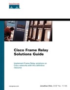
Figure 18-1 illustrates an example of a QoS policy configuration created using MQC. The purposes and the use of the new commands shown in the MQC configuration example are explained after the figure. The main objective in this section is use this configuration example to illustrate the hierarchical structure of the MQC for setting up QoS traffic policies.

With reference to the configuration example shown in Figure 18-1, the first configuration step involved in the creation of a QoS traffic policy using MQC is traffic classification. A traffic class is used to classify traffic entering or leaving the interface where the traffic policy is applied. If the contents of the packets match the conditions specified in a traffic class, then the identified traffic is a member of that traffic class. A QoS traffic policy can have a single traffic class or multiple user-defined traffic classes. A traffic class is configured with the class-map class-map-name global configuration command. Referring to the configuration example in Figure 18-1, three traffic classes are configured with the following user-defined class-map names: “Data_BRONZE,” “SNA_SILVER,” and “voice_GOLD.”
When configuring a traffic class with the class-map command, many options and criteria are available to users to classify traffic. Under the class-map command, the match commands are used to specify the criteria for identifying the packets. As packets enter or leave the interface, they are checked to determine whether they match the criteria defined in the match statement. If they do, the packets are classified as members of the traffic class. On the contrary, if the packets fail to match any user-defined traffic class, they are classified as members of the default class. One or more match statements can be configured under a class-map command, as shown previously in the “SNA_SILVER” class-map in Figure 18-1.
When setting up a traffic class with the class-map command, you can specify either the match-any or match-all option. If not specified, the default is match-any. When match-any is chosen and the class-map has multiple match statements, incoming or outgoing traffic on the interface only needs to match one of the match statements to be classified as a member of the traffic class. Conversely, when match-all is used, all match statements in the class-map must be matched in order for the traffic to be associated with the traffic class.
After configuring a class-map to perform traffic classification, you have to identify the methods to classify the traffic that belong to the class-map. Traffic classification can be performed with many different methods, such as an access control list (ACL).
As shown in Figure 18-1, it is possible to define the matching criteria based on many methods, such as ACLs, protocol types, IP precedence values, CoS, and input interfaces. In the configuration example shown in Figure 18-1, an extended access list 101 is configured to identify traffic that belongs to the “Data_BRONZE” traffic class. Example 18-1 shows the possible methods for the match command.
Example 18-1. match Command Options When Configuring class-map
Router(config)#class-map ?
  WORD       class-map name
  match-all  Logical-AND all matching statements under this classmap
  match-any  Logical-OR all matching statements under this classmap

Router(config)#class-map GOLD
Router(config-cmap)#match ?
  access-group         Access group
  any                  Any packets
  class-map            Class map
  cos                  IEEE 802.1Q/ISL class of service/user priority values
  destination-address  Destination address
  input-interface      Select an input interface to match
  ip                   IP specific values
  mpls                 Multi Protocol Label Switching specific values
  not                  Negate this match result
  protocol             Protocol
  qos-group            Qos-group
  source-address       Source address
After defining the traffic classes with the class-map command to classify the different classes of traffic that an interface might receive or transmit, the next step requires the setup of a traffic policy with the policy-map global configuration command. Similar to the class-map configuration command, the policy-map needs a user-defined name to differentiate a traffic policy from other traffic policies on the router.
As shown in Figure 18-1, “CBWFQ_policy” identifies the name of a traffic policy configured on the router. Within the traffic policy, the user needs to associate the class-maps with the traffic policy and decide the action to be performed on each identified class of traffic. Inside a policy-map, the class command is used to reference the name of a particular configured class-map. This step enters the user into the policy-map-class configuration mode. In this mode, the user sets up the QoS actions to be performed on the traffic matched by the corresponding class-map. Example 18-2 shows the list of possible QoS actions that can be performed on the traffic matched by the GOLD class-map.
Example 18-2. Possible QoS Actions for a Classified Traffic Class in a policy-map
Router(config)#policy-map EXAMPLE
Router(config-pmap)#class GOLD
Router(config-pmap-c)#?
QoS policy-map class configuration commands:
  bandwidth       Bandwidth
  default         Set a command to its defaults
  exit            Exit from QoS class action configuration mode
  no              Negate a command or set its defaults
  police          Police
  priority        Strict Scheduling Priority for this Class
  queue-limit     Queue Max Threshold for Tail Drop
  random-detect   Enable Random Early Detection as drop policy
  service-policy  Configure QoS Service Policy
  shape           Traffic Shaping
  <cr>
  set             Set QoS values
In the example shown in Figure 18-1, the “CBWFQ_policy” policy-map defines the QoS actions to be performed on each category of traffic matched by the conditions set up in the class-maps. The bandwidth percent command is used to allocate a percentage of the total bandwidth that can be consumed by traffic matched by the conditions specified in the associated class-map. In this example, 50 percent of the total bandwidth can be allocated to traffic matched by the class-map voice_GOLD. All traffic carrying an IP precedence of 5 belongs to the class-map voice_GOLD. In other words, the QoS policy allocates up to 50 percent of the total bandwidth to traffic with IP precedence 5.
Incoming or outgoing traffic on the interface that does not match the voice_GOLD class-map is matched against the conditions specified in the remaining class-maps in a top-down approach. If the traffic does not match any of the user-defined class-maps, the traffic matches the class-default class-map, and the QoS actions configured in the class-default class-map are performed. In this example, traffic not matching any of the user-defined class-maps is fair queued.
The final step in Figure 18-1 entails attaching the traffic policy to an active interface on the router via the service-policy command. The service-policy command can be used to apply the traffic policy to either incoming or outgoing traffic. In Figure 18-1, the service-policy output CBWFQ_policy command directly applies the “CBWFQ_policy” traffic policy to all traffic leaving interface serial4/0 on the router.
The configuration example shown in this section serves to familiarize the reader with the steps involved in setting up QoS policies using MQC. Both CBWFQ and LLQ are configured with MQC. You will come across more configuration examples involving MQC later on in this chapter.
This section looks at an advanced queuing feature for Frame Relay known as CBWFQ. CBWFQ is essentially an extension of the original flow-based WFQ algorithm discussed in detail in Chapter 17, “Frame Relay Congestion Management.” In contrast to WFQ, CBWFQ allows and supports up to 64 user-defined traffic classes. Figure 18-2 illustrates the basic concepts of CBWFQ. The next section discusses how WFQ and CBWFQ compare.

In the previous chapter, the WFQ algorithm was briefly introduced. Before diving into the discussion on CBWFQ in this chapter, the next section revises what you learned about WFQ. The direct comparison between CBWFQ and WFQ allows you to understand the differences and applications of the two queuing mechanisms.
The standard WFQ mechanism provides traffic priority management that automatically sorts among individual traffic streams without requiring the user to define access lists or any other forms of controls. Using a dynamic scheduling method, WFQ provides fair bandwidth allocation to all network traffic. Weights are applied to the identified traffic to classify it into conversations, or flows. The standard WFQ determines how much bandwidth will be given to each conversation. However, all traffic is treated fairly by WFQ based on the weights in a dynamic manner. For example, WFQ addresses the requirements of interactive traffic without penalizing traffic such as FTP file transfers.
WFQ is the default queuing strategy on all interfaces with a speed of E1 (2.048 Mbps) and below. For other interfaces supporting a speed greater than E1, the default queuing used is FIFO. WFQ can be disabled with the no fair-queue interface configuration command. It is replaced by FIFO if there are no other queuing mechanisms configured on the interface. To enable WFQ again on an interface if it has been previously disabled, use the fair-queue interface configuration command as follows:
fair-queue [congestive-discard-threshold [dynamic-queues [reservable-queues]]]
The configuration for WFQ on an interface does not require any parameters to be specified. However, WFQ supports a few optional configuration parameters to allow the user to customize WFQ. The configurable options are as follows:
The congestive-discard-threshold option specifies the number of messages allowed in each queue. The value must be a power of 2 in the range from 16 to 4096. The default value is 64 messages. New messages are discarded when a conversation reaches this threshold.
The dynamic-queues option indicates the number of dynamic queues to be used for best-effort conversations not requiring any special services.
The reservable-queues option sets the number of reservable queues for use by features such as Resource Reservation Protocol (RSVP). The configurable range is 0 to 1000, and the default value is 0.
Unlike with WFQ, a user can manipulate the weight for a class in CBWFQ. Configuring CBWFQ involves three major steps:
CBWFQ entails setting up traffic classes based on match criteria such as access lists, input interfaces, or protocol types. When incoming packets arrive, the packets are matched with the criteria specified in the traffic classes. Packets matching the criteria for a class constitute the traffic for that traffic class. In CBWFQ, a queue is reserved for each traffic class, and traffic belonging to a traffic class is directed to the queue for that class.
After defining the match criteria for each traffic class, the user must determine the characteristics for the class by defining appropriate actions for traffic matching that class. For example, the user can specify the bandwidth, maximum queue limit, or the drop policy to a class.
When bandwidth is used to characterize a class, the assigned bandwidth indicates the guaranteed bandwidth delivered to the class during network congestion. When queue limit is used, the maximum number of packets allowed to accumulate in the queue for the class is specified. If a drop policy is not specified for a traffic class, then Tail Drop is used by default. When Tail Drop is in use, enqueuing of an additional packet to a queue that has already reached its configured queue limit causes that packet to be dropped. On the other hand, CBWFQ supports Weighted Random Early Detection (WRED), which allows packets to be randomly dropped based on their precedence value. For instance, when WRED is used, packets with a lower precedence are dropped than packets with a higher precedence. Among the low-precedence packets, WRED can be configured so that 10 percent of the low-precedence packets are randomly dropped.
CBWFQ supports the use of a default class. The default class is specified in a policy-map as class-default. The default class in CBWFQ can be configured to treat all unclassified traffic based on bandwidth or other policies. For example, if bandwidth is used, all unclassified traffic in the default class is treated according to the configured bandwidth. In addition, WFQ can be configured in CBWFQ so that the traffic is flow classified and fairly treated. If no default class is configured, by default, all unclassified traffic that does not match any of the configured classes is flow classified and treated by WFQ.
Unlike in WFQ, the weight for a packet is derived from the bandwidth assigned to the class in CBWFQ. Hence, the weight is user-configurable in CBWFQ, because it allows the user to specify the exact amount of bandwidth to be allocated for a specific class of traffic. Depending on the amount of bandwidth available at the interface, up to 64 classes can be configured. The user has full control of the distribution of bandwidth among them. This is not possible with WFQ. As for traffic classification, CBWFQ allows the user to define the criteria that constitute a class. For WFQ, this is based only on a flow basis.
This section discusses the configuration tasks for enabling CBWFQ on Frame Relay PVCs. CBWFQ is configured via the MQC configuration interface; MQC was explained at the beginning of this chapter. Table 18-1 lists the configuration options available for setting up the traffic classes. Table 18-2 displays the class policy configurations available.
Table 18-1. Available Options for Setting Up the Traffic Class (class-map)
Command (config-cmap) | Purpose |
|---|---|
match access-group {access-group | name access-group-name} | The content of the packets is checked against the access list or named access list to determine if they belong to the class. |
match input-interface interface-name | This checks the input interface of the packets to determine if they belong to the class. |
match protocol protocol | This checks the packets to determine if they belong to a given protocol and hence, to the class. |
match mpls experimental number | This checks the EXP field in the packets to determine if they belong to the class. |
Table 18-2. Available Options for Setting Up the Class Policy (policy-map)
Command (config-pmap-c) | Purpose |
|---|---|
bandwidth [percent percent] or bandwidth kbps | This specifies the amount of bandwidth in kbps to be assigned to the class. The user should consider the Layer 2 overhead in the configured bandwidth. Note that beginning with Cisco IOS Release 12.1(1), the percent keyword is supported, and bandwidth can be assigned as a percentage. |
queue-limit | This specifies the maximum number of packets that can be enqueued for the class. This uses the Tail Drop method. |
random-detect | This enables WRED. The class policy drops packets using WRED instead of Tail Drop. WRED is explained in more detail in Chapter 21, “Weighted Random Early Detection (WRED) for Frame Relay.” |
fair-queue (applicable to class-default only) | This specifies the number of dynamic queues to be reserved for use by flow-based WFQ running on the default class. |
priority kbps | This creates a strict priority class and specifies the amount of bandwidth in kbps to be assigned to the class. |
NOTE
CBWFQ is introduced in Cisco IOS Release 12.0(5)T. CBWFQ for Frame Relay is supported on c2600, c3600, and c7200 series routers in Cisco IOS Release 12.1(2)T or later. On the c7500 series with VIP, distributed CBWFQ mode is supported in Cisco IOS Release 12.1(5)T or later.
To set up CBWFQ for Frame Relay on a Cisco router, the user first needs to configure the CBWFQ policy using the MQC. In addition, if your router platform supports Frame Relay Traffic Shaping, FRTS should be enabled for the Frame Relay interface that uses CBWFQ. After these steps are accomplished, the CBWFQ policy needs to be attached to the Frame Relay interface. There are several options available with regard to where the service policy can be applied.
First of all, the policy-map created for CBWFQ can be applied to a Frame Relay map class if CBWFQ needs to be applied to a Frame Relay subinterface or directly to a Frame Relay PVC. Frame Relay Traffic Shaping has to be enabled at the main interface on platforms that support Frame Relay Traffic Shaping. On c7500 series routers, Distributed Traffic Shaping (DTS) is supported, and the shape command has to be used in the policy-map to implement shaping. DTS combines Generic Traffic Shaping (GTS) and Frame Relay Traffic Shaping.
NOTE
As of Cisco IOS Release 12.1(5)T, QoS policies must run in distributed mode on the VIP because RSP-based QoS is no longer supported.
If the configured policy-map is applied directly at the main interface level, the CBWFQ mechanism applies to a single interface queue rather than at the per-PVC level queues.
Figure 18-3 shows the topology of the network used to demonstrate CBWFQ. The scenario presented in this example shows how CBWFQ can be used to allocate bandwidth to different classes of traffic on a heterogeneous network. It should be noted here that this scenario only serves as an example. The accompanying configuration examples are not cast in stone because of the varying characteristics and requirements of every network.

As shown in Figure 18-3, routers R1 and R2 are connected to a Frame Relay network. Router R1 represents a spoke office location connected to the central office via a Frame Relay network, at a relatively slow access rate of 64 kbps. The Frame Relay network allows the sites to burst above their respective CIR rates when the traffic is light. R1 serves several remote users at its location, who need to frequently access the main Web server at the central office. The finance administrator at the spoke location with the static address 10.0.0.2/24 needs to upload daily revenue information via a TCP application. At the same time, the company is considering a voice over IP (VoIP) implementation on its network and has installed trial phones on its routers.
The configuration examples for the routers in Figure 18-3 are shown in Example 18-3.
Example 18-3. Configuration Examples of Routers in Figure 18-3
! Router R1:

class-map match-any deluxe
  match ip precedence 5
  match access-group name UDP
class-map match-all premium
  match access-group 101
!
policy-map CBWFQ
  class premium
   bandwidth 32
  class deluxe
   bandwidth 16
   queue-limit 80
  class class-default
   fair-queue
!
interface FastEthernet0/0
 ip address 10.0.0.1 255.255.255.0
!
interface Serial4/0
 no ip address
 encapsulation frame-relay
 no fair-queue
 frame-relay traffic-shaping
!
interface Serial4/0.102 point-to-point
 ip address 172.16.1.1 255.255.255.252
 frame-relay interface-dlci 102
  class CBWFQ_class
!
router eigrp 1
 network 172.16.1.0 0.0.0.3
 network 10.0.0.0 0.0.0.255
!
ip access-list extended UDP
 permit udp any any gt 10000
!
!
map-class frame-relay CBWFQ_class
 frame-relay cir 96000
 frame-relay mincir 64000
 frame-relay adaptive-shaping becn
 service-policy output CBWFQ
!
access-list 101 permit ip host 10.0.0.2 any
!
dial-peer voice 1 pots
 destination-pattern 4001
!
dial-peer voice 2 voip
 destination-pattern 4002
 ip precedence 5
 session target ipv4:172.16.1.2
________________________________________________________________
! Router R2:

interface FastEthernet0/1
 ip address 192.168.1.1 255.255.255.0
 no ip mroute-cache
 duplex auto
 speed auto
 no cdp enable
!
interface Serial2/1
 no ip address
 encapsulation frame-relay
 no ip mroute-cache
 no fair-queue
 clockrate 128000
 frame-relay class FRTS
 frame-relay traffic-shaping
!
interface Serial2/1.201 point-to-point
 ip address 172.16.1.2 255.255.255.252
 frame-relay interface-dlci 201
!
router eigrp 1
 network 172.16.1.0 0.0.0.3
 network 192.168.1.0 0.0.0.255
!
map-class frame-relay FRTS
 frame-relay cir 512000
 frame-relay mincir 256000
 frame-relay adaptive-shaping becn
 !
dial-peer voice 1 pots
 destination-pattern 4002
!
dial-peer voice 2 voip
 destination-pattern 4001
 ip precedence 5
 session target ipv4:172.16.1.1
As shown in Example 18-3, CBWFQ is configured on Frame Relay DLCI 102 at router R1. R1 has a guaranteed access rate of 64 kbps. Because of the different classes of traffic that run on the network, CBWFQ is selected as the queuing mechanism to allocate bandwidth among the different types of traffic. Half of the available bandwidth is allocated to the premium traffic class with the bandwidth command in the class-map premium configurations. The premium class matches traffic based on access list 101, which is in turn matched to all IP traffic from host 10.0.0.2.
Next, 16 kbps is assigned to traffic that matches either named access-list UDP or any traffic with IP precedence set to critical (5). The VoIP traffic between the sites is assigned the precedence of 5.
Traffic not matching any of the criteria set up in the user-defined class-maps goes into the default class. The WFQ scheme is applied to traffic in this default class. The completed policy-map is attached to the CBWFQ_class map-class configuration for Frame Relay. This is assigned to DLCI 102.
Finally, Frame Relay Traffic Shaping is configured at the main serial interface 4/0. The CIR rate is set to 96 kbps, and the minimum CIR rate is fixed at the guaranteed 64 kbps in the Frame Relay map class. This Frame Relay Traffic Shaping configuration allows traffic on DLCI 102 to burst up to 96 kbps during no congestion. Some carriers allow their customers to burst up to the port speed when there is no congestion. When congestion occurs in the Frame Relay network, the output rate can step back to the guaranteed rate of 64 kbps. The CBWFQ mechanism ensures traffic belonging to the defined classes of traffic receive the allocated share of bandwidth.
It is important to mention that the user should ensure that the amount of bandwidth configured is large enough to accommodate all overhead, such as the Layer 2 overhead.
The next section looks at the commands for monitoring CBWFQ for the examples in Figure 18-3.
The show policy-map privileged EXEC command can be used to display the configurations of all classes comprising the specified service policy map or all classes for all existing policy maps. A sample output of the show policy-map command is shown in Example 18-4.
Example 18-4. Output of show policy-map Command at R1
R1#show policy-map
  Policy Map CBWFQ
    Class premium
      Weighted Fair Queueing
            Bandwidth 32 (kbps) Max Threshold 64 (packets)
    Class deluxe
      Weighted Fair Queueing
            Bandwidth 16 (kbps) Max Threshold 80 (packets)
    Class class-default
      Weighted Fair Queueing
            Flow based Fair Queueing Max Threshold 64 (packets).
The show policy-map interface command can be used to view the policy-map currently attached to the specified interface. A sample output is shown in Example 18-5.
Example 18-5. Output of show policy-map interface Command at R1
R1#show policy-map inter s4/0.102
 Serial4/0.102: DLCI 102 -

  Service-policy output: CBWFQ (1641)

    Class-map: premium (match-all) (1643/2)
      285808 packets, 28580800 bytes
      5 minute offered rate 32000 bps, drop rate 0 bps
      Match: access-group 101 (1647)
      Weighted Fair Queueing
        Output Queue: Conversation 25
        Bandwidth 32 (kbps) Max Threshold 64 (packets)
        (pkts matched/bytes matched) 285808/28580800
        (depth/total drops/no-buffer drops) 0/0/0

    Class-map: deluxe (match-any) (1651/3)
      369 packets, 91512 bytes
      5 minute offered rate 0 bps, drop rate 0 bps
      Match: ip precedence 5  (1655)
        369 packets, 91512 bytes
        5 minute rate 0 bps
      Match: access-group name UDP (1659)
        0 packets, 0 bytes
        5 minute rate 0 bps
      Weighted Fair Queueing
        Output Queue: Conversation 26
        Bandwidth 16 (kbps) Max Threshold 80 (packets)
        (pkts matched/bytes matched) 369/91512
        (depth/total drops/no-buffer drops) 0/0/0

    Class-map: class-default (match-any) (1663/0)
      571854 packets, 57244662 bytes
      5 minute offered rate 64000 bps, drop rate 27000 bps
      Match: any  (1667)
      Weighted Fair Queueing
        Flow Based Fair Queueing
        Maximum Number of Hashed Queues 16
        (total queued/total drops/no-buffer drops)
                       64/248543/0
The show frame-relay pvc DLCI privileged EXEC command can be used to verify and troubleshoot CBWFQ on a Cisco router. When CBWFQ is configured at the Frame Relay PVC level, the output of the show frame-relay pvc DLCI command shows additional detailed information, such as the name of the service policy attached, the number of packets matched to each class-map in the policy, and the number of packets transmitted, enqueued and dropped. The sample output in Example 18-6 shows the information displayed by the show frame-relay pvc DLCI command at R1 after traffic has been active on the Frame Relay network.
Example 18-6. Output of show frame-relay pvc 102 at R1
R1#show frame-relay pvc 102

PVC Statistics for interface Serial4/0 (Frame Relay DTE)

DLCI = 102, DLCI USAGE = LOCAL, PVC STATUS = ACTIVE, INTERFACE = Serial4/0.102

  input pkts 1530          output pkts 140100       in bytes 160329
  out bytes 13509272       dropped pkts 0           in FECN pkts 0
  in BECN pkts 0           out FECN pkts 0          out BECN pkts 0
  in DE pkts 0             out DE pkts 0
out bcast pkts 20        out bcast bytes 6980
Shaping adapts to BECN
  pvc create time 1w0d, last time pvc status changed 1w0d
  cir 96000     bc 96000     be 0         byte limit 1500   interval 125
  mincir 64000     byte increment 1500  Adaptive Shaping BECN
  pkts 98938     bytes 9953392   pkts delayed 98938     bytes delayed 9953392
  shaping active
  traffic shaping drops 41219
  service policy CBWFQ

  Service-policy output: CBWFQ (1641)

    Class-map: premium (match-all) (1643/2)
      46317 packets, 4631700 bytes
5 minute offered rate 32000 bps, drop rate 0 bps
      Match: access-group 101 (1647)
           Weighted Fair Queueing
             Output Queue: Conversation 25
             Bandwidth 32 (kbps) Max Threshold 64 (packets)
             (pkts matched/bytes matched) 47118/4711800
        (depth/total drops/no-buffer drops) 0/0/0

    Class-map: deluxe (match-any) (1651/3)
      369 packets, 91512 bytes
      5 minute offered rate 0 bps, drop rate 0 bps
      Match: ip precedence 5  (1655)
        369 packets, 91512 bytes
        5 minute rate 0 bps
      Match: access-group name UDP (1659)
        0 packets, 0 bytes
        5 minute rate 0 bps
           Weighted Fair Queueing
             Output Queue: Conversation 26
             Bandwidth 16 (kbps) Max Threshold 80 (packets)
             (pkts matched/bytes matched) 369/91512
        (depth/total drops/no-buffer drops) 0/0/0

Class-map: class-default (match-any) (1663/0)
      94274 packets, 9437360 bytes
      5 minute offered rate 64000 bps, drop rate 27000 bps
      Match: any  (1667)
           Weighted Fair Queueing
             Flow Based Fair Queueing
             Maximum Number of Hashed Queues 16
        (total queued/total drops/no-buffer drops)
                       63/42070/0
Output queue size 64/max total 600/drops 42070
Analyzing the output of show frame-relay pvc command in Example 18-6, you can see that 32 kbps of bandwidth is used by traffic belonging to the premium class, while about 64 kbps of bandwidth is used by traffic from the default class. The router is now transmitting at the CIR rate when there is no congestion, and the CIR rate is controlled by FRTS. When congestion occurs, the rate can be throttled down to the guaranteed rate of 64 kbps.
As shown in the show frame-relay pvc output, during no congestion, the aggregate throughput is about 96 kbps. 64 kbps of bandwidth (96 kbps minus 32 kbps used by the premium class) is now available to deluxe class and the default class.
Also observe in the output that there is no traffic that belongs to the deluxe class showing up. Because there is no active traffic from the deluxe class, all available bandwidth can be reused by other traffic comprising the premium class or the default class (which is all traffic not matched by any user-defined class-map).
Note that although 32 kbps and 16 kbps are reserved for traffic from the premium and deluxe classes, they can use up more than their allocated share of the bandwidth if more premium or deluxe traffic arrives. In other words, they are not policed. If the premium or deluxe traffic is transmitting at a rate much higher than its assigned bandwidth, limited bandwidth is available for traffic from the default class. WFQ can be removed and the bandwidth command can be used under the default class to allocate a minimum share of bandwidth to default traffic in order to prevent this condition.
This can be verified by removing fair-queue from the class-default class and adding bandwidth 16 to allocate the remaining 16 kbps to the class-default class. This change ensures that when traffic from all classes is bursting, traffic from the default class gets a share of the service. Example 18-7 shows the output of the resultant changes.
Example 18-7. Output of show frame-relay pvc at R1 After Allocating Bandwidth to the Default Class
R1#show frame-relay pvc 102

PVC Statistics for interface Serial4/0 (Frame Relay DTE)

DLCI = 102, DLCI USAGE = LOCAL, PVC STATUS = ACTIVE, INTERFACE = Serial4/0.102
  input pkts 1294          output pkts 163173       in bytes 95394
  out bytes 15681306       dropped pkts 0           in FECN pkts 0
  in BECN pkts 0           out FECN pkts 0          out BECN pkts 0
  in DE pkts 0             out DE pkts 0
  out bcast pkts 66        out bcast bytes 23034
  Shaping adapts to BECN
  pvc create time 1w1d, last time pvc status changed 1w1d
  cir 64000     bc 64000     be 0         byte limit 1000   interval 125
  mincir 64000     byte increment 1000  Adaptive Shaping BECN
  pkts 71892     bytes 7205634   pkts delayed 71821     bytes delayed 7185835
  shaping active
  traffic shaping drops 91211
  service policy CBWFQ

  Service-policy output: CBWFQ (2037)

    Class-map: premium (match-all) (2039/2)
      51382 packets, 5138200 bytes
      5 minute offered rate 48000 bps, drop rate 16000 bps
      Match: access-group 101 (2043)
      Weighted Fair Queueing
        Output Queue: Conversation 25
        Bandwidth 32 (kbps) Max Threshold 64 (packets)
        (pkts matched/bytes matched) 103392/10339200
        (depth/total drops/no-buffer drops) 63/25340/0

    Class-map: deluxe (match-any) (2047/3)
      144664 packets, 14466400 bytes
      5 minute offered rate 48000 bps, drop rate 32000 bps
      Match: ip precedence 5  (2051)
        0 packets, 0 bytes
        5 minute rate 0 bps
      Match: access-group name UDP (2055)
        144664 packets, 14466400 bytes
        5 minute rate 48000 bps
      Weighted Fair Queueing
        Output Queue: Conversation 26
        Bandwidth 16 (kbps) Max Threshold 80 (packets)
        (pkts matched/bytes matched) 145059/14505900
        (depth/total drops/no-buffer drops) 80/105933/0

    Class-map: class-default (match-any) (2059/0)
      69280 packets, 6968338 bytes
      5 minute offered rate 48000 bps, drop rate 32000 bps
      Match: any  (2063)
      Weighted Fair Queueing
        Output Queue: Conversation 27
        Bandwidth 16 (kbps) Max Threshold 64 (packets)
        (pkts matched/bytes matched) 69684/6968400
        (depth/total drops/no-buffer drops) 64/46493/0
  Output queue size 208/max total 600/drops 177930
As shown in Example 18-7, traffic from the premium, deluxe, and default classes is allocated 32 kbps, 16 kbps, and 16 kbps of bandwidth, respectively. To illustrate this example, the CIR is lowered to 64 kbps to remove oversubscription.
Note that the Cisco IOS CLI rejects any attempt by the user to allocate additional bandwidth to the policy-map if the resultant changes cause the aggregate bandwidth in the policy-map to exceed the total bandwidth available at the interface. Example 18-8 shows the Cisco IOS CLI rejecting an attempt to increase the bandwidth of the premium class because the aggregate bandwidth in the CBWFQ policy-map has now exceeded 64 kbps.
Example 18-8. Attempt to Increase Bandwidth Is Rejected by CLI
R1(config)#policy-map CBWFQ R1(config-pmap)#class premium R1(config-pmap-c)#bandwidth 33 I/f Serial4/0.102 DLCI 102 Class premium requested bandwidth 33 (kbps) Only 0 (kbps)available
The bandwidth percent command can also be used to allocate traffic as a percentage of the available bandwidth. Remember that when the percent keyword is used, all the class bandwidths must be specified as percentages. A mix of both kbps and percent is not allowed.
This example concludes the discussion of CBWFQ on Frame Relay. In the next section, a new exciting queuing strategy known as LLQ, or PQ/CBWFQ, is discussed. Since LLQ was developed, it has been widely adopted and used on voice/data networks.
With the emergence of voice traffic into data networks, the need to differentiate between the various classes of service has become greater. PQ/CBWFQ, most commonly known as LLQ, is a new feature that provides a strict priority queue for voice traffic and a weighted fair queue for each of the other classes of traffic. LLQ brings strict priority queuing to the CBWFQ scheme. Figure 18-4 illustrates the basic concepts of how LLQ works.
Without LLQ, the CBWFQ scheme provides WFQ to classes of traffic defined by the user, but there is no strict priority queue for delay-sensitive traffic, such as voice. CBWFQ allows the user to reserve a minimum bandwidth for a class during congestion. However, this scheme does not work well for voice traffic, which is intolerant of delay. Delay in voice traffic results in irregular transmission causing jitter in the heard conversation. For good voice quality, the one-way end-to-end delay should ideally be less than 150 milliseconds (ms). The new feature provided by LLQ is especially important for ensuring voice quality on slow-speed links.
With LLQ, a strict priority queuing scheme improves the QoS by allowing delay-sensitive traffic, such as voice, to be dequeued from the queuing system and sent before other classes of traffic. The priority queue is also policed to ensure that the fair queues are not starved of bandwidth. Packets that exceed the configured maximum in the PQ are dropped. Although LLQ is most commonly deployed on mixed voice/data networks for voice traffic, other mission-critical traffic can be classified and transmitted from the priority queue.
LLQ offers much more flexibility than previous Frame Relay QoS features, such as Real-Time Protocol (RTP) prioritization and PQ/WFQ for Frame Relay. With RTP prioritization and PQ/WFQ, traffic that matches a specified UDP/RTP port range is considered high priority and allocated to the PQ. LLQ allows the user to define classes of traffic based on protocols, source interfaces, or access lists. Each class of traffic can be assigned characteristics, such as priority, bandwidth, queue-limit, and random-detect (WRED), in a way similar to CBWFQ.
LLQ for Frame Relay is related to several QoS features for Frame Relay and can be used in conjunction with them. The Frame Relay QoS features related to LLQ are the following:
Frame Relay Traffic Shaping—. To use LLQ for Frame Relay, Frame Relay Traffic Shaping must be enabled on the main interface. FRTS is a prerequisite for LLQ. This is verified in the examples in the later sections of this chapter.
RTP Prioritization for Frame Relay—. The RTP Prioritization for Frame Relay feature provides a strict priority queuing scheme for voice traffic. The voice traffic is identified by its RTP port numbers and classified into a priority queue using the frame-relay ip rtp priority map-class configuration command. When RTP Prioritization is used in conjunction with LLQ, voice traffic that matches the specified range is queued in the LLQ PQ and the interface priority queue.
Voice over Frame Relay (VoFR)—. When VoFR is configured in conjunction with LLQ, it uses the LLQ PQ rather than its own priority queuing mechanism. VoFR is enabled with the frame-relay voice bandwidth map-class configuration command, which sets the total bandwidth made available to VoFR traffic. The vofr data command is supported with LLQ for Frame Relay. When VoFR has no data, all the voice and call control packets are queued in the VC priority queue. For VoFR with data, a FRF.11 PVC can carry both voice and data packets in different subchannels. The FRF.11 data packets are fragmented and interleaved with the voice packets.
Frame Relay Fragmentation (FRF.12)—. Frame Relay Fragmentation (FRF.12) is used to support voice and data packets on lower-speed links without causing excessive delay to the voice packets. When FRF.12 is configured, the smaller voice packets queued in the priority queue are sent unfragmented. Large data packets classified to the priority queue are fragmented when dequeued. This causes the fragmented data packets to be interleaved with the unfragmented voice packets. This interleaving ensures minimum delay for the delay-sensitive voice packets.
IP Cisco Express Forwarding (CEF) Switching—. The IP CEF switching functionality is transparent to LLQ for Frame Relay and is expected to work with LLQ for Frame Relay.
In Cisco IOS Release 12.1(2)T, the LLQ for Frame Relay feature is not compatible with certain legacy Frame Relay features. When using LLQ for Frame Relay with an earlier supported Cisco IOS release, please ensure the Frame Relay features listed in this section are not configured together with LLQ. The following Frame Relay features are not supported with LLQ for Frame Relay:
Frame Relay switching
GTS
Traffic shaping commands in MQC CLI
Fancy queuing: Frame Relay priority queuing and Frame Relay custom queuing
In addition, any queue other than a FIFO queue that is configured in the Frame Relay map class must be removed. LLQ for Frame Relay cannot be used if there is already a non-FIFO queue configured, except for the default queue created when fragmentation is enabled.
In the next section, a simple scenario illustrates how LLQ can be configured on a Cisco router to support voice and data traffic on a heterogeneous network.
The LLQ for Frame Relay feature is available in Cisco IOS Release 12.1(2)T or later and is supported on c805, c1600, c1700, c2500, c2600, c3600, c3810, and c7200 series routers. The latest Cisco IOS release might support the LLQ for Frame Relay feature on the newer Cisco router platforms, such as c2600-XM, c3700, and c7600.
The Cisco MQC interface CLI is used to configure LLQ for Frame Relay. To configure LLQ for Frame Relay, the queues are set up on a per-PVC basis. Each VC has a PQ and an assigned number of fair queues. In a manner identical to CBWFQ, LLQ for Frame Relay is configured with a combination of class-map, policy-map, and Frame Relay map-class commands. Traffic classes are set up with the class-map command to classify the traffic. The user determines how the traffic is classified based on protocols, source interfaces, or access lists. Then the policy-map command is used to create a traffic policy whereby the user can configure how each class of traffic is treated in the queuing system. The policies can be based on priority (PQ), bandwidth, queue limit, or WRED. Finally, the policy-map is attached to a Frame Relay VC using the service-policy output command in the Frame Relay map class. The map class is, in turn, assigned to the Frame Relay DLCI.
If you skipped the earlier sections on MQC interface CLI or CBWFQ, reading those sections to become familiarized with the configuration tasks for MQC or CBWFQ is recommended. Otherwise, Figure 18-5 shows the topology of the network that is used to illustrate LLQ for Frame Relay.

Figure 18-5 illustrates the scenario of a small firm that has a central office connected to several branch offices across a nationwide Frame Relay network. The firm wishes to leverage on VoIP and multicast to support desktop video conferencing applications on its network. To optimize the application performance for the real-time traffic on the network, the firm needs to manage the network performance with respect to bandwidth, delay, jitters, and packet loss. In addition, the firm needs to service the needs of other applications running over the WAN. Hence, the firm decides to implement LLQ on its Frame Relay network. A strict priority queue is created to minimize delay for the real-time delay-sensitive traffic. LLQ polices the real-time traffic in the strict priority queue and ensures that other nonpriority traffic on the network, such as SNA and sales data transfers, is not starved of bandwidth.
NOTE
The network implementer advised the firm against using oversubscription, because it usually leads to packet discards and might result in poor voice/video quality.
The network in Figure 18-5 is set up, and the configurations of the routers are shown in Example 18-9. Notice that only the configurations of routers R1 and R2 are shown in Example 18-9, because the configurations for R3 or R4 are very similar to those of R2.
Example 18-9. Configurations of the Routers in Figure 18-5
! Router R1:

<output omitted>

class-map match-all SALES_DATA
  match access-group 103
class-map match-any SNA_DATA
  match protocol dlsw
  match access-group 102
class-map match-all VIDEO
  match access-group 101
!
!
policy-map LLQ
  class VIDEO
    priority 64
  class SNA_DATA
   bandwidth 32
   queue-limit 100
  class SALES_DATA
   bandwidth 16
  class class-default
   fair-queue
!
interface FastEthernet0/0
 ip address 10.0.0.1 255.255.255.0
!
interface Serial4/0
 no ip address
 encapsulation frame-relay
 no fair-queue
 frame-relay traffic-shaping
!
interface Serial4/0.102 point-to-point
 ip address 172.16.1.1 255.255.255.252
 frame-relay interface-dlci 102
  class LLQ_class
!
interface Serial4/0.103 point-to-point
 ip address 172.16.1.5 255.255.255.252
 frame-relay interface-dlci 103
  class LLQ_class
!
interface Serial4/0.104 point-to-point
 ip address 172.16.1.9 255.255.255.252
 frame-relay interface-dlci 104
  class LLQ_class
!
!
map-class frame-relay LLQ_class
 frame-relay cir 128000
 frame-relay mincir 128000
 no frame-relay adaptive-shaping
 service-policy output LLQ
!
ip route 20.0.0.0 255.255.255.0 172.16.1.2
ip route 30.0.0.0 255.255.255.0 172.16.1.6
ip route 40.0.0.0 255.255.255.0 172.16.1.10
!
access-list 101 permit udp any any eq 12000
access-list 102 permit tcp any eq 2065 any
access-list 102 permit tcp any any eq 2065
access-list 103 permit tcp host 10.0.0.2 any eq 10000
________________________________________________________________
! Router R2:

<output omitted>

class-map match-all SALES_DATA
  match access-group 103
class-map match-any SNA_DATA
  match protocol dlsw
  match access-group 102
class-map match-all VIDEO
  match access-group 101
!
!
policy-map LLQ
  class VIDEO
    priority 64
  class SNA_DATA
   bandwidth 32
   queue-limit 100
  class SALES_DATA
   bandwidth 16
  class class-default
   fair-queue
!
interface FastEthernet0/0
 ip address 20.0.0.1 255.255.255.0
!
interface Serial2/1
 no ip address
 encapsulation frame-relay
 no fair-queue
 frame-relay traffic-shaping
!
interface Serial2/1.201 point-to-point
 ip address 172.16.1.2 255.255.255.252
 frame-relay interface-dlci 201
  class LLQ_class
!
map-class frame-relay LLQ_class
 frame-relay cir 128000
 frame-relay mincir 128000
 no frame-relay adaptive-shaping
 service-policy output LLQ
!
ip route 10.0.0.0 255.255.255.0 172.16.1.1
ip route 30.0.0.0 255.255.255.0 172.16.1.1
ip route 40.0.0.0 255.255.255.0 172.16.1.1
!
access-list 101 permit udp any any eq 12000
access-list 102 permit tcp any eq 2065 any
access-list 102 permit tcp any any eq 2065
access-list 103 permit tcp host 20.0.0.2 any eq 10000
In the network diagram in Figure 18-5, each remote site has a Frame Relay VC with a minimum access speed of 128 kbps terminating into the central location. To prevent oversubscription, Frame Relay Traffic Shaping is enabled, and the routers are allowed to burst only up to the CIR rate. Hence, both the minimum CIR and the CIR are set to 128 kbps in Example 18-9.
Although bursting over Frame Relay can be attractive for data networks, it might not be desirable on integrated voice and data networks because voice packets might be dropped. A discarded voice packet can result in retransmission and cause jitter and result in poor voice quality. This can also cause slow response to the user desktop application.
The various traffic classes are defined with the class-map commands. The traffic is classified to the class-map by means of protocol types, input interfaces, or access lists. For instance, in Example 18-9, the traffic destined for the priority queue is classified with an extended access list 101 that matches UDP traffic with port number 12000. Then the CBWFQ scheme is used to serve both the SNA and sales data traffic on the network. All the remaining traffic not matched by the priority class map or the CBWFQ class maps are sent to the default class.
A policy-map named LLQ is configured to define how each identified class of traffic is handled in the traffic policy. A priority queue with a bandwidth of 64 kbps is used to service desktop video conferencing traffic running on UDP port 12000. The SNA and sales data are assigned a bandwidth of 32 kbps and 16 kbps, respectively. Traffic in the default class is serviced based on best-effort delivery using a flow-based fair queuing scheme.
The next section verifies the workings of the LLQ system by observing the outputs of the various show commands.
After the routers are configured, four different streams of traffic from the applications are transmitted over the network. The traffic information is recorded in Table 18-3.
Table 18-3. Traffic Information for Figure 18-5 Received by R1
Traffic Streams | Allocated Bandwidth | Actual Amount of Traffic Sent |
|---|---|---|
Stream 1 (UDP port 12000) | 64 kbps | 85 kbps |
Stream 2 (TCP port 2065) | 32 kbps | 34 kbps |
Stream 3 (IP source address 10.0.0.2) | 16 kbps | 18 kbps |
Stream 4 (IP traffic with source 10.0.0.3) | 16 kbps if Stream 1 and Stream 2 are sticking to their assigned bandwidth | 16 kbps |
Total Bandwidth | 128 kbps | Approximately 153 kbps |
In Table 18-3, the actual amount of traffic sent over the network is set to be slightly higher than the allowed CIR value. The main objective is to verify that when congestion arises, delay-sensitive traffic in the priority queue is allocated its reserved bandwidth and receives the service required. Moreover, observe that the LLQ system, unlike priority queue, does not starve the other traffic of the bandwidth required. CBWFQ ensures that the other classes of traffic are serviced.
The show frame-relay pvc DLCI command can be used to display information related to the per-VC queuing strategy configured on the DLCI, including LLQ. Example 18-10 shows the output of show frame-relay pvc command at router R1 after the traffic has been sent onto the network for approximately 5 minutes.
Example 18-10. Output of show frame-relay pvc at Router R1
R1#show frame-relay pvc 102

PVC Statistics for interface Serial4/0 (Frame Relay DTE)

DLCI = 102, DLCI USAGE = LOCAL, PVC STATUS = ACTIVE, INTERFACE = Serial4/0.102

  input pkts 6809          output pkts 612865       in bytes 423873
  out bytes 64024285       dropped pkts 0           in FECN pkts 0
  in BECN pkts 0           out FECN pkts 0          out BECN pkts 0
  in DE pkts 0             out DE pkts 0
  out bcast pkts 57        out bcast bytes 19893
  pvc create time 04:07:13, last time pvc status changed 04:06:53
  cir 128000    bc 128000    be 0         byte limit 2000   interval 125
  mincir 128000    byte increment 2000  Adaptive Shaping none
  pkts 498627    bytes 54344821  pkts delayed 498627    bytes delayed 54344821
  shaping active
  traffic shaping drops 114134
  service policy LLQ

  Service-policy output: LLQ (2367)

    Class-map: VIDEO (match-all) (2369/2)
      339456 packets, 36661248 bytes
5 minute offered rate 86000 bps, drop rate 22000 bps
      Match: access-group 101 (2373)
     Weighted Fair Queueing
       Strict Priority
       Output Queue: Conversation 24
       Bandwidth 64 (kbps) Burst 1600 (Bytes)
       (pkts matched/bytes matched) 342270/36965160
       (total drops/bytes drops) 88739/9583812

    Class-map: SNA_DATA (match-any) (2377/3)
      136583 packets, 14750964 bytes
      5 minute offered rate 34000 bps, drop rate 0 bps
      Match: protocol dlsw (2381)
        0 packets, 0 bytes
        5 minute rate 0 bps
      Match: access-group 102 (2385)
        136583 packets, 14750964 bytes
        5 minute rate 34000 bps
     Weighted Fair Queueing
       Output Queue: Conversation 25
       Bandwidth 32 (kbps) Max Threshold 100 (packets)
       (pkts matched/bytes matched) 136908/14786064
        (depth/total drops/no-buffer drops) 0/0/0

    Class-map: SALES_DATA (match-all) (2389/4)
      68492 packets, 8219040 bytes
      5 minute offered rate 19000 bps, drop rate 0 bps
      Match: access-group 103 (2393)
     Weighted Fair Queueing
       Output Queue: Conversation 26
       Bandwidth 16 (kbps) Max Threshold 64 (packets)
       (pkts matched/bytes matched) 68631/8235720
        (depth/total drops/no-buffer drops) 0/0/0

    Class-map: class-default (match-any) (2397/0)
      68606 packets, 6888986 bytes
      5 minute offered rate 16000 bps, drop rate 5000 bps
      Match: any  (2401)
     Weighted Fair Queueing
       Flow Based Fair Queueing
       Maximum Number of Hashed Queues 16
        (total queued/total drops/no-buffer drops)
                       64/26091/0
Output queue size 65/max total 600/drops 115060
Example 18-10 showed the output rate and other detailed information of each queue, as expected of LLQ.
In the output, the VIDEO class shows the average output rate to be approximately 86000 bps with a constant drop rate of 22000 bps. Hence, the aggregate output of the priority queue is 64000 bps, as reserved in the priority command in the VIDEO class-map. When congestion occurs and the other CBWFQ queues are fully using their allocated bandwidth, the priority queue is policed, and any excess packets exceeding the reserved bandwidth are dropped. For the SNA_DATA and SALES_DATA data queues, although 32 kbps and 16 kbps are allocated in the class-map, traffic from these classes can use up more than the allocated bandwidth, if it is available.
As seen from the output, bandwidth implicitly available to the default class is now used by traffic from the SNA_DATA and SALES_DATA classes. Around 5 kbps of bandwidth is “squeezed” from the default class, which is the cause of the constant 5 kbps of packet drop in the class-default class. To ensure traffic from the default class is guaranteed service, replace the fair-queue command with the bandwidth kbps command in the class-map for class-default.
Example 18-11 displays the output of the show interface command at router R1, which shows that the aggregate output rate is rate-limited by Frame Relay Traffic Shaping at approximately 128000 bps.
Example 18-11. Output of show interface Command at R1
R1#show interface serial4/0
Serial4/0 is up, line protocol is up
  Hardware is M4T
  MTU 1500 bytes, BW 128000 Kbit, DLY 20000 usec,
     reliability 255/255, txload 1/255, rxload 1/255
  Encapsulation FRAME-RELAY, crc 16, loopback not set
  Keepalive set (10 sec)
  LMI enq sent  502, LMI stat recvd 502, LMI upd recvd 0, DTE LMI up
  LMI enq recvd 0, LMI stat sent  0, LMI upd sent  0
  LMI DLCI 1023  LMI type is CISCO  frame relay DTE
  FR SVC disabled, LAPF state down
  Broadcast queue 0/64, broadcasts sent/dropped 251/0, interface broadcasts 0
  Last input 00:00:00, output 00:00:00, output hang never
  Last clearing of "show interface" counters 01:23:31
  Queueing strategy: fifo
  Output queue 40/40, 187539 drops; input queue 0/75, 0 drops
  5 minute input rate 0 bits/sec, 2 packets/sec
  5 minute output rate 124000 bits/sec, 142 packets/sec
     10611 packets input, 657839 bytes, 0 no buffer
     Received 0 broadcasts, 0 runts, 0 giants, 0 throttles
     0 input errors, 0 CRC, 0 frame, 0 overrun, 0 ignored, 0 abort
     715526 packets output, 78013049 bytes, 0 underruns
     0 output errors, 0 collisions, 0 interface resets
     0 output buffer failures, 0 output buffers swapped out
     0 carrier transitions     DCD=up  DSR=up  DTR=up  RTS=up  CTS=up
The output queue at the interface is seeing packet drops because the LLQ at the Frame Relay PVC level is experiencing congestion.
The subsequent examples exemplify that when the priority queue is not transmitting, the bandwidth allocated in the priority queue can be freed up for traffic from the other CBWFQ queues.
Example 18-12 shows the output of the show frame-relay pvc command at R1 after traffic comprising the priority queue from stream 1 is reduced. Traffic from the remaining queues is still being sent at the same rate as before.
Example 18-12. Output of show frame-relay pvc at Router R1 After High-Priority Traffic Is Reduced
R1#show frame-relay pvc 102

PVC Statistics for interface Serial4/0 (Frame Relay DTE)

DLCI = 102, DLCI USAGE = LOCAL, PVC STATUS = ACTIVE, INTERFACE = Serial4/0.102

  input pkts 10506         output pkts 941786       in bytes 654032
  out bytes 98387187       dropped pkts 0           in FECN pkts 0
  in BECN pkts 0           out FECN pkts 0          out BECN pkts 0
  in DE pkts 0             out DE pkts 0
  out bcast pkts 87        out bcast bytes 30363
  pvc create time 04:38:01, last time pvc status changed 04:37:41
  cir 128000    bc 128000    be 0         byte limit 2000   interval 125
  mincir 128000    byte increment 2000  Adaptive Shaping none
  pkts 766874    bytes 83579919  pkts delayed 764061    bytes delayed 83273311
  shaping inactive
  traffic shaping drops 174828
  service policy LLQ

  Service-policy output: LLQ (2367)

    Class-map: VIDEO (match-all) (2369/2)
      521479 packets, 56319732 bytes
      5 minute offered rate 74000 bps, drop rate 16000 bps
      Match: access-group 101 (2373)
     Weighted Fair Queueing
       Strict Priority
       Output Queue: Conversation 24
       Bandwidth 64 (kbps) Burst 1600 (Bytes)
       (pkts matched/bytes matched) 521479/56319732
       (total drops/bytes drops) 135203/14601924

    Class-map: SNA_DATA (match-any) (2377/3)
      210146 packets, 22695768 bytes
      5 minute offered rate 34000 bps, drop rate 0 bps
      Match: protocol dlsw (2381)
        0 packets, 0 bytes
        5 minute rate 0 bps
      Match: access-group 102 (2385)
        210146 packets, 22695768 bytes
        5 minute rate 34000 bps
     Weighted Fair Queueing
       Output Queue: Conversation 25
       Bandwidth 32 (kbps) Max Threshold 100 (packets)
       (pkts matched/bytes matched) 208629/22531932
        (depth/total drops/no-buffer drops) 0/0/0

    Class-map: SALES_DATA (match-all) (2389/4)
      105474 packets, 12656880 bytes
      5 minute offered rate 19000 bps, drop rate 0 bps
      Match: access-group 103 (2393)
     Weighted Fair Queueing
       Output Queue: Conversation 26
       Bandwidth 16 (kbps) Max Threshold 64 (packets)
       (pkts matched/bytes matched) 104315/12517800
        (depth/total drops/no-buffer drops) 0/0/0

    Class-map: class-default (match-any) (2397/0)
      105650 packets, 10608824 bytes
      5 minute offered rate 16000 bps, drop rate 0 bps
      Match: any  (2401)
     Weighted Fair Queueing
       Flow Based Fair Queueing
       Maximum Number of Hashed Queues 16
        (total queued/total drops/no-buffer drops)
                       0/39625/0
  Output queue size 0/max total 600/drops 174828
As shown in Example 18-12, as the traffic rate in the priority queue is gradually reduced, there are no longer any packets dropped in the class-default queue. As such, when the priority queue is not transmitting, traffic from the other CBWFQ queues can use up the free bandwidth.
Example 18-13 shows the output of the same show frame-relay pvc command at router R1 after all the high-priority traffic is stopped.
Example 18-13. Output of the show frame-relay pvc at Router R1 After High-Priority Traffic Is Stopped
R1#show frame-relay pvc 102

PVC Statistics for interface Serial4/0 (Frame Relay DTE)

DLCI = 102, DLCI USAGE = LOCAL, PVC STATUS = ACTIVE, INTERFACE = Serial4/0.102

  input pkts 11370         output pkts 976038       in bytes 707755
  out bytes 101985354      dropped pkts 0           in FECN pkts 0
  in BECN pkts 0           out FECN pkts 0          out BECN pkts 0
  in DE pkts 0             out DE pkts 0
  out bcast pkts 94        out bcast bytes 32806
  pvc create time 04:45:10, last time pvc status changed 04:44:50
  cir 128000    bc 128000    be 0         byte limit 2000   interval 125
  mincir 128000    byte increment 2000  Adaptive Shaping none
  pkts 801172    bytes 87320090  pkts delayed 764061    bytes delayed 83273311
  shaping inactive
  traffic shaping drops 174828
  service policy LLQ

  Service-policy output: LLQ (2367)

    Class-map: VIDEO (match-all) (2369/2)
      521479 packets, 56319732 bytes
      5 minute offered rate 0 bps, drop rate 0 bps
      Match: access-group 101 (2373)
     Weighted Fair Queueing
       Strict Priority
       Output Queue: Conversation 24
       Bandwidth 64 (kbps) Burst 1600 (Bytes)
       (pkts matched/bytes matched) 521479/56319732
       (total drops/bytes drops) 135203/14601924

    Class-map: SNA_DATA (match-any) (2377/3)
      227749 packets, 24596892 bytes
      5 minute offered rate 34000 bps, drop rate 0 bps
      Match: protocol dlsw (2381)
        0 packets, 0 bytes
        5 minute rate 0 bps
      Match: access-group 102 (2385)
        227749 packets, 24596892 bytes
        5 minute rate 34000 bps
     Weighted Fair Queueing
       Output Queue: Conversation 25
       Bandwidth 32 (kbps) Max Threshold 100 (packets)
       (pkts matched/bytes matched) 208629/22531932
        (depth/total drops/no-buffer drops) 0/0/0
    Class-map: SALES_DATA (match-all) (2389/4)
      114275 packets, 13713000 bytes
      5 minute offered rate 19000 bps, drop rate 0 bps
      Match: access-group 103 (2393)
     Weighted Fair Queueing
       Output Queue: Conversation 26
       Bandwidth 16 (kbps) Max Threshold 64 (packets)
       (pkts matched/bytes matched) 104315/12517800
        (depth/total drops/no-buffer drops) 0/0/0

    Class-map: class-default (match-any) (2397/0)
      114465 packets, 11493810 bytes
      5 minute offered rate 16000 bps, drop rate 0 bps
      Match: any  (2401)
     Weighted Fair Queueing
       Flow Based Fair Queueing
       Maximum Number of Hashed Queues 16
        (total queued/total drops/no-buffer drops)
                       0/39625/0
  Output queue size 0/max total 600/drops 174828
In Example 18-14, the opposite condition is verified. When the CBWFQ queues are not using up their allocated bandwidth, traffic from a congested priority queue can use up the free bandwidth. The high-priority traffic is resent onto the network and the traffic rate from streams 2, 3, and 4 are reduced. Example 18-14 displays the output of the show frame-relay pvc command at router R1, which shows that the priority queue is now using up the freed bandwidth from the CBWFQ queues.
Example 18-14. High-Priority Queue Traffic Using Up Bandwidth Freed from the CBWFQ Queues
R1#show frame-relay pvc 102

PVC Statistics for interface Serial4/0 (Frame Relay DTE)

DLCI = 102, DLCI USAGE = LOCAL, PVC STATUS = ACTIVE, INTERFACE = Serial4/0.102

  input pkts 13083         output pkts 1099572      in bytes 814301
  out bytes 114906617      dropped pkts 0           in FECN pkts 0
  in BECN pkts 0           out FECN pkts 0          out BECN pkts 0
  in DE pkts 0             out DE pkts 0
  out bcast pkts 109       out bcast bytes 38041
  pvc create time 04:59:25, last time pvc status changed 04:59:05
  cir 128000    bc 128000    be 0         byte limit 2000   interval 125
  mincir 128000    byte increment 2000  Adaptive Shaping none
  pkts 915475    bytes 99738465  pkts delayed 843271    bytes delayed 91875437
  shaping inactive
  traffic shaping drops 184066
  service policy LLQ

  Service-policy output: LLQ (2367)

    Class-map: VIDEO (match-all) (2369/2)
      594934 packets, 64252872 bytes
      5 minute offered rate 86000 bps, drop rate 0 bps
      Match: access-group 101 (2373)
     Weighted Fair Queueing
       Strict Priority
       Output Queue: Conversation 24
       Bandwidth 64 (kbps) Burst 1600 (Bytes)
       (pkts matched/bytes matched) 576248/62234784
       (total drops/bytes drops) 144441/15599628

    Class-map: SNA_DATA (match-any) (2377/3)
      251232 packets, 27133056 bytes
      5 minute offered rate 8000 bps, drop rate 0 bps
      Match: protocol dlsw (2381)
        0 packets, 0 bytes
        5 minute rate 0 bps
      Match: access-group 102 (2385)
        251232 packets, 27133056 bytes
        5 minute rate 8000 bps
     Weighted Fair Queueing
       Output Queue: Conversation 25
       Bandwidth 32 (kbps) Max Threshold 100 (packets)
       (pkts matched/bytes matched) 225005/24300540
        (depth/total drops/no-buffer drops) 0/0/0

    Class-map: SALES_DATA (match-all) (2389/4)
      127770 packets, 15332400 bytes
      5 minute offered rate 9000 bps, drop rate 0 bps
      Match: access-group 103 (2393)
     Weighted Fair Queueing
       Output Queue: Conversation 26
       Bandwidth 16 (kbps) Max Threshold 64 (packets)
       (pkts matched/bytes matched) 113484/13618080
        (depth/total drops/no-buffer drops) 0/0/0

    Class-map: class-default (match-any) (2397/0)
      126029 packets, 12657182 bytes
      5 minute offered rate 4000 bps, drop rate 0 bps
      Match: any  (2401)
     Weighted Fair Queueing
       Flow Based Fair Queueing
       Maximum Number of Hashed Queues 16
        (total queued/total drops/no-buffer drops)
                       0/39625/0
  Output queue size 0/max total 600/drops 184066
As observed in Example 18-14, the traffic from the priority queue is now using up bandwidth freed from the CBWFQ queues. Note that although only 64 kbps of bandwidth is reserved for the priority queue, it is now sending at a rate higher than 64 kbps because the other CBWFQ queues are not transmitting at their maximum potential.
FRTS is a prerequisite for employing the LLQ system on a Frame Relay VC. If FRTS is unconfigured at the main interface after LLQ has been enabled on a Frame Relay DLCI, the service policy is removed. Example 18-15 shows this condition.
Example 18-15. Removing FRTS After LLQ Is Configured
R1#configure terminal
Enter configuration commands, one per line.  End with CNTL/Z.
R1(config)#interface Serial4/0
R1(config-if)#no frame-relay traffic-shaping
R1(config-if)#exit
R1#show frame-relay pvc 102

PVC Statistics for interface Serial4/0 (Frame Relay DTE)

DLCI = 102, DLCI USAGE = LOCAL, PVC STATUS = ACTIVE, INTERFACE = Serial4/0.102

  input pkts 13284         output pkts 1112074      in bytes 826899
  out bytes 116215070      dropped pkts 0           in FECN pkts 0
  in BECN pkts 0           out FECN pkts 0          out BECN pkts 0
  in DE pkts 0             out DE pkts 0
  out bcast pkts 110       out bcast bytes 38390
  pvc create time 05:01:04, last time pvc status changed 05:00:44

<-- The service policy is now removed!
The show policy-map interface command can be used to display or verify information regarding the LLQ traffic policy attached to an interface. This is shown in Example 18-16.
Example 18-16. Output of show policy-map interface at Router R1
R1#show policy-map interface Serials4/0.102
 Serial4/0.102: DLCI 102 -

  Service-policy output: LLQ (2411)

    Class-map: VIDEO (match-all) (2413/2)
      36349 packets, 3925692 bytes
      5 minute offered rate 86000 bps, drop rate 0 bps
      Match: access-group 101 (2417)
      Weighted Fair Queueing
        Strict Priority
        Output Queue: Conversation 24
        Bandwidth 64 (kbps) Burst 1600 (Bytes)
        (pkts matched/bytes matched) 1/108
        (total drops/bytes drops) 0/0

    Class-map: SNA_DATA (match-any) (2421/3)
      3635 packets, 392580 bytes
      5 minute offered rate 8000 bps, drop rate 0 bps
      Match: protocol dlsw (2425)
        0 packets, 0 bytes
        5 minute rate 0 bps
      Match: access-group 102 (2429)
        3635 packets, 392580 bytes
        5 minute rate 8000 bps
      Weighted Fair Queueing
        Output Queue: Conversation 25
        Bandwidth 32 (kbps) Max Threshold 100 (packets)
        (pkts matched/bytes matched) 0/0
        (depth/total drops/no-buffer drops) 0/0/0

    Class-map: SALES_DATA (match-all) (2433/4)
      3635 packets, 436200 bytes
      5 minute offered rate 9000 bps, drop rate 0 bps
      Match: access-group 103 (2437)
      Weighted Fair Queueing
        Output Queue: Conversation 26
        Bandwidth 16 (kbps) Max Threshold 64 (packets)
        (pkts matched/bytes matched) 0/0
        (depth/total drops/no-buffer drops) 0/0/0
    Class-map: class-default (match-any) (2441/0)
      1830 packets, 185988 bytes
      5 minute offered rate 4000 bps, drop rate 0 bps
      Match: any  (2445)
      Weighted Fair Queueing
        Flow Based Fair Queueing
        Maximum Number of Hashed Queues 16
        (total queued/total drops/no-buffer drops)
                       0/0/0
This chapter introduced readers to the MQC in the Cisco IOS software, which provides users with a comprehensive, standardized, and modular framework to deploy QoS policies on the network. This chapter also demonstrated the configuration steps involved with MQC with practical configuration examples.
Two advanced QoS features for queuing on Frame Relay networks were also introduced: CBWFQ for Frame Relay and LLQ for Frame Relay (also commonly known as PQ/CBWFQ). The advanced Frame Relay queuing features allow users to effectively manage network performance with respects to bandwidth, delay, jitters, and packet loss. Example scenarios demonstrated the functions of the CBWFQ and LLQ features on a Frame Relay network. Then the chapter showed readers the configuration steps required to configure the CBWFQ and LLQ features for Frame Relay on a Cisco router. Finally, this chapter explained the Cisco IOS show commands useful for monitoring and maintaining CBWFQ and LLQ configurations for Frame Relay on a Cisco router.
The next chapter covers the Frame Relay Interface Queuing and Fragmentation feature, an advanced QoS feature for queuing on Frame Relay networks.
Cisco 12.0(5)T Documentation, Class-Based Weighted Fair Queuing: http://www.cisco.com/univercd/cc/td/doc/product/software/ios120/120newft/120t/120t5/cbwfq.htm
Cisco IOS Release 12.1(2)T Documentation, Low Latency Queuing for Frame Relay: http://www.cisco.com/univercd/cc/td/doc/product/software/ios121/121newft/121t/121t2/dtfrpqfq.htm
Cisco IOS Release 12.2 Quality of Service Solution Guide: http://www.cisco.com/univercd/cc/td/doc/product/software/ios122/122cgcr/fqos_c/fqcprt8/index.htm