Recent years have seen the rapid emergence of voice technologies and the increasing trend of integrating voice onto data networks. Frame Relay Fragmentation has an important role in ensuring the quality of service (QoS) for real-time delay-sensitive traffic.
This chapter discusses Cisco's Frame Relay Fragmentation solutions. Generally, Fragmentation is a Link-Efficiency tool which helps to reduce the delay experienced by smaller packets when the smaller packets are transmitted together with larger packets over a slow-speed link. Frame Relay Fragmentation allows large data frames to be segmented into smaller frames, in an effort to reduce the variable delay or jitters experienced by the usually smaller and delay-sensitive voice frames. This chapter discusses Cisco's implementations of the Frame Relay Fragmentation feature based on the Frame Relay Forum Implementation Agreement FRF.12 for Frame Relay Fragmentation (on both End-to-End and Switched Permanent Virtual Circuits (PVCs)), Frame Relay Fragmentation using FRF.11 Annex C, and Cisco Proprietary Fragmentation. The end of the chapter looks at using the Frame Relay Fragmentation feature with hardware-assisted compression. Cisco Frame Relay compression solutions are discussed in Chapter 15, “Compression over Frame Relay.”
This chapter begins by looking at the issues faced by network managers today to support delay-sensitive applications, such as Voice over IP (VoIP), over slow-speed Frame Relay links and explains how Frame Relay Fragmentation can be a viable solution to overcome these challenges. Next, this chapter introduces the different Frame Relay Fragmentation schemes that are supported on Cisco routers. Then, a sample scenario with practical configuration examples is used to explain how each supported Frame Relay Fragmentation feature can be used to achieve the required level of QoS for real-time traffic. The configuration tasks for enabling Frame Relay Fragmentation on a Cisco router, as well as the Cisco IOS commands for monitoring and troubleshooting Frame Relay Fragmentation, are also explained.
The topics and questions that this chapter addresses include the following:
Overview of Frame Relay Fragmentation and its benefits
Cisco's implementation of Frame Relay Fragmentation: Cisco proprietary Frame Relay Fragmentation, Frame Relay Fragmentation using FRF.11 Annex C, and FRF.12 Frame Relay Fragmentation
Use of hardware compression modules with Frame Relay Fragmentation
Configuring Frame Relay Fragmentation on Cisco routers with the Cisco IOS software
Monitoring and maintaining Frame Relay Fragmentation on Cisco routers with the Cisco IOS show commands
After completing this chapter, readers will recognize the importance and the benefits of deploying fragmentation to support integrated voice and data traffic on Frame Relay networks. Readers will understand the operation of Frame Relay Fragmentation, the different types of Frame Relay Fragmentation supported by Cisco devices, and how performance can be optimized by combining Frame Relay Fragmentation with Frame Relay hardware compression. Readers will learn how to configure the Frame Relay Fragmentation types supported by the Cisco IOS software. Readers will also learn how to use the Cisco IOS show commands to monitor and maintain the Frame Relay Fragmentation configurations on Cisco routers.
In the early 1990s, Frame Relay technology was conceived to address users' demand for a higher-speed data link layer protocol with much less overhead. Frame Relay was designed to operate over higher-quality physical media with low error rates. This design significantly reduced the error correction overhead associated with legacy data-link protocols, such as X.25. The development of Frame Relay was driven by users' requirements, mainly on data networks. Voice technologies were still pretty much dormant until the recent advent of IP and multimedia applications, such as voice and video, changed the landscape. The basic Frame Relay protocol was not designed to offer the QoS features required to support real-time traffic.
The integration of voice onto data networks presents a host of new challenges to network engineers. Because the nature of data and voice traffic differs greatly, mixing them on the same network generally does not work out well. Unlike data traffic, voice traffic is delay-sensitive and extremely susceptive to latency. For example, a network with inconsistent performance with respect to latency could cause delay variation in its delivery of voice packets, or at worst, the complete loss of voice packets. This could cause jitters, echoes, or broken voice conversation for the users of the application.
To support a multimedia application such as video voice conferencing, the underlying network should provide a seamless transport for the audio and video packets exchanged between the hosts with minimal end-to-end delay. If network latency causes time-sensitive packets to arrive late or packets to be lost, this can result in jitters, echoes, or glitches in the heard conversation. In the worst case, the voice quality can become so bad that the users are not able to comprehend each other at all.
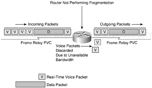
Because the average data frames are normally longer than the average voice frames, mixing both types of traffic on the same network could potentially cause network delays to the voice traffic and seriously jeopardize the voice quality. When the network is transmitting data frames, the longer data frames occupy an access link for a relatively longer period of time than voice frames. This could cause voice frames to be delayed behind the data frames while waiting for their turn for transmission onto the access link. Figure 16-1 illustrates this problem.
An important part of the end-to-end delay encountered by voice frames is because of the serialization delay. The serialization delay is defined as the time it takes to place the bits of an entire frame onto an interface.
The serialization delay is governed by the following formula:
serialization delay = frame size (in bits) / link bandwidth (in bits/sec)
For example, a 1500-byte frame takes approximately 214 ms to leave the router on a 56-kbps line. For voice traffic, the serialization delay ideally should not exceed 20 ms. A high serialization delay can cause delay and latency for voice traffic. Some form of network control needs to be used.
The Frame Relay Forum's standard for fragmenting large Frame Relay frames into smaller pieces is defined in the FRF.12 Implementation Agreement. The FRF.12 Implementation Agreement defines a fragmentation scheme for Frame Relay to support voice and other real-time or delay-sensitive data on low-speed Frame Relay links. The FRF.12 Implementation Agreement can be downloaded from the Frame Relay Forum public web site at this address: http://www.mplsforum.org/frame/Approved/FRF.12/frf12.pdf.
Two other fragmentation schemes are supported by the Cisco IOS software on Cisco devices. They are the Frame Relay Fragmentation using FRF.11 Annex C and the Cisco proprietary fragmentation. FRF.11 is the Frame Relay Forum's standard for supporting Voice over Frame Relay (VoFR). FRF.11 can be downloaded from the Frame Relay Forum public web site at this address: http://www.mplsforum.org/frame/Approved/FRF.11/frf_11.1.pdf.
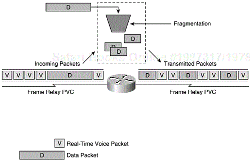
In general, Frame Relay Fragmentation supports the transport of mixed voice and data traffic across the same interface without the longer data frames causing excessive delay to the normally smaller-sized voice packets. On Frame Relay networks, fragmentation is especially beneficial on low-speed links where the serialization delay can be very high. The longer data frames are fragmented by the router into a sequence of shorter frames at the sending end. Eventually, the fragments are received and reassembled at the receiving end. By limiting the maximum frame size of the data packets, the fragmentation process allows the smaller fragmented data frames to be interleaved with the real-time delay-sensitive voice frames. This interleaving procedure is shown in Figure 16-2.
As illustrated in the diagram in Figure 16-2, using a fragmentation scheme in a mixed voice and data traffic environment allows network managers to control the size of the data frames and decreases the network latency experienced by delay-sensitive traffic. The longer data frames are segmented into a series of smaller fragments and are interleaved together with the similar-sized voice packets. Subsequently, the data fragments are reassembled at the receiving end. As a result, the wait time of the smaller voice packets is reduced, achieving the appropriate level of QoS required by real-time traffic.
This section discusses the few fragmentation schemes supported by Cisco. Cisco has developed three different methods of performing fragmentation with Frame Relay: FRF.12 Fragmentation, Frame Relay Fragmentation using FRF.11 Annex C, and the Cisco Proprietary Fragmentation. Each fragmentation scheme uses a different data format or encapsulation. Frame Relay frames are fragmented based on one of the three formats, depending on how the Frame Relay PVC was set up.
It is important to note that when Frame Relay End-to-End FRF.12 Fragmentation is configured, Weighted Fair Queuing (WFQ) or Low Latency Queuing (LLQ) is required. If Frame Relay End-to-End FRF.12 Fragmentation is configured in a Frame Relay map class, but the queuing type enabled is not WFQ or LLQ, the configured queuing type is automatically overridden by WFQ using the default values. WFQ for Frame Relay is configured with the frame-relay fair-queue map-class configuration command.
The following sections look at each supported fragmentation type.
The Cisco IOS software supports Frame Relay Fragmentation based on the Frame Relay Forum Implementation Agreement on Fragmentation FRF.12. FRF.12 defines standards for three types of Frame Relay Fragmentation: User-to-Network Interface (UNI), Network-to-Network Interface (NNI) and End-to-End between two Frame Relay DTE devices. The Frame Relay End-to-End FRF.12 Fragmentation feature is available in Cisco IOS Software Release 12.1(2)T or later.
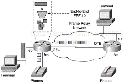
FRF.12 Fragmentation supports the transport of both real-time and non-real-time traffic across the same interface without causing excessive delay to the real-time traffic. An example of real-time traffic that is delay-sensitive is voice. FRF.12 is used to fragment the larger data frames into a sequence of shorter frames so that they can be interleaved with the real-time traffic for transmission. The fragmented data frames are reassembled at the receiving end.
Cisco supports End-to-End FRF.12 Fragmentation and FRF.12 Fragmentation on switched PVCs.
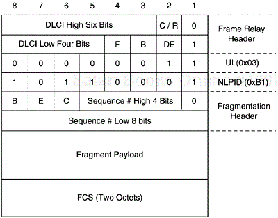
For End-to-End FRF.12 Fragmentation, a two-octet Frame Relay Fragmentation header follows the Frame Relay header (with multiprotocol encapsulations over Frame Relay options). A value of 0xB1 is specially assigned to the Network Layer Protocol ID (NLPID) field to identify the fragmentation header format. The data format for End-to-End FRF.12 Fragmentation is shown in Figure 16-3.
Within the fragmentation header, the B, E, and C bits represent beginning fragment, ending fragment, and control bit, respectively. The B bit is a 1-bit field that is set to the value of 1 when this is the first data fragment. For the remaining fragments from the same frame, this value is set to 0. The E bit is also a 1-bit field that is used to represent the last fragment of the frame. The E bit is set to the value of 1 for the last fragment and 0 for all other data fragments. If both the B and E bits are set to 1, this means that the fragment is the first and the last of the frame. The last C bit is set to 0 in all fragments, and it is reserved for future control functions.
The sequence number is a 12-bit binary number that is incremented for every data fragment transmitted on a virtual circuit (VC). The sequence number is used for reassembly after all fragments have been received.
End-to-End FRF.12 Fragmentation is configured on a per-PVC basis using a Frame Relay map class on a Cisco router. The frame-relay fragment fragment_size map-class configuration command sets up FRF.12 Fragmentation in the map class. The valid range for the fragment_size is from 16 to 1600 bytes, and the default value is 53 bytes. After configuring the Frame Relay map class, it can be applied to one or many PVCs to turn on FRF.12 Fragmentation. However, note that Frame Relay Traffic Shaping must be enabled at the main interface in order for Frame Relay Fragmentation to work. This is accomplished by configuring the frame-relay traffic-shaping command at the main interface level.
Figure 16-4 illustrates End-to-End FRF.12 Fragmentation between two peers in a Frame Relay network.
On Cisco routers configured as Frame Relay switches, the FRF.12 Fragmentation feature can be enabled on switched PVCs. Presently, only FRF.12 Fragmentation can be configured on switched PVCs on Cisco routers. Neither FRF.11 Annex C Fragmentation nor Cisco proprietary fragmentation are currently supported.
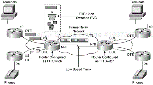
In a mixed voice and data network, Frame Relay access devices can transmit large data packets that can cause long serialization delays across low-speed trunks in switched Frame Relay networks. This problem is depicted in Figure 16-5.
There are many Frame Relay access devices that do not support the FRF.12 standard for End-to-End Fragmentation. An alternative is to perform the Frame Relay Fragmentation in the Frame Relay network. FRF.12 can be used between Frame Relay switches to reduce the serialization delay. This is shown in Figure 16-6.
As shown in Figure 16-6, when a Frame Relay switch (referred to as an edge router) receives large data frames that exceed the configured fragment size, it fragments those packets before transmitting them across the switched network. In most cases, the larger data frames are fragmented by the Frame Relay switch, while the voice frames that are smaller than the chosen fragment size pass through without fragmentation.
The edge router that receives the fragmented packets reassembles them before forwarding them to the Frame Relay access device that does not support FRF.12. However, if the Frame Relay access device supports FRF.12, the edge router forwards the fragmented packets to the Frame Relay access device without performing the reassembly. The destination Frame Relay access device itself reassembles the received fragmented packets. The configuration tasks and examples of FRF.12 fragmentation on switched PVCs is presented in the next section.
Figure 16-7 shows the data format of FRF.12 Fragmentation for switched PVCs.
Unlike the End-to-End Fragmentation format, the format illustrated in Figure 16-7 begins with a two-octet fragmentation header followed by the Frame Relay header. The function of the B, E, and C bits here is identical to that in the End-to-End Fragmentation format. These bits represent the beginning, end, and control bit, respectively. The use of the sequence number field is similar to that in the End-to-End Fragmentation format.
Comparing Figure 16-7 with the End-to-End Fragmentation format in Figure 16-3, observe the lowest order bit of the first octet is set to 1. This distinguishes the fragmentation header from the normal Frame Relay header. It also allows peers to detect misconfiguration, because both sides must agree on whether fragmentation is used or not. If an invalid frame is received, the frame is discarded.
To configure FRF.12 Fragmentation on switched PVCs, the switched keyword must be specified with the frame-relay fragment command on the routers configured as Frame Relay switches. The frame-relay fragment fragment_size switched map-class configuration command is used to enable FRF.12 Fragmentation on switched Frame Relay PVCs. The valid range for the fragment_size is from 16 to 1600 bytes, and the default value is 53 bytes. The map class is then applied to the switched Frame Relay PVC. Before this, Frame Relay Traffic Shaping must be enabled.
The conditions and restrictions on FRF.12 Fragmentation on switched PVCs are as follows:
Frame Relay Traffic Shaping must be enabled.
Interface queuing must be dual FIFO queuing or PVC interface priority queuing.
Switched PVCs must be configured with the connect command. The frame-relay route command will not work.
If the Frame Relay access device does not support FRF.12, no fragmentation occurs on the interface between the Frame Relay access device and the edge router. In this case, FRF.12 is performed on the interface between the edge router and the switched Frame Relay network.
If the Frame Relay access device is sending both voice and data on the same PVC, voice quality will suffer. This is because the edge router does not perform reordering of the packets on the switched PVCs. Send voice and data on separate PVCs.
Before Cisco IOS Release 12.1(5)T, Frame Relay Fragmentation could not be used together with hardware-assisted compression on a Cisco router. Frame Relay Fragmentation worked with software compression only. The added Frame Relay Fragmentation with hardware compression feature allows FRF.12, FRF.11 Annex C, and Cisco proprietary fragmentation to work with hardware compression. Both Cisco and IETF Frame Relay encapsulation types are supported.
The feature enables hardware compression to be used on Frame Relay networks that transmit voice and use fragmentation. Hardware compression has a higher performance compared with software compression. The hardware method offloads the CPU-intensive compression calculations from the CPUs of the routers, thereby freeing up CPU cycles for other processes.
In addition, the Frame Relay Fragmentation with hardware compression feature allows header compression (TCP/IP and RTP headers) to be used on the same VC or interface. Before this feature was added, it was not possible to configure both payload compression and header compression. The header compression schemes worked only with Cisco proprietary encapsulation, and hardware compression (FRF.9) worked only with IETF encapsulation.
This feature introduces a new proprietary hardware and software compression protocol called data-stream compression, which can be used on the same VC or interface as header compression. The new data-stream compression is functionally equivalent to FRF.9 compression, but Cisco proprietary encapsulation must be used. When either data-stream or FRF.9 compression is used, Frame Relay FRF.12, FRF.11 Annex C, or Cisco proprietary fragmentation can be configured. However, on IETF encapsulated PVCs or interfaces, FRF.9 (both hardware and software) works with fragmentation, but header compression is not possible. As such, the new data-stream compression method and Cisco encapsulation must be used if header compression is also required.
The Frame Relay Fragmentation with hardware compression feature provides compatibility between hardware and software compression. This allows one peer to use hardware compression while the remote peer is using software compression.
Table 16-1 shows that Frame Relay Fragmentation with hardware compression is supported on the following platforms and requires the corresponding hardware compression modules.
Two different Frame Relay commands can be used to configure hardware compression with fragmentation. If header compression (for example, TCP/IP header compression) is required, Cisco proprietary encapsulation must be used.
To configure hardware compression on a point-to-point Frame Relay subinterface, the frame-relay payload-compress data-stream stac configuration command is used. For a multipoint interface or subinterface, the frame-relay map protocol protocol-address dlci payload-compress data-stream stac configuration command can be used.
The following steps describe the configuration tasks required to enable hardware compression on a Cisco router. The configuration tasks begin in the global configuration mode.
Enter the interface configuration mode of the router for a Frame Relay physical interface, a multipoint logical subinterface, or a point-to-point logical subinterface.
On a multipoint interface, enable Frame Relay hardware compression with the frame-relay map protocol protocol-address dlci payload-compress hardware stac [hardware-options] interface configuration command.
On a point-to-point subinterface, enable Frame hardware compression with the frame-relay payload-compress hardware stac [hardware-options] interface configuration command.
(optional) Select the hardware options for Frame Relay hardware compression. The hardware-options keyword is part of the frame-relay payload-compress command shown in Step 2 and Step 3. The options available are csa keyword for using a compression service adaptor, or distributed keyword for enabling compression on a VIP2.
(optional) If Cisco encapsulation is used, it is possible to enable header compression using either frame-relay ip tcp header-compression [passive] for TCP/IP header compression or frame-relay ip rtp header-compression [passive] for RTP header compression.
NOTE
The Frame Relay compression features that encompass FRF.9 payload compression (software), TCP/IP header compression, and RTP header compression are explained in Chapter 15.
It is important to note that VoFR and Voice over IP (VoIP) packets are not payload compressed when Frame Relay Fragmentation is used.
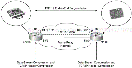
Example 16-1 and Example 16-2 show a configuration example of Frame Relay hardware compression and the resultant output of the show compress command, respectively. The hardware compression examples are based on the diagram in Figure 16-8.
Example 16-1. Configuration Example of Frame Relay Hardware
R1#show version
Cisco Internetwork Operating System Software
IOS (tm) 7200 Software (C7200-JS-M), Version 12.1(5)T10,  RELEASE SOFTWARE (fc2)
TAC Support: http://www.cisco.com/tac
Copyright  1986-2001 by cisco Systems, Inc.
Compiled Tue 07-Aug-01 18:02 by ccai
Image text-base: 0x60008960, data-base: 0x616F8000

ROM: System Bootstrap, Version 11.1(13)CA, EARLY DEPLOYMENT RELEASE SOFTWARE (fc1)
BOOTFLASH: 7200 Software (C7200-BOOT-M), Version 12.0(5), RELEASE SOFTWARE (fc1)

R1 uptime is 49 minutes
System returned to ROM by reload at 21:36:53 UTC Thu Apr 10 2003
System image file is "tftp://172.19.192.50/c7200-js-mz.121-5.T10"

cisco 7206 (NPE200) processor (revision B) with 114688K/16384K bytes of memory.
Processor board ID 6626210
R5000 CPU at 200Mhz, Implementation 35, Rev 2.1, 512KB L2 Cache
6 slot midplane, Version 1.3

Last reset from power-on
Bridging software.
X.25 software, Version 3.0.0.
SuperLAT software (copyright 1990 by Meridian Technology Corp).
TN3270 Emulation software.
Primary Rate ISDN software, Version 1.1.
8 Ethernet/IEEE 802.3 interface(s)
1 FastEthernet/IEEE 802.3 interface(s)
8 Serial network interface(s)
2 Channelized T1/PRI port(s)
1 Compression service adapter(s)
125K bytes of non-volatile configuration memory.
4096K bytes of packet SRAM memory.

4096K bytes of Flash internal SIMM (Sector size 256K).
Configuration register is 0x0


R1#show running-config
<output omitted>

interface Serial4/2
 no ip address
 encapsulation frame-relay
 frame-relay class fr_hwcomp
 frame-relay traffic-shaping
!
interface Serial4/2.102 point-to-point
 ip address 172.16.1.1 255.255.255.252
 frame-relay interface-dlci 102 CISCO
 frame-relay ip tcp header-compression
 frame-relay payload-compression data-stream stac
 !
map-class frame-relay fr_hwcomp
 frame-relay cir 128000
 no frame-relay adaptive-shaping
 frame-relay fair-queue
 frame-relay fragment 120
________________________________________________________________

R2#show running-config

<output omitted>

interface Serial1/0
 no ip address
 encapsulation frame-relay
 frame-relay class hw_comp
 frame-relay traffic-shaping
!
interface Serial1/0.201 point-to-point
 ip address 172.16.1.2 255.255.255.252
 frame-relay interface-dlci 201 CISCO
 frame-relay ip tcp header-compression
 frame-relay payload-compression data-stream stac
 !
map-class frame-relay hw_comp
 frame-relay cir 128000
 no frame-relay adaptive-shaping
 frame-relay fair-queue
 frame-relay fragment 120
Example 16-2. Compression Output of show compress Command from the Setup in Example 16-1
R1#ping
Protocol [ip]:
Target IP address: 172.16.1.2
Repeat count [5]: 20
Datagram size [100]: 500
Timeout in seconds [2]:
Extended commands [n]:
Sweep range of sizes [n]:
Type escape sequence to abort.
Sending 20, 500-byte ICMP Echos to 172.16.1.2, timeout is 2 seconds:
!!!!!!!!!!!!!!!!!!!!
Success rate is 100 percent (20/20), round-trip min/avg/max = 180/180/180 ms

R1#show compress
 Serial4/2 - DLCI: 102
     Hardware compression enabled
     CSA in slot 2 in use
     Compressed bytes sent:     11400 bytes   1 Kbits/sec  ratio: 0.884
     Compressed bytes recv:     10160 bytes   1 Kbits/sec  ratio: 0.000
     restarts: 27
last clearing of counters: 54 seconds
________________________________________________________________
R2#show compress
 Serial1/0 - DLCI: 201
     Hardware compression enabled
     CSA in slot 2 in use
     Compressed bytes sent:     11999 bytes   0 Kbits/sec  ratio: 0.883
     Compressed bytes recv:     10700 bytes   0 Kbits/sec  ratio: 0.000
     restarts: 27
last clearing of counters: 3456 seconds
________________________________________________________________
R1#show frame-relay ip tcp header-compression
DLCI 102        Link/Destination info: point-to-point dlci
  Interface Serial4/2:
    Rcvd:    0 total, 0 compressed, 0 errors
             0 dropped, 0 buffer copies, 0 buffer failures
    Sent:    0 total, 0 compressed,
             0 bytes saved, 0 bytes sent
    Connect: 256 rx slots, 256 tx slots,
             0 long searches, 0 misses 0 collisions
Figure 16-8. FRF.12 End-to-End Fragmentation and Hardware Compression Configured Between Two Peer Routers
As seen in Example 16-2, an extended ping is performed directly to router R2's interface from R1. This generates an ICMP traffic stream across DLCI 102, which is compressed by the hardware compression module on R1 using the data-stream compression method. At R2, the compressed packets are received. The show compress command indicates “Hardware compression enabled.” This implies that compression is now performed in the hardware compression module installed on the router. For example, on R1, this is performed on the Compression Service Adaptor (CSA) module installed in Slot 2.
Additionally, FRF.12 End-to-End Fragmentation is configured between routers R1 and R2. Observe that TCP/IP header compression is now enabled together with payload compression (via data-stream compression), and the Cisco encapsulation type must be used. The output of the show ip tcp header-compression command does not reveal that any active TCP/IP header compression took place because only ICMP packets were sent.
The Frame Relay Forum Implementation Agreement FRF.11 defines the standards for VoFR. The VoFR implementation uses FRF.11 to define how voice and data are encapsulated on a Frame Relay DLCI. On a Frame Relay DLCI that is configured to carry voice, all packets, including data, use the FRF.11 encapsulation. FRF.11 also supports a fragmentation scheme in FRF.11 Annex C.
FRF.11 Annex C defines the way data is carried on an FRF.11 DLCI configured for VoFR. A Frame Relay device supporting fragmentation using FRF.11 Annex C is able to distinguish real-time voice frames from the data frames. The FRF.11 payload indicates the specific traffic type. Thus, only frames with a data payload type are fragmented. The real-time voice frames bypass fragmentation regardless of the voice frame's size.
When VoFR (FRF.11) and fragmentation are both enabled on a Frame Relay PVC, the Frame Relay fragments are transmitted on the DLCI in the FRF.11 Annex C format. When FRF.11 is enabled on a PVC configured with fragmentation, all data packets use the FRF.11 Annex C format. As such, all data packets, including VoIP packets, contain the fragmentation headers, regardless of the size. For VoIP, FRF.11 Fragmentation is not recommended; FRF.12 Fragmentation is the preferred method. Figure 16-9 shows the FRF.11 Annex C format.
The use of the B, E, C bits and the sequence field are identical to those in the FRF.12 Fragmentation format.
The vofr Frame Relay DLCI configuration command is used to enable FRF.11 on a Frame Relay DLCI. It is also used to instruct the router to use FRF.11 Annex C format if fragmentation has been configured with the frame-relay fragment map-class configuration command. This feature is available in Cisco IOS Release 12.1(2)T or later.
Cisco supports a proprietary fragmentation format, which was implemented on the earlier releases of the Cisco MC3810 multiservice access concentrator platform. The Cisco proprietary form of fragmentation is used on data packets on a Frame Relay PVC that is also used for voice traffic. Cisco proprietary fragmentation is enabled with the vofr cisco DLCI configuration command. When the vofr cisco command is configured on a DLCI and fragmentation is enabled on a map class, the Cisco 2600, 3600, and 7200 series routers can interoperate as tandem nodes with Cisco MC3810 running Cisco IOS Releases before 12.0(3)XG or 12.0(4)T.
This section provides configuration examples of the Frame Relay Fragmentation features introduced in this chapter. The discussion in this section involves FRF.12 (both End-to-End and switched), FRF.11 Annex C, and Cisco proprietary fragmentation. The configuration tasks required to enable each type of fragmentation are introduced, in addition to the relevant IOS commands for monitoring and troubleshooting Frame Relay Fragmentation on Cisco devices.
Example 16-3 shows a typical configuration example of FRF.12 Fragmentation on switched PVCs. This configuration is based on the network depicted in Figure 16-10. In Figure 16-10, routers R2 and R3 are Cisco routers configured as Frame Relay switches on the edge of a switched Frame Relay network. In the earlier discussion about FRF.12 on switched PVCs, routers R2 and R3 were referred to as the edge routers. The Network-to-Network Interface (NNI) LMI is used between R2 and R3. Routers R1 and R4 represent Frame Relay access routers unable to support End-to-End FRF.12 Fragmentation.
In the future, remote LANs supporting real-time delay-sensitive applications will probably be joined to the Frame Relay network. To reduce serialization delay on the low-speed trunk between R2 and R3 in the switched Frame Relay network, FRF.12 Fragmentation is enabled on the switched PVCs between them. Frame fragmentation and reassembly takes place on routers R2 and R3.
Example 16-3. Configuration Examples of Routers in Figure 16-10
Router R1:

<output omitted>

ip routing
!
interface Serial1/1
 no ip address
 encapsulation frame-relay
!
interface Serial1/1.104 multipoint
 ip address 172.16.1.1 255.255.255.252
 frame-relay map ip 172.16.1.2 104 broadcast
________________________________________________________________
Router R2:

<output omitted>

frame-relay switching
!
interface Serial3/1
 no ip address
 encapsulation frame-relay
 clockrate 64000
 frame-relay interface-dlci 104 switched
 frame-relay intf-type dce
 !
interface Serial3/3
 no ip address
 encapsulation frame-relay
 clockrate 64000
 frame-relay traffic-shaping
 frame-relay interface-dlci 200 switched
  class fr_frag
 frame-relay intf-type nni
 !
map-class frame-relay fr_frag
 frame-relay cir 64000
 frame-relay bc 1000
 no frame-relay adaptive-shaping
 frame-relay fair-queue
 frame-relay fragment 100 switched
 !
connect FRF12 Serial3/1 104 Serial3/3 200
________________________________________________________________
Router R3:

<output omitted>

frame-relay switching
!
interface Serial2
 no ip address
 encapsulation frame-relay
 clockrate 64000
 frame-relay interface-dlci 401 switched
 frame-relay intf-type dce
 !
interface Serial3
 no ip address
 encapsulation frame-relay
 clockrate 64000
 frame-relay traffic-shaping
 frame-relay interface-dlci 200 switched
  class fr_frag
 frame-relay intf-type nni
 !
map-class frame-relay fr_frag
 frame-relay cir 64000
 frame-relay bc 1000
 no frame-relay adaptive-shaping
 frame-relay fair-queue
 frame-relay fragment 100 switched
 !
connect FRF12 Serial2 401 Serial3 200
________________________________________________________________
Router R4:

<output omitted>

ip routing
!
interface Serial1/0
 no ip address
 encapsulation frame-relay
!
interface Serial1/0.401 multipoint
 ip address 172.16.1.2 255.255.255.252
 frame-relay map ip 172.16.1.1 401 broadcast
After the routers are properly set and FRF.12 Fragmentation is configured, the show frame-relay fragment global EXEC command can be used to observe information regarding fragmentation on the router. Example 16-4 shows the output of the show frame-relay fragment command performed at R2.
Example 16-4. Output of the show frame-relay fragment Command at R2
R2#show frame-relay fragment
interface         dlci  frag-type    frag-size  in-frag    out-frag   dropped-frag
Serial3/3         200   end-to-end   100        0          0          0
The output of the show frame-relay fragment command indicates the type of fragmentation used on the specific DLCI. In this case, it shows that End-to-End FRF.12 Fragmentation is enabled on DLCI 200, though it doesn't indicate that FRF.12 is configured on a switched DLCI. “VoFR” in the “frag-type” field represents FRF.11 Annex C Fragmentation, whereas “VoFR-cisco” means Cisco proprietary fragmentation is used. The show frame-relay fragment command also shows the fragment size configured and the number of input, output, and dropped fragments. A large number of “dropped frag” is likely to be caused by a misconfiguration.
A more detailed version of the show frame-relay fragment command is available. The show frame-relay fragment interface type/number dlci command can be used to show additional fragmentation information besides the basic information. Example 16-5 shows the output of the more detailed version.
Example 16-5. Output of the show frame-relay fragment interface s3/3 200 Command at R2
R2#show frame-relay fragment interface Serial3/3 200

 fragment size 100                      fragment type end-to-end
 in fragmented pkts 20                  out fragmented pkts 20
 in fragmented bytes 1140               out fragmented bytes 1140
 in un-fragmented pkts 0                out un-fragmented pkts 0
 in un-fragmented bytes 0               out un-fragmented bytes 0
 in assembled pkts 10                   out pre-fragmented pkts 10
 in assembled bytes 1040                out pre-fragmented bytes 1040
 in dropped reassembling pkts 0         out dropped fragmenting pkts 0
 in timeouts 0
 in out-of-sequence fragments 0
 in fragments with unexpected B bit set 0
 in fragments with skipped sequence number 0
 out interleaved packets 0
If there are no errors encountered along the fragmentation path between the peers, some of the fragmentation information observed on the peers should match. For example, the total number of “in” and “out” fragmented packets between the peers should tally, as shown in the output of the show frame-relay fragment command performed on R2 and R3 in Example 16-6.
Example 16-6. Output of the show frame-relay fragment Command at R2 and R3 After Fragmentation Has Taken Place
R2#show frame-relay fragment interface Serial3/3 200

 fragment size 100                      fragment type end-to-end
 in fragmented pkts 20                  out fragmented pkts 20
 in fragmented bytes 1140               out fragmented bytes 1140
 in un-fragmented pkts 0                out un-fragmented pkts 0
 in un-fragmented bytes 0               out un-fragmented bytes 0
 in assembled pkts 10                   out pre-fragmented pkts 10
 in assembled bytes 1040                out pre-fragmented bytes 1040
 in dropped reassembling pkts 0         out dropped fragmenting pkts 0
 in timeouts 0
 in out-of-sequence fragments 0
 in fragments with unexpected B bit set 0
 in fragments with skipped sequence number 0
 out interleaved packets 0
________________________________________________________________
R3#show frame-relay fragment interface Serial3 200

 fragment size 100                      fragment type end-to-end
 in fragmented pkts 20                  out fragmented pkts 20
 in fragmented bytes 1140               out fragmented bytes 1140
 in un-fragmented pkts 0                out un-fragmented pkts 0
 in un-fragmented bytes 0               out un-fragmented bytes 0
 in assembled pkts 10                   out pre-fragmented pkts 10
 in assembled bytes 1040                out pre-fragmented bytes 1040
 in dropped reassembling pkts 0         out dropped fragmenting pkts 0
 in timeouts 0
 in out-of-sequence fragments 0
 in fragments with unexpected B bit set 0
 in fragments with skipped sequence number 0
 out interleaved packets 0
In the remaining examples, the network depicted in Figure 16-11 is used to verify End-to-End FRF.12, FRF.11 Annex C, and Cisco proprietary fragmentation on Cisco routers.
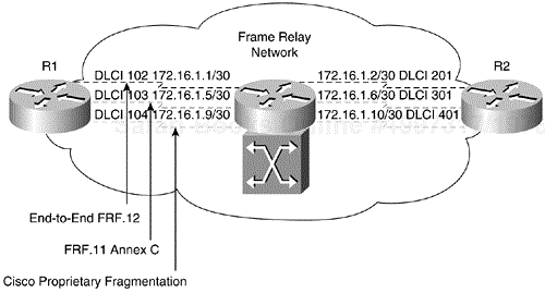
Figure 16-11. Network for Verifying End-to-End FRF.12, FRF.11 Annex C, and Cisco Proprietary Fragmentation
In Figure 16-11, routers R1 and R2 represent fragmentation peers at the edge of the Frame Relay network. Three DLCIs are configured at each end of the Frame Relay network, terminating at the routers. The three different fragmentation data formats—End-to-End FRF.12, FRF.11 Annex C, and Cisco proprietary fragmentation—are configured on a per-VC basis on each DLCI. Example 16-7 shows the configurations of routers R1 and R2 in Figure 16-11.
Example 16-7. Configurations of Routers R1 and R2 in Figure 16-11
Router R1:

<output omitted>

ip routing
!
interface Serial2/1
 no ip address
 encapsulation frame-relay
 frame-relay class fragment
 frame-relay traffic-shaping
!
interface Serial2/1.102 point-to-point
 ip address 172.16.1.1 255.255.255.252
 frame-relay interface-dlci 102
!
interface Serial2/1.103 point-to-point
 ip address 172.16.1.5 255.255.255.252
 frame-relay interface-dlci 103
  vofr data 4 call-control 5
!
interface Serial2/1.104 point-to-point
 ip address 172.16.1.9 255.255.255.252
 frame-relay interface-dlci 104
vofr cisco
!
map-class frame-relay fragment
 frame-relay cir 64000
 no frame-relay adaptive-shaping
 frame-relay fair-queue
 frame-relay voice bandwidth 16000
 frame-relay fragment 100
________________________________________________________________
Router R2:

<output omitted>

ip routing
!
interface Serial3/1
 no ip address
 encapsulation frame-relay
 frame-relay class fragment
 frame-relay traffic-shaping
!
interface Serial3/1.201 point-to-point
 ip address 172.16.1.2 255.255.255.252
 frame-relay interface-dlci 201
!
interface Serial3/1.301 point-to-point
 ip address 172.16.1.6 255.255.255.252
 frame-relay interface-dlci 301
  vofr data 4 call-control 5
!
interface Serial3/1.401 point-to-point
 ip address 172.16.1.10 255.255.255.252
 frame-relay interface-dlci 401
  vofr cisco
!
map-class frame-relay fragment
 frame-relay cir 64000
 no frame-relay adaptive-shaping
 frame-relay fair-queue
 frame-relay voice bandwidth 16000
 frame-relay fragment 100
When Frame Relay Fragmentation is configured with the frame-relay fragment command under the Frame Relay map-class and the map-class is assigned to a Frame Relay DLCI, FRF.12 Fragmentation is the default fragmentation scheme enabled.
NOTE
When a Frame Relay map class is assigned to the physical interface with the frame-relay class map-class-name command, the same map class is inherited by all subinterfaces on the main interface. The more specific class map-class-name DLCI configuration command can be used to assign a particular Frame Relay map class to a DLCI.
Referring to Example 16-7, End-to-End FRF.12 Fragmentation is enabled on DLCI 102 at router R1 and on DLCI 201 at router R2 with the frame-relay fragment map-class configuration command. On DLCI 103 at router R1 and on DLCI 301 at router R2, the vofr command is used to enable VoFR on a specific DLCI and to configure specific subchannels on that DLCI. The data keyword specifies the subchannel to use for data. The call-control keyword specifies the subchannel to be used for call-control signaling. When the Frame Relay Fragmentation configurations are already present on the DLCI, FRF.11 Annex C Fragmentation is immediately used after VoFR is configured on the DLCI.
Finally, on DLCI 104 at router R1 and on DLCI 401 at router R2, the vofr cisco DLCI configuration command is used to turn on the Cisco proprietary fragmentation on this specific DLCI.
The show frame-relay vofr global EXEC command can be used to display Frame Relay VoFR statistics on the router. Example 16-8 shows an output of the show frame-relay vofr command at R1.
Example 16-8. Output of show frame-relay vofr Command at R1
R1#show frame-relay vofr

interface         vofr-type   dlci   cid   cid-type
Serial2/1.104     VoFR cisco  104    4     data
Serial2/1.104     VoFR cisco  104    5     voice call-control
Serial2/1.103     VoFR        103    4     data
Serial2/1.103     VoFR        103    5     voice call-control
This command displays the information about the FRF.11 subchannels being used on VoFR DLCIs. The vofr-type field indicates the type of VoFR DLCI being observed. The cid-type represents the type of traffic carried on the corresponding subchannel.
The configured fragment size in the Frame Relay map class is 100 bytes. As such, any outgoing packets on the DLCIs with a size greater than 100 bytes are subjected to fragmentation. In the next example, extended pings to router R2 are performed at R1. This is shown in Example 16-9.
Example 16-9. Illustrating Fragmentation Occurring at R1
R1#ping
Protocol [ip]:
Target IP address: 172.16.1.2
Repeat count [5]: 10
Datagram size [100]: 500
Timeout in seconds [2]:
Extended commands [n]:
Sweep range of sizes [n]:
Type escape sequence to abort.
Sending 10, 500-byte ICMP Echos to 172.16.1.2, timeout is 2 seconds:
!!!!!!!!!!
Success rate is 100 percent (10/10), round-trip min/avg/max = 172/173/176 ms

R1#ping
Protocol [ip]:
Target IP address: 172.16.1.6
Repeat count [5]: 10
Datagram size [100]: 500
Timeout in seconds [2]:
Extended commands [n]:
Sweep range of sizes [n]:
Type escape sequence to abort.
Sending 10, 500-byte ICMP Echos to 172.16.1.6, timeout is 2 seconds:
!!!!!!!!!!
Success rate is 100 percent (10/10), round-trip min/avg/max = 172/172/172 ms

R1#ping
Protocol [ip]:
Target IP address: 172.16.1.10
Repeat count [5]: 10
Datagram size [100]: 500
Timeout in seconds [2]:
Extended commands [n]:
Sweep range of sizes [n]:
Type escape sequence to abort.
Sending 10, 500-byte ICMP Echos to 172.16.1.10, timeout is 2 seconds:
!!!!!!!!!!
Success rate is 100 percent (10/10), round-trip min/avg/max = 172/172/172 ms

R1#show frame-relay fragment
interface         dlci  frag-type    frag-size  in-frag    out-frag   dropped-frag
Serial2/1.102     102   end-to-end   100        68         68         0
Serial2/1.103     103   VoFR         100        68         68         0
Serial2/1.104     104   VoFR-cisco   100        68         68         0
________________________________________________________________
R2#show frame-relay fragment
interface         dlci  frag-type    frag-size  in-frag    out-frag   dropped-frag
Serial3/1.201     201   end-to-end   100        68         68         0
Serial3/1.301     301   VoFR         100        68         68         0
Serial3/1.401     401   VoFR-cisco   100        68         68         0
The show frame-relay fragment command indicates the type of fragmentation scheme enabled on each specific Frame Relay DLCI configured on the router.
A common cause of problems or poor performance related to the use of Frame Relay Fragmentation is due to users' misconfigurations. It is important to ensure that the same fragmentation scheme is used between two peers. For example, fragmentation fails if one peer is configured with FRF.12 Fragmentation while the other side is using FRF.11 Annex C Fragmentation. When configuring routers for Frame Relay Fragmentation, always use the same fragmentation scheme between them. In addition, recall that WFQ and LLQ are the only queuing strategies that can be used with fragmentation. Fragmentation will not work if other queuing schemes are employed.
It is also imperative to use a carefully chosen fragment size when configuring fragmentation. For example, poor performance can occur if the fragment size is too small and real-time voice packets are getting fragmented. FRF.12 fragments voice packets if the fragmentation size is set to a value smaller than the voice packet size. If your application supports VoFR, FRF.11 Annex C would be better because it does not fragment voice packets, regardless of the configured fragment size.
This chapter discussed the use of fragmentation on Frame Relay networks to manage latency and delay for real-time multiservice traffic, such as voice. Frame Relay Fragmentation has brought many benefits to integrated voice and data Frame Relay networks. This chapter explained serialization delay on low-speed networks and how fragmentation can be used to reduce this delay.
This chapter introduced Cisco's implementations of Frame Relay Fragmentations on Cisco routers. The three different types of Frame Relay Fragmentation schemes supported by Cisco routers include FRF.12 Fragmentation (both End-to-End and switched), Frame Relay Fragmentation with FRF.11 Annex C, and Cisco proprietary Frame Relay Fragmentation.
This chapter also covered the Cisco IOS configuration tasks for each Frame Relay Fragmentation scheme supported on Cisco routers. It explained the Cisco IOS show commands for monitoring and maintaining Frame Relay Fragmentation configurations. The most common issues and probable causes of problems arising from the use of fragmentation were mentioned. The chapter wraps up with a case study scenario. The case study illustrates a common problem encountered by a typical Frame Relay customer attempting to support voice and data traffic on the same network. Frame Relay Fragmentation can be used to effectively deal with such issues.
In Part IV, a general overview of Frame Relay queuing mechanisms is presented. The next chapter contains a detailed discussion on Frame Relay Congestion Management features.
Frame Relay Forum Implementation Agreement FRF.12: Frame Relay Fragmentation, edited by Andrew G. Malis, 1997: http://www.mplsforum.org/frame/Approved/FRF.12/frf12.pdf
Frame Relay Forum Implementation Agreement FRF.11: Voice over Frame Relay, edited by Ted Hatala, Ross Kocen, Kenneth Rehbehn, Tim Chui, 1999: http://www.mplsforum.org/frame/Approved/FRF.11/frf_11.1.pdf
Cisco IOS 12.1(2)T Release FRF.12 Support: http://www.cisco.com/univercd/cc/td/doc/product/software/ios121/121newft/121t/121t2/dtfr12ap.htm
Cisco IOS 12.1(2)T Release FRF.12 Support on Switched PVCs: http://www.cisco.com/univercd/cc/td/doc/product/software/ios121/121newft/121t/121t2/dtfragsw.htm
Cisco IOS 12.1(5)T Release Frame Relay Fragmentation with Hardware Compression: http://www.cisco.com/univercd/cc/td/doc/product/software/ios121/121newft/121t/121t5/dtfrfwhc.htm
Cisco IOS 12.2 Release WAN Configuration Guide: http://www.cisco.com/univercd/cc/td/doc/product/software/ios122/122cgcr/fwan_c/wcffrely.htm#1070622
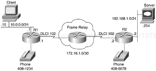
In this section, a scenario depicting a typical mixed voice and data environment demonstrates how Frame Relay Fragmentation can be used to improve the performance of the network. This case study is based on the diagram shown in Figure 16-12.
A customer of XYZ Frame Relay service provider has complained of bad voice quality after attempting to use the existing 128-kbps Frame Relay connection for VoIP services. The customer is interested in keeping the converged data and voice Frame Relay network and does not want a separate network for voice services, in order to curb phone toll charges. To save on cost, the customer does not wish to purchase additional bandwidth and wants to explore other solutions to improve performance.
After investigations by the network manager, the bad voice quality problem is determined to be primarily the result of long file transfer taking place between the ERP clients and the servers. Voice packets are getting blocked behind the large data packets, resulting in jitters in the VoIP conversation. The transmission of large data packets over the link is causing increased serialization delay for the smaller voice packets.
This example shows how Frame Relay Fragmentation using FRF.12 can be used to improve the overall performance. Example 16-10 shows the configurations of routers R1 and R2 after implementing Frame Relay Fragmentation.
Example 16-10. Configurations of Routers in Case Study Scenario
Router R1:

<output omitted>

ip routing
!
interface Ethernet2/0
 ip address 10.0.0.1 255.255.255.0
 !
interface Serial1/0
 no ip address
 encapsulation frame-relay
 frame-relay traffic-shaping
!
interface Serial1/0.102 point-to-point
 ip address 172.16.1.1 255.255.255.252
 frame-relay interface-dlci 102
   class voip
   !
map-class frame-relay voip
 frame-relay cir 128000
 no frame-relay adaptive-shaping
 frame-relay fair-queue
 frame-relay ip rtp priority 16383 16384 128
 frame-relay fragment 200
 !
dial-peer voice 1 pots
 destination-pattern 4081234
 port 0/0
!
dial-peer voice 2 voip
 destination-pattern 4085678
 session target ipv4:172.16.1.2
________________________________________________________________
Router R2:

<output omitted>

ip routing
!
interface Ethernet2/0
 ip address 192.168.1.2 255.255.255.0
 !
interface Serial1/1
 no ip address
 encapsulation frame-relay
 frame-relay traffic-shaping
!
interface Serial1/1.201 point-to-point
 ip address 172.16.1.2 255.255.255.252
 frame-relay interface-dlci 201
   class voip
   !
map-class frame-relay voip
 frame-relay cir 128000
 no frame-relay adaptive-shaping
 frame-relay fair-queue
 frame-relay ip rtp priority 16383 16384 128
 frame-relay fragment 200
!
dial-peer voice 1 pots
 destination-pattern 4085678
 port 0/0
!
dial-peer voice 2 voip
 destination-pattern 4081234
 session target ipv4:172.16.1.1
After implementing FRF.12 on the routers, XYZ's customer has noticed dramatic improvement in terms of the voice quality. Moreover, the customer is also assured that fragmentation did not result in any substantial delay or other negative effects on its ERP applications.
In addition to FRF.12, Frame Relay IP RTP priority is configured to ensure that voice traffic matching the specified UDP port ranges is reserved a bandwidth of 128 kbps. Other advanced Frame Relay QoS features, such as Compressed RTP (cRTP), IP Precedence marking, and WFQ, are also suitable for use on this network. For instance, cRTP can be used to reduce the size of voice packets traveling across the network, and IP Precedence marking can be used to prioritize the ERP traffic over users' other normal traffic.
