Network designers and implementers often find themselves with the compelling task of selecting the most appropriate network devices for WAN connectivity. The selection criteria usually involve a number of factors, such as bandwidth requirements, equipment cost, and scalability options. The first section of this chapter will consider the typical networking devices, serial interfaces, and the common cabling standards used in a general Frame Relay network. Then the chapter will take a look at Cisco's wide range of router product lines and wide-area switches that offer a complete end-to-end solution to customers. Later in the chapter, Cisco's implementation of the Frame Relay technology will be discussed.
The topics and questions that this chapter addresses include the following:
Physical network devices used in a Frame Relay network and the definition of DTE and DCE devices
Cisco serial interfaces for supporting a Frame Relay network and the most popular industry serial cabling standards
The most popular Cisco router platforms used in Frame Relay environments
Introduction to Cisco's implementation of Frame Relay, which includes the LMIs and Frame Relay encapsulations supported
Introduction to static and dynamic Inverse ARP DLCI to network address mapping
After completing this chapter, readers will be able to recognize the common devices, interfaces, and cabling used in a Frame Relay network. You will also be able to identify the most suitable Cisco router product or wide-area switches for a Frame Relay network. Finally, you will have a basic understanding of Cisco's implementation of Frame Relay.
In general, the physical network devices in a Frame Relay network belong to two broad categories:
Data terminal equipment (DTE)
Data circuit-terminating equipment (DCE)
A DTE device is typically the end device of a network. It is usually classified as customer premises equipment (CPE) if it is physically located at the customer's site. A router can be owned by a customer or leased directly from the Frame Relay network carrier. It can be defined as CPE, which functions as a DTE device. Other examples of DTE devices include terminals, computers, or servers.
A DCE device supplies clocking signals and provides synchronization functions to a connected DTE device. Some DCE devices provide switching functions and services to transmit frames through a Frame Relay network. A Frame Relay switch is an example of such a DCE device. A Cisco router can be configured as a Frame Relay switch. Table 2-1 categorizes the general DTE and DCE devices.
Table 2-1. Examples of DTE and DCE Devices
DTE Devices | DCE Devices |
|---|---|
Personal computers | CSU/DSU |
Routers (can also be DCEs) | Hub |
Servers | Modem |
Terminals | Multiplexors |
Switches |
Figure 2-1 illustrates the relationship between DTE and DCE devices in a Frame Relay network.
A channel services unit/data services unit (CSU/DSU) is a DCE device often found in a Frame Relay network. In the United States and many other countries, a CSU/DSU device provides an interface to the telephone company or to the carrier offering Frame Relay services. A CSU/DSU device provides clocking and synchronization functions to a connected Cisco router. In this arrangement, the CSU/DSU is the DCE device and the Cisco router acts as the DTE device. Typically, the Cisco router is connected to the CSU/DSU device on a synchronous serial interface, and in turn, the CSU/DSU is directly attached to a Frame Relay switch in the carrier's network. The Frame Relay access link between the CSU/DSU and the Frame Relay switch can be a 64 kbps leased line or a T1 circuit connected on coaxial cables. It can also use any other industry standard; it is largely dependent on the carrier's implementation.
Note that in Figure 2-1, the Cisco router is connected directly to the Frame Relay switch without connecting to an external CSU/DSU device. This is possible because Cisco offers cost-effective WAN interface cards with an integrated CSU/DSU. Such integrated interface cards provide internal clocking and signaling so the router does not need an external CSU/DSU. Figures 2-2 and 2-3 illustrate a common example whereby a Cisco router is connected to an external CSU/DSU on a synchronous serial interface. The CSU/DSU then connects directly to the Frame Relay switch in the carrier's network on a T1 link.
NOTE
You can identify whether a Cisco router is acting as a DTE or a DCE device to a connected network by examining the serial cable attached to its synchronous serial interface or by the show controllers serialcommand. If a DTE male serial cable is connected to an interface, the Cisco router acts as a DTE device to the network connected on that serial interface. Likewise, if a DCE female serial cable is connected to a serial interface, the interface acts as DCE device that supplies clocking signals to a connected DTE. An interesting point to note is that a Cisco router can act as a DCE on its DTE interface connected to a Frame Relay network by enabling frame-relay switchingglobally and configuring frame-relay intf-type dceon the interface.
A synchronous serial interface is usually used to connect a Cisco router to a Frame Relay network. Cisco routers support a wide range of synchronous serial interface cards that conform to present industry communication standards. Refer to the Cisco's product guide for an up-to-date and complete range of supported serial synchronous interfaces.
On a Frame Relay network, the most commonly used industry communication standards are provided by the Electronic Industries Alliance (EIA) (http://www.eia.org) and the Telecommunications Industry Association (TIA) (http://www.tiaonline.org). Today, the EIA is a national trade organization that comprises more than 80% of the electronics industry and includes major U.S. manufacturers. The TIA represents the communication sector of the EIA. Last but not least, the International Telecommunication Union (ITU-T) (http://www.itu.int/ITU-T/) is responsible for the development of the popular X.21 and V.35 industry communication standards. The ITU-T is an international organization where governments and private sectors coordinate global telecommunication networks and services. The full titles of the mentioned popular industry communication standards currently used in most Frame Relay environments are provided in the following list:
TIA/EIA–232—. Interface between Data Terminal Equipment (DTE) and Data Circuit-terminating Equipment (DCE) employing serial binary data interchange.
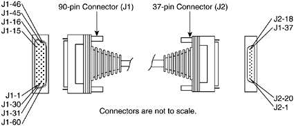
TIA/EIA– 449—. 37-Position and 9-Position interface for DTE and DCE.
TIA–530—. High Speed 25-Position interface for DTE and DCE, including Alternative 26-Position Connector.
ITU-T V.35—. Data transmission at 48 kbits/s using 60-108 Khz group band circuits.
ITU-T X.21—. Interface between DTE and DCE for synchronous operation on public data networks.
NOTE
To obtain the commercial versions of the industry communication standards discussed in this section, readers can go to the TIA public website at: http://www.tiaonline.org/standards/search_n_order.cfm. Similarly, the ITU-T standards can be obtained from ITU-T public website at: http://www.itu.int/publications/main_publ/itut.html.
TIA/EIA-232 was formerly known as RS-232. TIA/EIA-232 uses 25 pins on the interface. It is a common physical layer interface standard developed by EIA and TIA that supports unbalanced circuits at signal speeds of up to 64 kbps. Figure 2-4 illustrates the TIA/EIA-232 cable assembly.
TIA/EIA-449 was formerly known as RS-449. TIA/EIA-449 uses 37 pins on the interface. It is another popular physical layer interface standard developed by EIA and TIA that supports faster signal speeds of up to 2 Mbps and also longer cable runs. Figure 2-5 shows the TIA/EIA-449 cable assembly.
The TIA-530 standards support balanced circuits at higher speed and greater distance compared with the TIA/EIA-440 standards. TIA-530 has 25 pins on the interface and uses a DB-25 connector, both similar to TIA/EIA-232. TIA-530 supports a maximum transmission speed of 2 Mbps, and a faster speed at 4 Mbps can be achieved over shorter distances. Figure 2-6 shows the cable assembly of TIA-530.
V.35 is an ITU-T standard describing a synchronous physical layer protocol used for communications between a network access device and a packet network. V.35 uses 34 pins on the interface and is most commonly used in the United States and in Europe. V.35 is recommended for speeds up to 48 kbps. Figure 2-7 shows the ITU-T V.35 cable assembly.
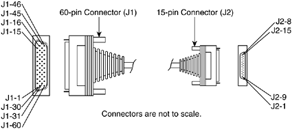
X.21 uses 15 pins on the interface. It is an ITU-T standard for serial communications over synchronous digital lines commonly used in Europe and Japan. Figure 2-8 illustrates the ITU-T X.21 cable assembly.
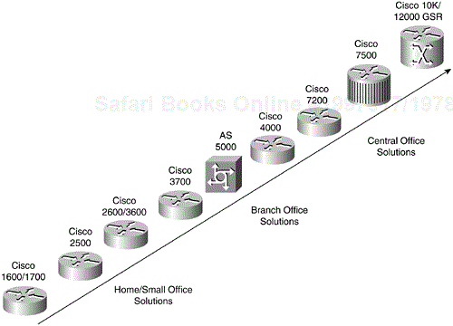
In 1990, Cisco Systems released its first product to support Frame Relay technology. Presently, the feature-rich Cisco IOS software supports Frame Relay on almost every family of the router product line. Cisco has a very wide range of router products to meet different users' requirements. Each Cisco router family considered in Figure 2-9 has better performance, higher memory capacities, higher port densities, and faster interface speeds as you move up the chart. Each of these families is described in greater detail in the sections that follow.
The Cisco 1600/1700 and 2600 series routers are modular platforms that support low-speed WAN Interface Cards and built-in 10/100 Ethernet connections for home and small office users. The 2500 series routers are fixed configuration routers, but some models do support WAN connectivity. It is not possible to add or change existing modules or interfaces on a 2500 series router. Presently, the very popular 2500 series has been largely replaced by the newer 2600 and 3700 series routers. Basically, the 1600/1700/2500/2600 series routers are for homes and small offices and can support a range of synchronous serial interfaces to provide connectivity to a Frame Relay network. In addition, the c1700 and c2600 series routers support voice interface cards (VIC) for voice applications.
The Cisco 3600/4000 and AS5000 series routers are modular routers that run on more powerful and faster Reduced Instruction Set Computer (RISC) processors. These platforms have greater memory capacity for higher performance than their home/small office counterparts. Similar to the c2500 series, the c4000 series router has reached its end-of-sales. The c3600 and AS5000 series support higher port densities; these platforms are ideal for branch office connectivity. The c3600 series also supports voice modules for voice applications.
The new Cisco 3700 series routers provide port density to branch offices in a compact form factor. The c3700 series offers high levels of application and service integration at a lower cost.
The Cisco 7200/7500 series and 12000 GSR series routers are powerful, high-performance routers designed for central office connectivity. These platforms are commonly used when service providers need high port densities and fast interface processing speeds. The 10000 Series Internet routers offer aggregation services at the network edge and are designed for 99.999 percent high availability (HA). The 12000 GSR series Internet routers are the first in a product class of gigabit switch routers which offers high-speed OC-192 Packet over Sonet (POS) line cards at full 10 Gbps (Gigabits per second) line rate.
Cisco offers a range of carrier-class wide-area switches. These switches provide an end-to-end network solution that is tightly integrated with Cisco router and access products for enterprises and service provider customers. The Cisco BPX, IGX, and MGX series multiservice switches allow customers to deploy a scalable network to cost-effectively deliver Frame Relay, voice/video, or Asynchronous Transfer Mode (ATM) broadband services with end-to-end high quality of service. BPX, IGX, and MGX topics are covered extensively in the Cisco Press title: Cisco WAN Switching Professional Reference by Tracy Thorpe (ISBN: 1587050552, May 2002).
The maximum possible transmission speed on an access link largely depends on the Frame Relay network carrier's implementation and the type of transmission facility it uses and supports. Cisco devices can support Frame Relay at DS-3 access speeds of 45 Mbps. In most countries, Frame Relay network carriers or service providers offer Frame Relay services with a base CIR to their customers. In the context of a typical small-scale organization, a Frame Relay connection service with a CIR of between 128 kbps to 1.544 Mbps (T1) can normally allow an organization to support a standard network traffic load for common applications such as Telnet, e-mail, FTP, and HTTP.
When oversubscription occurs, small increments of 4 kbps to 64 kbps can usually be added to the subscribed CIR. In this scenario, selecting a modular access router from the small office category to connect to the service provider is a reasonably good choice. Investing in a more powerful branch office router with a faster interface card can cater to future growth and expansion in the long run. In general, the router selection criterion for WAN connectivity is normally a scalable solution that can meet bandwidth requirements while keeping costs under control.
Cisco's Frame Relay implementation supports the basic Frame Relay protocol and conforms with the local management interface (LMI) specifications originally developed by the consortium of Cisco Systems, StrataCom, Northern Telecom, and Digital Equipment Corporation (DEC). This consortium of the four companies is popularly known as the “Gang of Four.” One of the main objectives of the collaboration by the Gang of Four was to enhance the interoperability of future Frame Relay products and cooperation among different vendors. The developed set of LMI enhancements helps to reduce the complexity of managing and supporting large internetworks.
One of the LMI enhancements Cisco supports is LMI status message exchange. LMI status message exchange allows a DTE device to communicate and synchronize with a DCE device in a Frame Relay network. The Cisco IOS supports three different LMI types: Cisco, ANSI Annex D, and Q.933-A Annex A. The Cisco LMI is defined jointly by Cisco and the Gang of Four. ANSI Annex D is defined by the ANSI TI.617 standards. ANSI Annex D is commonly used in many Frame Relay networks. Q.933-A Annex A is accredited by ITU-T. All three LMI types exchange status messages on globally reserved DLCIs. Both ANSI Annex D and Q.933-A Annex A LMI types use DLCI 0 for message exchange, whereas the Cisco LMI type listens to status messages on DLCI 1023. Both DLCI 0 and DLCI 1023 are globally reserved DLCIs and may not be reused for addressing other virtual circuits in a Frame Relay network.
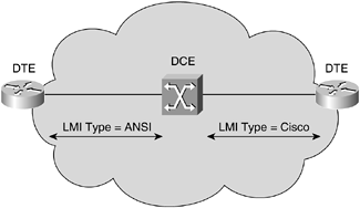
In a Frame Relay network, LMI messages are exchanged between the Frame Relay switch and its connected DTE device, usually a router. Each of the supported LMI types has a different implementation and is thus incompatible with the others. For this reason, the LMI types configured on both ends of the Frame Relay access link between a DCE and a DTE device must be identical. Figure 2-10 further illustrates this concept. Table 2-2 shows the supported LMI type and the DLCI in use.
Table 2-2. Cisco-Supported LMI Type and the DLCI in Use
Supported LMI Type | DLCI | Developing Organization |
|---|---|---|
Cisco | 1023 | Gang of Four |
ANSI Annex D | 0 | ANSI TI.617 |
Q933A Annex A | 0 | ITU-T (CCITT) |
As of Cisco IOS Software Release 11.2, IOS supports the LMI Autosense feature. This feature allows the Cisco router to automatically detect the LMI type supported by the connected Frame Relay switch. When an LMI type is not explicitly configured on a Cisco router, LMI autosense is activated. When LMI autosense is running, the router sends out full status request messages for each of the supported LMI types—ANSI, Q.933-A, and Cisco, in that order—on DLCI 0 or DLCI 1023. Eventually, the router receives a status reply message from the Frame Relay switch and detects the LMI type used by the switch. The router automatically configures itself to select the LMI type supported by the switch. When an LMI type is explicitly configured on the router, the LMI Autosense feature is overridden and the router uses the configured LMI type instead.
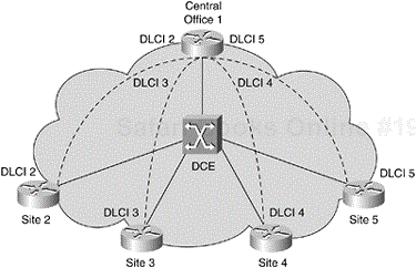
The LMI global addressing extension allows the Frame Relay DLCI to have a global significance rather than a local significance. The idea of global significance assigns an unique DLCI address to each Frame Relay DTE in the network, much the same way that IP addresses or MAC addresses are used to uniquely identify a device on the Internet or a LAN. To best describe the concept of global significance in a Frame Relay network, refer to the example in Figure 2-11.
In Figure 2-11, a hub-and-spoke topology connects four remote sites to a central office. Four PVCs are provisioned at the central office to allow it to connect to each of its remote sites. In this Frame Relay network, the four PVCs at the central office are statistically multiplexed onto a single physical access link connected to the Frame Relay switch. In this example, the central office router uses DLCI 2, 3, 4, and 5 to distinguish each PVC connection to its remote sites 2, 3, 4, and 5, respectively. Similarly, each remote site router uses the same DLCI on its end of the PVC to the central office. This DLCI addressing scheme works because Frame Relay allows local significance, and the same DLCI can be reused at both ends of a PVC. However, if more than one PVC exists at a local end, a different DLCI must be used to reference and distinguish between them. In this example, the router at site 2 uses DLCI 2 to send traffic to the central office router. Likewise, the central router uses the same DLCI 2 to send traffic back to the router at site 2, but it uses DLCI 3 to reach the users at site 3. Now consider Figure 2-12 where the same network is revisited, but this time using a global addressing scheme.
Using global addressing, each Frame Relay DTE is uniquely addressed in a Frame Relay network, the same way that an end station is addressed uniquely with its MAC address on a LAN. This allows all Frame Relay DTEs to send traffic to a remote destination using a globally unique DLCI value assigned to that destination. For example, all the remote sites now use DLCI 1 to reach the central office because the central office is identified with the globally unique DLCI 1. In other words, DLCI 1 leads to the central office. Similarly, the central router recognizes that DLCI 2 leads to remote site 2, DLCI 3 leads to remote site 3, and so on. Note that a DLCI address is not reused anywhere in the Frame Relay network, and each Frame Relay DTE has a uniquely defined DLCI address that distinguishes it from its peer DTEs.
Global addressing allows each Frame Relay DTE to be identified as an unique end station in the Frame Relay network. It is worth mentioning that there is a restriction to using global addressing in any Frame Relay network. For global addressing to work, the total number of Frame Relay DTEs in the network must not exceed the allowed range of DLCI values in the header. In order to apply the global addressing scheme, each Frame Relay DTE in the network has to be assigned a unique DLCI address. This leads to the question of how many DLCIs carrying users' data can be assigned in a Frame Relay network. The DLCI is a 10-bit address, which gives us about 1024 DLCIs. However, there are some DLCIs that are reserved for sending LMI messages and multicasting. As such, when using Cisco LMI, the range of allowed DLCIs for users' data is 16 to 1007. The ANSI Annex D and ITU Q.933-A support a range from 16 to 992.
The other issue is with the number of DLCIs that can be configured on a physical interface in the Cisco router. The LMI protocol specifies that all PVC status reports have to fit into a packet. How many of these can be squeezed into a packet depends on the maximum transmission unit (MTU) of the physical interface. The formula for calculating the maximum number of DLCI per physical interface is (MTU – 20)/5, where MTU is in bytes. The default MTU size of an interface on a Cisco router is 1500 bytes; the interface can have a maximum of 296 DLCIs.
The standard Frame Relay header and trailer defined by Q.922-A do not have a facility to allow multiprotocol to be transported over Frame Relay. All protocols are encapsulated inside the basic Frame Relay frame, but there is no field in the basic header that allows Frame Relay DTEs to identify the protocol carried within and correctly process the packet.
There are two solutions to this problem: Cisco proprietary encapsulation and RFC 1490. Cisco supports both implementations. Both solutions allow multiprotocol to be transported over Frame Relay. In both methods, an additional Protocol Type or Protocol ID field is inserted inside the frame behind the basic Q.922-A headers to identify the transported protocol.
Consider Figure 2-13 for the Cisco and RFC 1490 encapsulated frames.
The first solution, using Cisco encapsulation developed by Cisco and three other vendors, defines an additional header inside the basic Q.922-A Frame Relay headers. The additional header has a 2-byte Protocol Type ID field to identify the protocol carried inside the frame. The Cisco encapsulation is the default encapsulation on all Cisco routers.
The second encapsulation option supported is defined in RFC 1490 “Multiprotocol over Frame Relay,” which includes routed and bridged frame options. RFC 1490 can be found at http://www.faqs.org/rfcs/rfc1490.html. An NLPID field in the Frame Relay header identifies the different network layer protocol carried inside the Frame Relay frame. For example, a NLPID field with a value of 0xCC indicates an IP packet carried by the Frame Relay frame. A NLPID field with a value of 0x00 means an invalid packet is in the Frame Relay frame.
The Frame Relay encapsulation type used by the peer Frame Relay DTE devices at both ends of a Frame Relay virtual circuit must be identical. This is because Frame Relay frames travel end-to-end over the Frame Relay virtual circuit from the near-end Frame Relay DTE device to the far-end Frame Relay DTE device. A Frame Relay router is an example of a Frame Relay DTE device. The Cisco Frame Relay encapsulation is the default Frame Relay encaspsulation used on an interface and Cisco Frame Relay encapsulation is normally used in an all-Cisco environment. In a mixed environment which supports non-Cisco vendors' equipment, the IETF Frame Relay encapsulation can be used to provide interoperability between the non-Cisco Frame Relay DTE device and the Cisco Frame Relay DTE device. Figure 2-14 reinforces this concept.
The Frame Relay LMI type, unlike Frame Relay encapsulation, has to be identical between a Frame Relay DTE device and its directly connected Frame Relay DCE device, which is commonly a Frame Relay switch. The Frame Relay switch does not bother itself with the Frame Relay encapsulation method carried in the frames forwarded by its connected Frame Relay DTE routers. The Frame Relay switch must be able to communicate with the connected Frame Relay DTE router using a compatible LMI type understood by both DTE and DCE devices.
The Frame Relay LMI extensions support the multicasting feature. In a Frame Relay network, the multicast groups are designated by a series of four reserved DLCI values (1019 to 1022). When a Frame Relay DTE sends data on one of these reserved DLCIs, the frames are replicated by the Frame Relay switches supporting multicasting and are subsequently sent to all exit points in the designated set. The receivers of the multicast frames have to be configured to listen on these DLCIs.
The multicasting LMI extension defines additional LMI messages for notifying user devices of the addition, presence, and deletion of new or existing multicast groups. In large networks that deploy dynamic routing protocols over Frame Relay, it is more efficient to exchange routing information between only the specific routers configured to run the dynamic routing protocols. The routing updates are sent using frames on the multicast DLCIs.
The Cisco router supports the dynamic resolution of next hop protocol address to local DLCI mappings. Frame Relay Inverse Address Resolution Protocol (Inverse ARP) is enabled by default in the IOS for all protocols enabled on the physical interface.
Frame Relay Inverse ARP requires LMI capability to construct an address-to-DLCI mapping table on the router. Inverse ARP does not work when LMI is disabled.
The Cisco IOS also supports the use of static address mapping. Static mapping is used when the remote router does not support Inverse ARP. When static address mapping is used, dynamic Inverse ARP is automatically disabled.
This chapter introduced the physical network devices commonly found and used in a Frame Relay network. A DTE is an end user device in a network that connects to a DCE device. A router is an example of a DTE device. In contrast, a DCE is a network device that provides clocking signals to a connected DTE device. CSU/DSU is an example of a DCE device.
Also discussed in this chapter were serial interfaces and the commonly used industry cabling standards. The chapter illustrated the most popular Cisco router platforms. Then it discussed Cisco's implementations of Frame Relay, including the LMI implementations and Frame Relay encapsulation types supported on Cisco devices. Finally, the basics of Frame Relay address to IP address mapping using static or dynamic ARP methods were introduced. The next chapter will discuss the general considerations involved in planning and managing Frame Relay networks.
