The Frame Relay Forum Technical Committee released a set of standards specifications in May 2002 to support Multilink Frame Relay for the User-Network Interface (UNI) and the Network-to-Network Interface (NNI). This set of standards, defined in the Frame Relay Forum Implementation Agreement Document Number FRF.16, describes a method that allows a group of Frame Relay physical interfaces to be combined into a single Frame Relay “bundle” to effectively boost the aggregate throughput. FRF.16.1 is the latest version of the Multilink Frame Relay UNI/NNI Implementation Agreement document and the full version of FRF.16.1 is available at http://www.mplsforum.org/frame/Approved/FRF.16/frf16.1.pdf.
This chapter discusses Cisco's implementation of the Multilink Frame Relay feature in its Cisco IOS software. The Multilink Frame Relay feature supported in the Cisco IOS closely follows the specifications outlined in FRF.16 specifications.
In order to fully understand the benefits of the Multilink Frame Relay feature, this chapter first discusses the various problems or issues that are addressed by the feature. It then describes the solutions that are gained through implementation of the Multilink Frame Relay feature, then offers an overview and detailed description of the feature itself. Later in the chapter, a configuration section is presented on enabling the Multilink Frame Relay feature on a Cisco router. Finally, the monitoring and troubleshooting commands for verifying Multilink Frame Relay on a Cisco router are demonstrated.
The topics and questions that this chapter addresses include the following:
Overview of Multilink Frame Relay and Frame Relay Forum Implementation Agreement FRF.16
Understanding the setup and operation of Multilink Frame Relay
Understanding Cisco's implementation of Multilink Frame Relay
Configuring Multilink Frame Relay on Cisco routers
Monitoring and maintaining Multilink Frame Relay on Cisco routers
After completing this chapter, readers will recognize the purpose of the Multilink Frame Relay feature and will appreciate the benefits of aggregating the bandwidth of separate physical interfaces. Readers will also understand the basic operation of Multilink Frame Relay and the Frame Relay Forum Implementation Agreement FRF.16. Readers will learn the configuration tasks and Cisco IOS configuration commands required to set up Multilink Frame Relay on a Cisco router. Subsequently, readers will find out the relevant Cisco IOS show and debug commands for monitoring and maintaining Multilink Frame Relay on a Cisco router.
Presently, many Frame Relay service providers and customers face the common problem of bandwidth constraints imposed on their Frame Relay circuits. This problem is best explained with an example. A Frame Relay customer might require an intermediate access bandwidth between a T1/E1 (1.544/2.048 Mbps) line and a T3/E3 (45/33 Mbps) line in order to meet user requirements. However, it might not be possible to meet the users' requirements because of the lack of high-speed transmission facilities in some geographical regions. At present, T3/E3 service is not readily available in every part of the world. Moreover, service providers might not be able to offer their customers such services because of certain policies or restrictions. In many cases, the customers are forced to purchase separate T1/E1 lines and combine them to obtain the required aggregate bandwidth level.
Figure 14-1 illustrates an example of the use of multiple separate circuits to attain required bandwidth requirements.

Figure 14-1. Combining Separate Frame Relay Virtual Circuits to Meet Users' Increased Bandwidth Requirements
The method of combining several physical interfaces to attain the required bandwidth level has other restrictions. For example, a customer using multiple physical T1 lines is required to provision separate Frame Relay virtual circuits (VCs) on each T1 line. However, this design introduces a single point of failure in the network, because all VCs provisioned on a particular link are lost if that T1 line goes down.
Furthermore, combining separate lines to attain the required bandwidth can represent an inflexible and inefficient utilization of the pool of available bandwidth. For example, when a burst of traffic causes a particular VC to become congested, the user is unable to redirect the excess traffic to the remaining underutilized lines. This design restricts the packet flow on the congested VC, and subsequently, the overflowing packets are inevitably dropped.
The Multilink Frame Relay solution uses a technique very similar to an inverse multiplexer, therefore providing a cost-effective way to increase bandwidth for Frame Relay users. Multilink Frame Relay works at the software level. It allows multiple physical Frame Relay serial interfaces to be combined to form a higher bandwidth virtual bundle. Multilink Frame Relay offers many advantages and benefits that help to resolve the issues discussed in the last section.
First of all, the Multilink Frame Relay feature is a software solution. It offers a more cost-effective way to meet users' increased demand for bandwidth. Multilink Frame Relay offers many benefits to users who live in regions where T3/E3 lines are too expensive to build or very costly to maintain. Multilink Frame Relay is also valuable for Frame Relay users when their local service providers do not offer fractional T1/E1 or T3/E3 services. In both cases, Frame Relay users can use the Multilink Frame Relay feature to combine multiple T1/E1 lines to attain the higher aggregate bandwidth they require.
Multilink Frame Relay also allows more flexible management of a pool of available bandwidth. For instance, depending on users' requirements, network managers can decide on the number of physical interfaces required to form a single Frame Relay bundle. The remaining interfaces and the available bandwidth can be used or allocated for other applications or purposes.
The Multilink Frame Relay feature offers other benefits, such as greater resiliency and traffic load balancing. When multiple physical interfaces are provisioned as a single Frame Relay bundle, the Frame Relay bundle can continue to support the Frame Relay service when one of the physical links fails. When a bundle link fails, active traffic can be dynamically redirected to the remaining bundle links without causing service disruption to the users. For load balancing, when the active bundle link that is used for traffic transmission is busy transmitting a long packet, Multilink Frame Relay can redirect the traffic to other idle bundle links. Load balancing maximizes bandwidth utilization and reduces the latency for delay-sensitive traffic. Therefore, the Multilink Frame Relay design increases resiliency by reducing the single point of failure on the Frame Relay interface and improves bandwidth utilization with flexible load balancing.
Using the Multilink Frame Relay feature to create a logical bundle can decrease Layer 3 routing complexity. Dynamic routing protocols see the Multilink Frame Relay bundle as a single interface rather than as its individual physical interface members. Hence, it is necessary to allocate a single IP subnet to the bundle instead of assigning subnet addresses to each physical interface.
Despite the many benefits of Multilink Frame Relay, there are some downsides to its use. First of all, Frame Relay Fragmentation cannot be supported together with the Multilink Frame Relay feature. The Multilink Frame Relay feature also uses up resources on the router. Every Multilink Frame Relay interface created on a Cisco router requires the allocation of an interface descriptor block (IDB), which consists of hardware IDB and software IDB. The hardware IDB controls the physical interface, whereas the software IDB controls the Layer 2 encapsulation. Take note that the maximum number of IDBs that a platform can support can be verified with the show idb privileged EXEC command.
Refer to Cisco.com (http://www.cisco.com/en/US/products/sw/iosswrel/ps1835/products_tech_note09186a0080094322.shtml) for further details on IDBs on Cisco platforms. The maximum number of Multilink Frame Relay interfaces or bundles that can be created is platform-dependent.
Now that the main issues and solutions that are raised through implementation of the Multilink Frame Relay feature have been described, you can put the full benefits of this feature into perspective.
This section discusses the components of the Multilink Frame Relay feature and explains its setup and basic operation.
Multilink Frame Relay uses the Link Integrity Protocol Control messages for link management of the bundle links. The link control messages defined by the Multilink Frame Relay Link Integrity Protocol are exchanged between peers in a three-step process: establishing the link, maintaining the link, and tearing down the link. The basic format of the Multilink Frame Relay Link Integrity Protocol message, as defined in FRF.16, is shown in Figure 14-2.
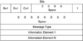
Multilink Frame Relay Link Integrity Protocol Control messages are transmitted in Multilink Frame Relay frames with the Control Bit set to 1. This serves to differentiate a Multilink Frame Relay data packet from a Multilink Frame Relay link control packet. The Begin (B) and End (E) bits in the headers indicate whether fragmentation has occurred. The control messages are sent without fragmentation (Bit B=1 and Bit E=1). The message consists of a Message Type element and multiple variable-length Information Element fields. The Multilink Frame Relay Link Integrity Protocol defines seven control messages for link management. The Message Type field in the Multilink Frame Relay Link Integrity Protocol message identifies the type of control message. The purposes of each Message Type value are described in Table 14-1.
Table 14-1. Values of Message Type Fields in Multilink Frame Relay Link Integrity Protocol Message
Message Type | Description |
|---|---|
ADD_LINK | Notifies the peer endpoint that the local endpoint supports frame processing and is ready to become operational |
ADD_LINK_ACK | Notifies the peer endpoint that the local endpoint has received a valid ADD_LINK message |
ADD_LINK_REJ | Notifies the peer endpoint that the local endpoint has received an invalid ADD_LINK message |
HELLO | Notifies the peer endpoint periodically that the local endpoint remains in the UP state |
HELLO_ACK | Notifies the peer endpoint that the local endpoint has received a valid HELLO message |
REMOVE_LINK | Notifies the peer endpoint that the local endpoint and layer management function is removing the bundle link from bundle operation |
REMOVE_LINK_ACK | Notifies the peer endpoint that the local endpoint has received a REMOVE_LINK message |
A Multilink Frame Relay Link Integrity Protocol message can consist of one or more Information Element fields, depending on the type of information it carries. Furthermore, Link Integrity Protocol Control messages are exchanged between peers independently on each link of a bundle.
Figure 14-3 shows the basic format of an Information Element field in the Multilink Frame Relay Link Integrity Protocol message. Table 14-2 explains the purpose of the various Information Element fields.
Table 14-2. Information Element Fields in Multilink Frame Relay Link Integrity Protocol

This section explains the basic operation involving bundle initialization and setup, management, and tearing down of the bundle link.
The ADD_LINK, ADD_LINK_ACK, and ADD_LINK_REJ messages in the Multilink Frame Relay Link Integrity Control Protocol are used to negotiate the setup of a bundle link between two associated peers or endpoints. When a physical interface is configured as a bundle link, the bundle link setup process is invoked, and an ADD_LINK message is sent out to the peer device on the new bundle link. At the same time, the N_MAX_RETRY counter is cleared and the T_ACK timer is started.
The bundle link establishment process is considered complete when an ADD_LINK_ACK message is received. When this happens, the T_ACK timer is reset and the T_HELLO timer is started. The T_HELLO timer is used to pace the exchange of periodic HELLO and HELLO_ACK messages between the peers for bundle management. However, if the T_ACK timer expires before the endpoint receives an ADD_LINK_ACK message, the bundle link endpoint retransmits the ADD_LINK message.
In the event of errors, the ADD_LINK_REJ message is used to indicate that an invalid ADD_LINK message has been received. For example, this can happen when the received bundle identification is not consistent with the bundle identification received from the other bundle link. The ADD_LINK_REJ message contains the cause for the rejection for diagnostic purposes.
Figure 14-4 shows the basic steps involved in establishing a bundle link between two endpoints.

When the bundle link is up, the peers exchange HELLO and HELLO_ACK messages in order to maintain the link. The periodic exchange of the HELLO and HELLO_ACK messages acts as a keepalive mechanism for the link. The HELLO message is used by a local endpoint to notify its peer that the bundle link is in the UP state. Both ends of a bundle link generate this message periodically based on the T_HELLO timer. The T_HELLO timer can be adjusted to control the rate at which HELLO messages are sent out. For example, reducing the value of the T_HELLO timer increases the frequency at which the Multilink peers poll each other. On Cisco routers, the default T_HELLO timer is set to 10 seconds, and the supported range is from 1 to 180 seconds.
On receiving a HELLO message, the remote peer responds with a HELLO_ACK message to indicate that it has received a valid HELLO message. If a peer does not receive a HELLO_ACK message from its peer after the T_HELLO timer expires, it retransmits the HELLO message, up to the maximum number of attempts specified by the N_MAX_RETRY counter. On Cisco routers, the N_MAX_RETRY counter is set to two tries, and the configurable range is from one to five tries.
The Multilink Frame Relay Link Integrity Protocol also specifies a set of rules for tearing down the bundle link. The REMOVE_LINK and REMOVE_LINK_ACK control messages are used to notify the remote peer that the local peer is removing the bundle link from bundle operation. A bundle link can be brought down by configurations. In this case, the bundle link sends a REMOVE_LINK message to its peer that it is releasing this bundle link member interface. On receiving the REMOVE_LINK message, the peer responds with the REMOVE_LINK_ACK message to indicate that it has received the REMOVE_LINK message request. At this time, the endpoint resets the N_MAX_RETRY counter, starts the T_ACK timer, and enters the idle state.
However, if the peer sending out the REMOVE_LINK message does not receive a REMOVE_LINK_ACK message from its peer before its T_ACK timer expires, it retransmits the REMOVE_LINK message up to the maximum number of attempts specified in the N_MAX_RETRY counter. If the local peer tearing down the bundle link does not receive the REMOVE_LINK_ACK message from its peer after the N_MAX_RETRY counter is exceeded, it continues to deactivate the bundle link at its local end.
The FRF.16 specification defines three system parameters for the basic Multilink Frame Relay operation. As mentioned, these parameters are the T_HELLO timer, the T_ACK timer, and the N_MAX_RETRY counter. The T_HELLO timer is used to control the rate at which HELLO messages are sent out for link management. The T_ACK timer indicates the period for which the peer should wait for ADD_LINK_ACK, HELLO_ACK, or REMOVE_LINK_ACK messages. Finally, the N_MAX_RETRY counter specifies the maximum number of retransmission attempts for HELLO or REMOVE_LINK messages after the T_ACK timer has expired.
Table 14-3 shows the default values of the Multilink Frame Relay system parameters. It is recommended to use the default values for the Multilink system parameters.
This section takes a closer look at Cisco's implementation of the Multilink Frame Relay feature in its Cisco IOS software.
Cisco's implementation of the Multilink Frame Relay feature is compliant with the Frame Relay Forum's FRF.16 standard specifications.
NOTE
The Multilink Frame Relay feature is released in Cisco IOS 12.2(8)T. It is supported on c2600, c3600, c3700, and c7200 series routers. The following Cisco Connection Online (CCO) site also lists the Cisco platforms supported by this feature: http://www.cisco.com/en/US/products/sw/iosswrel/ps1839/products_feature_guide09186a0080087cbf.html#1042570.
Note that Cisco's current phase of the Multilink Frame Relay feature implementation has the following restrictions:
ISDN interface and any other type of virtual interfaces cannot become part of the bundle link.
Frame Relay fragmentation (FRF.12) is not supported. Hence, the Multilink frames cannot be transmitted in fragments.
Multilink Frame Relay MIB (RFC 3020) is not supported.
FRF.9 hardware compression over Multilink Frame Relay is not supported.
The number of bundles that can be supported on a router is platform-dependent.
The FRF.16 specifications define four different classes of bandwidth (A, B, C, and D) to represent the trigger point of activating or deactivating the bundle. Class A is the default class of bandwidth. It brings up the bundle as long as one bundle link is active, and it brings down the bundle only when all bundle links are down. By contrast, Class B brings up the bundle only when all bundle links are up, and it brings down the bundle as long as one bundle link goes down. Class C is based on threshold, and Class D is implementation-specific. Cisco currently fully supports Class A, and it complies with the Class A bandwidth requirements in FRF.16. The remaining classes of bandwidth are not supported by Cisco in this phase of the Multilink Frame Relay implementation. For this reason, Classes B, C, and D are not addressed in this text.
The next section discusses the creation and use of the Multilink Frame Relay bundle interface involving its bundle links on Cisco routers.
A new virtual interface type was created in the Cisco IOS software in order to support the new Multilink Frame Relay feature. The Multilink Frame Relay interface is a multilink Frame Relay bundle interface, or logical interface. The Multilink Frame Relay interface is used to represent the bundle on which the Frame Relay data link protocols run and all Frame Relay VCs are built. In a nutshell, the Multilink Frame Relay interface emulates a physical interface for the transport of frames.
The bundle comprises two or more physical serial links, called bundle links. The bundle links are transparent to the Frame Relay data link layer, and thus, Frame Relay functionality cannot be enabled on them. On the other hand, Frame Relay functionality must be configured on the master bundle interface (Multilink Frame Relay interface). After the master bundle interface is created, the peer devices exchange Multilink Frame Relay Link Integrity Protocol Control messages to monitor the operation of the bundle links. Because more than one bundle interface can be created, the Multilink Frame Relay Link Integrity Protocol Control messages also serve to synchronize which bundle links should be associated with which bundles. The Multilink Frame Relay interface, or master bundle interface, is configured on a Cisco router with the following global configuration command:
Router(config)#interface mfr mfr-number
An Multilink Frame Relay interface supports Cisco or IETF Frame Relay encapsulations. The default Frame Relay encapsulation of the Multilink Frame Relay interface is Cisco. No other encapsulation types are allowed on the Multilink Frame Relay interface. To use Multilink Frame Relay between a Cisco device and a non-Cisco device, the IETF Frame Relay encapsulation type should be used. The regular Frame Relay supported functionalities can be configured directly on the Multilink Frame Relay interface or subinterface.
To associate a physical serial interface with the Multilink Frame Relay interface, the following interface level configuration command is used:
Router(config-if)#encapsulation frame-relay mfr mfr-number
This command configures the selected physical interface as an Multilink Frame Relay bundle link associated with the Multilink Frame Relay interface specified in the mfr-number parameter.
This section looks at the configuration tasks required to configure the Multilink Frame Relay feature on a Cisco router. In addition, all Multilink Frame Relay-related commands supported by the Cisco IOS are discussed.
The following procedures outline the steps required to create a bundle interface, configure the physical serial interfaces as bundle links, and associate the bundle links with the bundle interface. The optional configuration commands for tuning Multilink Frame Relay parameters on a Cisco router running Multilink Frame Relay are also explained.
Beginning in the global configuration mode, configure a Multilink Frame Relay bundle interface with the interface mfr number global configuration command. This creates a logical Multilink Frame Relay interface that represents the bundle.
Determine the physical Frame Relay serial interfaces to be configured as the bundle links and associated with the bundle interface. Select the physical interface and enter the interface configuration mode.
Configure the physical Frame Relay serial interface as a bundle link with the encapsulation frame-relay mfr number interface configuration command. The Multilink Frame Relay number parameter in the command is used to associate the bundle link with the bundle interface created. The number parameter must match the bundle interface number created.
(optional) The bundle interface can be assigned a Bundle Identification Name (BID) with the frame-relay multilink bid name bundle interface configuration command. This name is used to identify the bundle to the peer router so that the peer can synchronize itself with the local router. This command can only be configured at the Multilink Frame Relay interface. By default, the name of the Multilink Frame Relay interface is the “Multilink Frame Relay<number>” string.
(optional) The bundle link can be assigned a Link Identification Name (LID) with the frame-relay multilink lid name interface configuration command. The name is used to identify the bundle link to the peer router so that the peer can synchronize its physical link with the local router. The name can be up to 50 characters of alphanumeric and special characters. By default, the LID name is the physical interface name.
This section describes a few optional configuration commands for tuning Multilink Frame Relay behavior on a Cisco router.
The frame-relay multilink output-threshold bytes interface configuration command is an optional command. This command can be configured at the bundle interface or the bundle link level. When the command is enabled at the bundle interface level, all associated bundle links inherit the configured value. With this command, when a bundle link has transmitted at least the number of configured bytes, the next nonbusy bundle link in the bundle is used. The default value is 300 bytes.
The frame-relay multilink hello seconds interface configuration command is used to adjust the interval at which a bundle link sends out HELLO messages. The default value is 10 seconds (refer to Table 14-2).
The frame-relay multilink ack seconds interface configuration command is used to adjust the number of seconds a bundle link waits for a HELLO_ACK message before it retransmits the HELLO message. The default value is 4 seconds.
The frame-relay multilink retry number interface configuration command is used to configure the maximum number of retries for which the router resends a HELLO message while waiting for the HELLO_ACK. The default value is 2 tries.
As discussed earlier, the default value for the frame-relay multilink output-threshold command is 300 bytes. Note that the no form of the frame-relay multilink output-threshold command does not disable or turn off the command. The no form of the command merely resets the threshold to its default 300 bytes.
In situations where the true physical access speeds of the individual bundle links are identical or very close, load balancing can occur across the bundle links in the bundle without much user intervention. When a particular heavily loaded bundle link is busy transmitting a large packet, the load balancing mechanism rolls over to the next waiting bundle link. Without changing the default value of the frame-relay multilink output-threshold command, the number of bytes a bundle link transmits before rolling over to the next bundle link is 300 bytes.
On the contrary, in situations where the physical access speeds of individual bundle links vary greatly, the frame-relay multilink output-threshold command should be used to adjust the number of bytes each bundle link can transmit. To efficiently use the varied access speeds of the bundle links, the higher-speed bundle links should be configured with a proportionately larger transmit size. This should be taken into consideration to ensure load balancing works effectively across the bundle links.
The operation of the Multilink Frame Relay feature enabled on Cisco routers is covered with the help of some configuration examples. For the purpose of this discussion, the Frame Relay network illustrated in Figure 14-5 is used.

Figure 14-5 presents a simple scenario where Multilink Frame Relay can become very useful. In the network depicted in Figure 14-5, a typical customer connects its remote spoke office to its central hub office via a Frame Relay service provider. In this hub-and-spoke topology, the central hub site is connected to the provider's Frame Relay network via a high-speed T3 access link. Because of a surge in users' demand for more bandwidth, the customer has decided to purchase additional access links to cater to that need. However, in some situations, a T3 line might not be readily available in many regions. Likewise, the cost of a T3 line for a remote spoke office might prove to be too expensive. Under these circumstances, the customer can purchase an additional T1 line and make use of the Multilink Frame Relay feature to achieve the aggregate bandwidth required.
NOTE
The Cisco IOS Release used for these examples is 12.2(8)T. Note that different IOS releases might have slightly varying display output compared with what is observed in these examples.
Example 14-1 shows the running configurations of the routers illustrated in Figure 14-5.
Example 14-1. Running Configurations of R1 and R2 in Figure 14-5
! R1

<output omitted>

ip routing
!
interface MFR0
 no ip address
!
interface MFR0.1 point-to-point
 ip address 172.16.1.1 255.255.255.0
 frame-relay interface-dlci 103
!
interface Serial0
 no ip address
 encapsulation frame-relay MFR0
!
interface Serial3
 no ip address
 encapsulation frame-relay MFR0

! R2

<output omitted>

frame-relay switching
!
interface MFR0
 no ip address
 frame-relay intf-type dce
!
interface Serial3/0
 no ip address
 encapsulation frame-relay
 frame-relay intf-type dce
!
interface Serial3/3
 no ip address
 encapsulation frame-relay MFR0
!
interface Serial4/3
 no ip address
 encapsulation frame-relay MFR0
!
connect MFR MFR0 103 Serial3/0 301

! R3

<output omitted>

ip routing
!
interface Serial1/1
 no ip address
 encapsulation frame-relay
!
interface Serial1/1.1 point-to-point
 ip address 172.16.1.2 255.255.255.0
 frame-relay interface-dlci 301
As shown in Example 14-1, Multilink Frame Relay is configured between R1 and the service provider's Frame Relay switch R2 (a Cisco router configured with the Frame Relay switching feature). A bundle interface is created on each of the R1 and R2 routers. On R1, the bundle links that are configured as members of the bundle are serial0 and serial3. Similarly, serial3/3 and serial4/3 are the bundle links belonging to the bundle interface created on R2. After the bundle interface's status is in the UP state, only the master bundle interface is visible to the peers at the endpoints. The bundle links are transparent, and legacy Frame Relay functionalities are now configured on the bundle interface. The bundle interface acts like a normal Frame Relay serial interface, and logical subinterfaces can be created, as shown in the configuration example.
At R2, the Frame Relay switch provisions a Frame Relay connection between DLCI 103, on the Multilink Frame Relay interface, and DLCI 301, the T3 uplink connected to the router R3 at the central office.
An extended ping test is performed from router R1 to router R3 via the Multilink bundle. The extended ping, contents of the route table at R1, and the display of the show frame-relay map command are shown in Example 14-2.
Example 14-2. Connectivity Test Between R1 and R3 by Sending Packets Through the Bundle
R1#show ip route
Codes: C - connected, S - static, I - IGRP, R - RIP, M - mobile, B - BGP
       D - EIGRP, EX - EIGRP external, O - OSPF, IA - OSPF inter area
       N1 - OSPF NSSA external type 1, N2 - OSPF NSSA external type 2
       E1 - OSPF external type 1, E2 - OSPF external type 2, E - EGP
       i - IS-IS, L1 - IS-IS level-1, L2 - IS-IS level-2, ia - IS-IS inter area
       * - candidate default, U - per-user static route, o - ODR
       P - periodic downloaded static route

Gateway of last resort is not set

     172.16.0.0/24 is subnetted, 1 subnets
C       172.16.1.0 is directly connected, MFR0.1

R1#show frame-relay map
MFR0.1 (up): point-to-point dlci, dlci 103(0x67,0x1870), broadcast
status defined, active

R1#ping
Protocol [ip]:
Target IP address: 172.16.1.2
Repeat count [5]: 10
Datagram size [100]: 1500
Timeout in seconds [2]:
Extended commands [n]:
Sweep range of sizes [n]:
Type escape sequence to abort
Sending 10, 1500-byte ICMP Echos to 172.16.1.2, timeout is 2 seconds:
!!!!!!!!!!
Success rate is 100 percent (10/10), round-trip min/avg/max = 392/393/396 ms
Recall that earlier in this chapter, it was mentioned that Frame Relay is the only encapsulation allowed for the Multilink Frame Relay interface. Example 14-3 verifies this. Likewise, observe in the same example that Cisco Frame Relay encapsulation is the default, but IETF Frame Relay encapsulation is also supported.
Example 14-3. Encapsulation Type Allowed for Multilink Frame Relay Interface
R1#configure terminal
Enter configuration commands, one per line.  End with CNTL/Z
R1(config)#interface mfr0
R1(config-if)#encapsulation ?
  frame-relay  Frame Relay networks

R1(config-if)#encapsulation frame-relay ?
  ietf  Use RFC1490/RFC2427 encapsulation
  <cr>
The Frame Relay commands available to the Multilink Frame Relay interface are shown in Example 14-4. Compare this with the Frame Relay commands configurable under a regular Frame Relay serial interface in Example 14-5. From both examples, you should notice that both the regular serial interface setup with Frame Relay encapsulation and the virtual Multilink Frame Relay interface support the same set of Frame Relay commands.
Example 14-4. Frame Relay Commands Available to an Multilink Frame Relay Interface
R1(config)#interface mfr0
R1(config-if)#frame-relay ?
  address-reg            ELMI address registration
  broadcast-queue        Define a broadcast queue and transmit rate
  class                  Define a map class on the interface
  congestion-management  Enable Frame Relay congestion management
  de-group               Associate a DE group with a DLCI
  interface-dlci         Define a DLCI on an interface/subinterface
  interface-queue        configure PVC interface queueing
  intf-type              Configure a FR DTE/DCE/NNI interface
  inverse-arp            Enable/disable inverse ARP on a DLCI
  ip                     Frame Relay Internet Protocol config commands
  lapf                   set LAPF parameter
  lmi-n391dte            set full status polling counter
  lmi-n392dce            LMI error threshold
  lmi-n392dte            LMI error threshold
  lmi-n393dce            set LMI monitored event count
  lmi-n393dte            set LMI monitored event count
  lmi-t392dce            set DCE polling verification timer
  lmi-type               Use CISCO-ANSI-CCITT type LMI
  local-dlci             Set source DLCI when LMI is not supported
  map                    Map a protocol address to a DLCI address
  multicast-dlci         Set DLCI of a multicast group
  multilink              Set Multilink FR parameters
  payload-compression    Use payload compression
  policing               Enable Frame Relay policing
  priority-dlci-group    Define a priority group of DLCIs
  qos-autosense          enable QOS autosense
  route                  frame relay route for pvc switching
  svc                    Enable frame relay SVCs
  traffic-shaping        Enable Frame Relay Traffic Shaping
  traps-maximum          set max traps FR generates at link up or when getting
                         LMI Full Status message
Example 14-5. Frame Relay Commands Available to a Regular Frame Relay Serial Interface
R1(config)#interface serial2
R1(config-if)#frame-relay ?
  address-reg            ELMI address registration
  broadcast-queue        Define a broadcast queue and transmit rate
  class                  Define a map class on the interface
  congestion-management  Enable Frame Relay congestion management
  de-group               Associate a DE group with a DLCI
  interface-dlci         Define a DLCI on an interface/subinterface
  interface-queue        configure PVC interface queueing
  intf-type              Configure a FR DTE/DCE/NNI interface
  inverse-arp            Enable/disable inverse ARP on a DLCI
  ip                     Frame Relay Internet Protocol config commands
  lapf                   set LAPF parameter
  lmi-n391dte            set full status polling counter
  lmi-n392dce            LMI error threshold
  lmi-n392dte            LMI error threshold
  lmi-n393dce            set LMI monitored event count
  lmi-n393dte            set LMI monitored event count
  lmi-t392dce            set DCE polling verification timer
  lmi-type               Use CISCO-ANSI-CCITT type LMI
  local-dlci             Set source DLCI when LMI is not supported
  map                    Map a protocol address to a DLCI address
  multicast-dlci         Set DLCI of a multicast group
  payload-compression    Use payload compression
  policing               Enable Frame Relay policing
  priority-dlci-group    Define a priority group of DLCIs
  qos-autosense          enable QOS autosense
  route                  frame relay route for pvc switching
  svc                    Enable frame relay SVCs
  traffic-shaping        Enable Frame Relay Traffic Shaping
  traps-maximum          set max traps FR generates at link up or when getting
                         LMI Full Status message
This section discusses the various show commands for monitoring and maintaining Multilink Frame Relay on a Cisco router. The end of this section looks at the IOS debug commands available for troubleshooting Multilink Frame Relay. The network diagram portrayed in Figure 14-1 and the base configurations shown in Example 14-1 are used for this discussion.
Example 14-6 shows the output of the show interface mfr [mfr_number] command. This is executed on router R1 after the bundle interface has been created.
Example 14-6. Output of the show interface mfr Command at R1
R1#show interface mfr0
MFR0 is up, line protocol is up
  Hardware is Multilink Frame Relay bundle interface
  MTU 1500 bytes, BW 100000 Kbit, DLY 100000 usec,
     reliability 255/255, txload 1/255, rxload 1/255
  Encapsulation FRAME-RELAY, loopback not set
  Keepalive set (10 sec)
  DTR is pulsed for 2 seconds on reset
  LMI enq sent  781, LMI stat recvd 777, LMI upd recvd 0, DTE LMI up
  LMI enq recvd 10, LMI stat sent  0, LMI upd sent  0
  LMI DLCI 1023  LMI type is CISCO  frame relay DTE
  FR SVC disabled, LAPF state down
  Broadcast queue 0/64, broadcasts sent/dropped 96/0, interface broadcasts 0
  Last input 00:00:07, output never, output hang never
  Last clearing of "show interface" counters 02:11:37
  Input queue: 0/75/0/0 (size/max/drops/flushes); Total output drops: 0
  Queueing strategy: fifo
  Output queue :0/120 (size/max)
  5 minute input rate 0 bits/sec, 0 packets/sec
  5 minute output rate 0 bits/sec, 0 packets/sec
     902 packets input, 59517 bytes, 0 no buffer
     Received 0 broadcasts, 0 runts, 0 giants, 0 throttles
     0 input errors, 0 CRC, 0 frame, 0 overrun, 0 ignored, 0 abort
     898 packets output, 57829 bytes, 0 underruns
     0 output errors, 0 collisions, 0 interface resets
     0 output buffer failures, 0 output buffers swapped out
     0 carrier transitions
From the show output in Example 14-6, observe that the interface is a Multilink Frame Relay bundle interface, and LMI packets are being exchanged on the Multilink Frame Relay interface. Compare this with the show interface output of one of the bundle links (physical serial interface) in Example 14-7.
Example 14-7. show interface Output of a Bundle Link
R1#show interface serial0
Serial0 is up, line protocol is up
  Hardware is HD64570
  MTU 1500 bytes, BW 1544 Kbit, DLY 20000 usec,
     reliability 255/255, txload 1/255, rxload 1/255
  Encapsulation FRAME-RELAY, loopback not set
  Bundle Link of bundle MFR0
  Last input 00:00:05, output 00:00:05, output hang never
  Last clearing of "show interface" counters 02:40:36
  Input queue: 0/75/0/0 (size/max/drops/flushes); Total output drops: 0
  Queueing strategy: fifo
  Output queue :0/40 (size/max)
  5 minute input rate 0 bits/sec, 0 packets/sec
  5 minute output rate 0 bits/sec, 0 packets/sec
     2466 packets input, 55992 bytes, 0 no buffer
     Received 0 broadcasts, 0 runts, 0 giants, 0 throttles
     0 input errors, 0 CRC, 0 frame, 0 overrun, 0 ignored, 0 abort
     2467 packets output, 54252 bytes, 0 underruns
     0 output errors, 0 collisions, 2 interface resets
     0 output buffer failures, 0 output buffers swapped out
     5 carrier transitions
DCD=up  DSR=up  DTR=up  RTS=up  CTS=up
The output in Example 14-7 indicates that the bundle link (physical serial interface 0) is a member of the bundle MFR0.
The show frame-relay multilink command allows information of the Multilink Frame Relay interface and the associated bundle links to be displayed. The show frame-relay multilink command also offers other options. The detailed option provides the most information to the user, which includes the status of the bundle interface, the number of bundle links configured under the bundle, the name of the bundle identification and bundle link identifications, and detailed information of the Multilink Frame Relay Link Integrity Protocol Control messages exchanged. Example 14-8 shows the options available to the show frame-relay multilink command and a sample output of show frame-relay multilink detailed executed at R1.
Example 14-8. Output of show frame-relay multilink detailed Command at R1
R1#show frame-relay multilink ?
  Multilink Frame Relay       Multilink Frame Relay bundle interface
  Serial    Serial
  detailed  Detailed mfr interface info
  |         Output modifiers
  <cr>

R1#show frame-relay multilink detailed
Bundle: MFR0, State = up, class = A, fragmentation disabled
 BID = MFR0
 No. of bundle links = 2, Peer's bundle-id = MFR0
 Bundle links:

  Serial0, HW state = up, link state = Up, LID = Serial0
    Cause code = none, Ack timer = 4, Hello timer = 10,
    Max retry count = 2, Current count = 0,
    Peer LID = Serial4/3, RTT = 4 ms
    Statistics:
    Add_link sent = 2, Add_link rcv'd = 1,
    Add_link ack sent = 1, Add_link ack rcv'd = 2,
    Add_link rej sent = 0, Add_link rej rcv'd = 0,
    Remove_link sent = 0, Remove_link rcv'd = 0,
    Remove_link_ack sent = 0, Remove_link_ack rcv'd = 0,
    Hello sent = 1105, Hello rcv'd = 1106,
    Hello_ack sent = 1106, Hello_ack rcv'd = 1105,
    outgoing pak dropped = 0, incoming pak dropped = 0

  Serial3, HW state = up, link state = Up, LID = Serial3
    Cause code = none, Ack timer = 4, Hello timer = 10,
    Max retry count = 2, Current count = 0,
    Peer LID = Serial3/3, RTT = 4 ms
    Statistics:
    Add_link sent = 2, Add_link rcv'd = 1,
    Add_link ack sent = 1, Add_link ack rcv'd = 2,
    Add_link rej sent = 0, Add_link rej rcv'd = 0,
    Remove_link sent = 0, Remove_link rcv'd = 0,
    Remove_link_ack sent = 0, Remove_link_ack rcv'd = 0,
    Hello sent = 1106, Hello rcv'd = 1107,
    Hello_ack sent = 1107, Hello_ack rcv'd = 1106,
outgoing pak dropped = 0, incoming pak dropped = 0
Example 14-9 shows the corresponding output of the show frame-relay multilink detailed command executed at R2.
Example 14-9. Output of show frame-relay multilink detailed Command at R2
R2#show frame-relay multilink detailed
Bundle: MFR0, State = up, class = A, fragmentation disabled
 BID = MFR0
 No. of bundle links = 2, Peer's bundle-id = MFR0
 Bundle links:

  Serial4/3, HW state = up, link state = Up, LID = Serial4/3
    Cause code = none, Ack timer = 4, Hello timer = 10,
    Max retry count = 2, Current count = 0,
    Peer LID = Serial0, RTT = 4 ms
    Statistics:
    Add_link sent = 2, Add_link rcv'd = 2,
    Add_link ack sent = 2, Add_link ack rcv'd = 1,
    Add_link rej sent = 0, Add_link rej rcv'd = 0,
    Remove_link sent = 0, Remove_link rcv'd = 0,
    Remove_link_ack sent = 0, Remove_link_ack rcv'd = 0,
    Hello sent = 1135, Hello rcv'd = 1134,
    Hello_ack sent = 1134, Hello_ack rcv'd = 1135,
    outgoing pak dropped = 0, incoming pak dropped = 0

  Serial3/3, HW state = up, link state = Up, LID = Serial3/3
    Cause code = none, Ack timer = 4, Hello timer = 10,
    Max retry count = 2, Current count = 0,
    Peer LID = Serial3, RTT = 4 ms
    Statistics:
    Add_link sent = 2, Add_link rcv'd = 2,
    Add_link ack sent = 2, Add_link ack rcv'd = 1,
    Add_link rej sent = 0, Add_link rej rcv'd = 0,
    Remove_link sent = 0, Remove_link rcv'd = 0,
    Remove_link_ack sent = 0, Remove_link_ack rcv'd = 0,
    Hello sent = 1136, Hello rcv'd = 1135,
    Hello_ack sent = 1135, Hello_ack rcv'd = 1136,
    outgoing pak dropped = 0, incoming pak dropped = 0
In the next example, the bundle identification and bundle link identification are assigned to the bundle interface and bundle links, respectively. This is achieved with the frame-relay multilink bid name and frame-relay multilink lid name configuration commands. Note that as shown in Example 14-8 and Example 14-9, the default bundle identification is the name of the Multilink Frame Relay interface created and the default bundle link identification is the name of the member physical serial interface.
The bid and lid are changed by adding the frame-relay multilink bid and frame-relay multilink lid commands to the base configurations in Example 14-1. The resultant configurations of the new commands are shown in Example 14-10.
Example 14-10. Assigning bid and lid to the Bundle Interface and Bundle Links at R1
R1#configure terminal
Enter configuration commands, one per line.  End with CNTL/Z
R1(config)#interface mfr0
R1(config-if)#frame-relay multilink bid Multilink Frame Relay_BUNDLE
R1(config-if)#exit
R1(config)#interface Serial0
R1(config-if)#frame-relay multilink lid REMOTE_LINK_1
R1(config-if)#interface Serial3
R1(config-if)#frame-relay multilink lid REMOTE_LINK_2
R1(config-if)#end
R1#

R1#show running-config

<output omitted>
!
interface MFR0
 no ip address
 frame-relay multilink bid Multilink Frame Relay_BUNDLE
!
interface MFR0.1 point-to-point
 ip address 172.16.1.1 255.255.255.0
 frame-relay interface-dlci 103
!
interface Serial0
 no ip address
 encapsulation frame-relay MFR0
 frame-relay multilink lid REMOTE_LINK_1
!
interface Serial3
 no ip address
 encapsulation frame-relay MFR0
 frame-relay multilink lid REMOTE_LINK_2
Example 14-11 shows the output of the show frame-relay multilink detailed command at R2 after the bid and lid are changed at R1. Note that R2 still shows the same output as in Example 14-9. In order for the changes to go into effect, reset the Multilink Frame Relay interface by performing a shut, followed by a no shut.
Example 14-11. Output of show frame-relay multilink detailed at R2 After Changing bid and lid at R1
R2#show frame-relay multilink detailed
Bundle: MFR0, State = up, class = A, fragmentation disabled
 BID = MFR0
 No. of bundle links = 2, Peer's bundle-id = MFR0
 Bundle links:

  Serial4/3, HW state = up, link state = Up, LID = Serial4/3
    Cause code = none, Ack timer = 4, Hello timer = 10,
    Max retry count = 2, Current count = 0,
    Peer LID = Serial0, RTT = 4 ms
    Statistics:
    Add_link sent = 2, Add_link rcv'd = 2,
    Add_link ack sent = 2, Add_link ack rcv'd = 1,
    Add_link rej sent = 0, Add_link rej rcv'd = 0,
    Remove_link sent = 0, Remove_link rcv'd = 0,
    Remove_link_ack sent = 0, Remove_link_ack rcv'd = 0,
    Hello sent = 1220, Hello rcv'd = 1219,
    Hello_ack sent = 1219, Hello_ack rcv'd = 1220,
    outgoing pak dropped = 0, incoming pak dropped = 0

  Serial3/3, HW state = up, link state = Up, LID = Serial3/3
    Cause code = none, Ack timer = 4, Hello timer = 10,
    Max retry count = 2, Current count = 0,
    Peer LID = Serial3, RTT = 4 ms
    Statistics:
    Add_link sent = 2, Add_link rcv'd = 2,
    Add_link ack sent = 2, Add_link ack rcv'd = 1,
    Add_link rej sent = 0, Add_link rej rcv'd = 0,
    Remove_link sent = 0, Remove_link rcv'd = 0,
    Remove_link_ack sent = 0, Remove_link_ack rcv'd = 0,
    Hello sent = 1221, Hello rcv'd = 1220,
    Hello_ack sent = 1220, Hello_ack rcv'd = 1221,
outgoing pak dropped = 0, incoming pak dropped = 0
The show frame-relay multilink detailed command is executed again at R2 after performing a shut/no shut at R1. The whole process is illustrated in Example 14-12.
Example 14-12. Resetting the Multilink Frame Relay Interface at R1 in Order for Changes to bid and lid to Kick In
R1#configure terminal
Enter configuration commands, one per line.  End with CNTL/Z
R1(config)#interface mfr0
R1(config-if)#shutdown
R1(config-if)#no shutdown
R1(config-if)#end

R2#show frame-relay multilink detailed
Bundle: MFR0, State = up, class = A, fragmentation disabled
 BID = MFR0
 No. of bundle links = 2, Peer's bundle-id = Multilink Frame Relay_BUNDLE
 Bundle links:

  Serial4/3, HW state = up, link state = Up, LID = Serial4/3
    Cause code = none, Ack timer = 4, Hello timer = 10,
    Max retry count = 2, Current count = 0,
    Peer LID = REMOTE_LINK_1, RTT = 12 ms
    Statistics:
    Add_link sent = 3, Add_link rcv'd = 3,
    Add_link ack sent = 3, Add_link ack rcv'd = 2,
    Add_link rej sent = 0, Add_link rej rcv'd = 0,
    Remove_link sent = 0, Remove_link rcv'd = 1,
    Remove_link_ack sent = 1, Remove_link_ack rcv'd = 0,
    Hello sent = 1233, Hello rcv'd = 1231,
    Hello_ack sent = 1231, Hello_ack rcv'd = 1233,
    outgoing pak dropped = 0, incoming pak dropped = 0

  Serial3/3, HW state = up, link state = Up, LID = Serial3/3
    Cause code = none, Ack timer = 4, Hello timer = 10,
    Max retry count = 2, Current count = 0,
    Peer LID = REMOTE_LINK_2, RTT = 12 ms
    Statistics:
    Add_link sent = 3, Add_link rcv'd = 3,
    Add_link ack sent = 3, Add_link ack rcv'd = 2,
    Add_link rej sent = 0, Add_link rej rcv'd = 0,
    Remove_link sent = 0, Remove_link rcv'd = 1,
    Remove_link_ack sent = 1, Remove_link_ack rcv'd = 0,
    Hello sent = 1234, Hello rcv'd = 1232,
    Hello_ack sent = 1232, Hello_ack rcv'd = 1234,
outgoing pak dropped = 0, incoming pak dropped = 0
The next example looks at the configuration commands for tuning the Multilink Frame Relay system parameters. These are the frame-relay multilink hello seconds, frame-relay multilink ack seconds, and frame-relay multilink retry number interface configuration commands. Observe in the show frame-relay multilink detailed command output in Example 14-12 that the default values are 10 seconds, 4 seconds, and 2 tries, respectively.
Example 14-13 shows the configuration command executed at R2 for adjusting the default system parameters.
Example 14-13. Adjusting the Default System Parameters
R2#configure terminal
Enter configuration commands, one per line.  End with CNTL/Z
R2(config)#interface s3/3
R2(config-if)#frame-relay multilink hello 30
R2(config-if)#frame-relay multilink retry 1
R2(config-if)#frame-relay multilink ack 2
R2(config-if)#end
R2#

R2#show frame-relay multilink detailed
Bundle: MFR0, State = up, class = A, fragmentation disabled
 BID = MFR0
 No. of bundle links = 2, Peer's bundle-id = Multilink Frame Relay_BUNDLE
 Bundle links:

  Serial4/3, HW state = up, link state = Up, LID = Serial4/3
    Cause code = none, Ack timer = 4, Hello timer = 10,
    Max retry count = 2, Current count = 0,
    Peer LID = REMOTE_LINK_1, RTT = 4 ms
    Statistics:
    Add_link sent = 4, Add_link rcv'd = 5,
    Add_link ack sent = 4, Add_link ack rcv'd = 3,
    Add_link rej sent = 0, Add_link rej rcv'd = 0,
    Remove_link sent = 0, Remove_link rcv'd = 1,
    Remove_link_ack sent = 1, Remove_link_ack rcv'd = 0,
    Hello sent = 1318, Hello rcv'd = 1315,
    Hello_ack sent = 1315, Hello_ack rcv'd = 1315,
    outgoing pak dropped = 0, incoming pak dropped = 0

  Serial3/3, HW state = up, link state = Up, LID = Serial3/3
    Cause code = none, Ack timer = 2, Hello timer = 30,
    Max retry count = 1, Current count = 0,
    Peer LID = REMOTE_LINK_2, RTT = 4 ms
    Statistics:
    Add_link sent = 3, Add_link rcv'd = 3,
    Add_link ack sent = 3, Add_link ack rcv'd = 2,
    Add_link rej sent = 0, Add_link rej rcv'd = 0,
    Remove_link sent = 0, Remove_link rcv'd = 1,
    Remove_link_ack sent = 1, Remove_link_ack rcv'd = 0,
    Hello sent = 1313, Hello rcv'd = 1317,
    Hello_ack sent = 1317, Hello_ack rcv'd = 1313,
outgoing pak dropped = 0, incoming pak dropped = 0
The output of the show frame-relay multilink detailed command reflects the new system parameters (ACK = 2, Hello = 30, and retry = 1) after the commands are configured on the second bundle link at R2. The configuration commands undertaken in Example 14-13 at R2 only affect the individual bundle link where they are configured. They do not affect the other bundle links in the bundle.
NOTE
It is recommended to keep the system parameter values at their default unless it becomes absolutely necessary to change them.
One of the main functionalities of the Multilink Frame Relay feature is the ability to failover to an alternate bundle link in the bundle should a bundle link go down. Referring again to the diagram in Figure 14-5, you can verify resiliency by shutting down one of the bundle links between R1 and R2 while traffic is being carried across the bundle from R1 to R3. To carry out this experiment, an extended ping to R3 with a large number of packets is performed at R1. While active packets are traversing over the bundle, you can shut down one of the bundle links between routers R1 and R2. In this case, the traffic should not be disrupted as long as there is at least one active bundle link in the bundle.
Example 14-14 shows what happens when a bundle link is shut down at the same time that an extended ping with a count of 1000 packets is performed across the Multilink bundle. The purpose of this example is to simulate a bundle link failure and to verify that there is no disruption to normal traffic flow as long as there are other active bundle links in the bundle.
Example 14-14. Verifying Bundle Resiliency by Shutting Down a Bundle Link While Traffic Is Transmitting
R1#ping
Protocol [ip]:
Target IP address: 172.16.1.2
Repeat count [5]: 1000
Datagram size [100]:
Timeout in seconds [2]:
Extended commands [n]:
Sweep range of sizes [n]:
Type escape sequence to abort
Sending 1000, 100-byte ICMP Echos to 172.16.1.2, timeout is 2 seconds:
!!!!!!!!!!!!!!!!!!!!!!!!!!!!!!!!!!!!!!!!!!!!!!!!!!!!!!!!!!!!!!!!!!!!!!
!!!!!!!!!!!!!!!!!!!!!!!!!!!!!!!!!!!!!!!!!!!!!!!!!!!!!!!!!!!!!!!!!!!!!!
!!!!!!!!!!!!!!!!!!!!!!!!!!!!!!!!!!!!!!!!!!!!!!!!!!!!!!!!!!!!!!!!!!!!!!
!!!!!!!!!!!!!!!!!!!!!!!!!!!!!!!!!!!!!!!!!!!!!!!!!!!!!!!!!!!!!!!!!!!!!!

Note: Ping is continuing at this point

R2#configure terminal
Enter configuration commands, one per line.  End with CNTL/Z
R2(config)#interface s3/3
R2(config-if)#shutdown
R2(config-if)#end
R2#

R2#show frame-relay multilink detailed
Bundle: MFR0, State = up, class = A, fragmentation disabled
 BID = MFR0
 No. of bundle links = 2, Peer's bundle-id = Multilink Frame Relay_BUNDLE
 Bundle links:

  Serial4/3, HW state = up, link state = Up, LID = Serial4/3
    Cause code = none, Ack timer = 4, Hello timer = 10,
    Max retry count = 2, Current count = 0,
    Peer LID = REMOTE_LINK_1, RTT = 4 ms
    Statistics:
    Add_link sent = 5, Add_link rcv'd = 6,
    Add_link ack sent = 5, Add_link ack rcv'd = 4,
    Add_link rej sent = 0, Add_link rej rcv'd = 0,
    Remove_link sent = 1, Remove_link rcv'd = 1,
    Remove_link_ack sent = 1, Remove_link_ack rcv'd = 0,
    Hello sent = 1440, Hello rcv'd = 1438,
    Hello_ack sent = 1438, Hello_ack rcv'd = 1437,
    outgoing pak dropped = 0, incoming pak dropped = 0

  Serial3/3, HW state = Administratively down, link state = Down_idle, LID = Serial3/3
    Cause code = bundle link idle, Ack timer = 4, Hello timer = 10,
    Max retry count = 2, Current count = 0,
    Peer LID = , RTT = 4 ms
    Statistics:
    Add_link sent = 5, Add_link rcv'd = 5,
    Add_link ack sent = 5, Add_link ack rcv'd = 4,
    Add_link rej sent = 0, Add_link rej rcv'd = 0,
    Remove_link sent = 3, Remove_link rcv'd = 1,
    Remove_link_ack sent = 1, Remove_link_ack rcv'd = 0,
    Hello sent = 1374, Hello rcv'd = 1439,
    Hello_ack sent = 1439, Hello_ack rcv'd = 1374,
outgoing pak dropped = 0, incoming pak dropped = 0

R1#ping
Protocol [ip]:
Target IP address: 172.16.1.2
Repeat count [5]: 1000
Datagram size [100]:
Timeout in seconds [2]:
Extended commands [n]:
Sweep range of sizes [n]:
Type escape sequence to abort.
Sending 1000, 100-byte ICMP Echos to 172.16.1.2, timeout is 2 seconds:
!!!!!!!!!!!!!!!!!!!!!!!!!!!!!!!!!!!!!!!!!!!!!!!!!!!!!!!!!!!!!!!!!!!!!!
!!!!!!!!!!!!!!!!!!!!!!!!!!!!!!!!!!!!!!!!!!!!!!!!!!!!!!!!!!!!!!!!!!!!!!
!!!!!!!!!!!!!!!!!!!!!!!!!!!!!!!!!!!!!!!!!!!!!!!!!!!!!!!!!!!!!!!!!!!!!!
!!!!!!!!!!!!!!!!!!!!!!!!!!!!!!!!!!!!!!!!!!!!!!!!!!!!!!!!!!!!!!!!!!!!!!
!!!!!!!!!!!!!!!!!!!!!!!!!!!!!!!!!!!!!!!!!!!!!!!!!!!!!!!!!!!!!!!!!!!!!!
!!!!!!!!!!!!!!!!!!!!!!!!!!!!!!!!!!!!!!!!!!!!!!!!!!!!!!!!!!!!!!!!!!!!!!
!!!!!!!!!!!!!!!!!!!!!!!!!!!!!!!!!!!!!!!!!!!!!!!!!!!!!!!!!!!!!!!!!!!!!!
!!!!!!!!!!!!!!!!!!!!!!!!!!!!!!!!!!!!!!!!!!!!!!!!!!!!!!!!!!!!!!!!!!!!!!
!!!!!!!!!!!!!!!!!!!!!!!!!!!!!!!!!!!!!!!!!!!!!!!!!!!!!!!!!!!!!!!!!!!!!!
!!!!!!!!!!!!!!!!!!!!!!!!!!!!!!!!!!!!!!!!!!!!!!!!!!!!!!!!!!!!!!!!!!!!!!
!!!!!!!!!!!!!!!!!!!!!!!!!!!!!!!!!!!!!!!!!!!!!!!!!!!!!!!!!!!!!!!!!!!!!!
!!!!!!!!!!!!!!!!!!!!!!!!!!!!!!!!!!!!!!!!!!!!!!!!!!!!!!!!!!!!!!!!!!!!!!
!!!!!!!!!!!!!!!!!!!!!!!!!!!!!!!!!!!!!!!!!!!!!!!!!!!!!!!!!!!!!!!!!!!!!!
!!!!!!!!!!!!!!!!!!!!!!!!!!!!!!!!!!!!!!!!!!!!!!!!!!!!!!!!!!!!!!!!!!!!!!
!!!!!!!!!!!!!!!!!!!!
Success rate is 100 percent (1000/1000), round-trip min/avg/max = 28/30/56 ms
The last configuration command discussed here is the frame-relay multilink output-threshold bytes interface configuration command. This command is always active and cannot be turned off when Multilink Frame Relay is configured. The default value is 300 bytes. The default value should be used when all bundle links in the bundle are of the same type and speed. However, if the bundle links are of varying speeds, the frame-relay multilink output-threshold command can be used to assign a higher byte size to the higher-speed bundle link, with the configured byte size on the higher-speed bundle link proportionally larger than the lower-speed bundle link. This helps to ensure that the traffic load is evenly distributed between the highest and lowest speed bundle links.
This section looks at the debug commands available for troubleshooting Multilink Frame Relay-specific issues on a Cisco router. The debug frame-relay multilink command can be used to display all debug messages related to Multilink Frame Relay bundles and bundle links. All Multilink Frame Relay data and control packets are captured, which might negatively impact the performance of the router. In its place, the more specific debug frame-relay multilink control command can be used to capture only Multilink Frame Relay control packets. The more specific debug frame-relay multilink control command should be used instead of the generic debug frame-relay multilink command when troubleshooting standard Multilink Frame Relay link negotiation issues.
Example 14-15 shows a sample output of the debug frame-relay multilink control command turned on at R1.
Example 14-15. Turning on debug frame-relay multilink control Command and Observing the debug Output at R1
R1#debug frame-relay multilink control Displaying Multilink FR control packets 04:23:35: Serial0(i) : msg = Add_link, Link = Serial0, Bundle = MFR0, Link id =REMOTE_LINK_1, BL state = Ack_rx E1 00 01 01 07 4D 46 52 30 00 04:23:35: Serial0(o) : msg = Add_link_ack, Link = Serial0, Bundle = MFR0, Link id =
The debug output in Example 14-15 shows the exchange of Multilink Frame Relay Link Integrity Protocol Control messages between R1 and R2 after the Multilink Frame Relay interface is administratively enabled with no shut.
This chapter covered Cisco's implementation of the Multilink Frame Relay feature, which is based on the Frame Relay Forum Implementation Agreement Document Number FRF.16. This chapter looked at the advantages provided by the Multilink Frame Relay feature and the benefits of bandwidth aggregation that it brings to certain Frame Relay users. Then this chapter explained the mechanisms and basic operation of Multilink Frame Relay, including the Link Integrity Control Protocol, which is used to set up Multilink Frame Relay bundles. This chapter also presented a simple scenario involving the Multilink Frame Relay feature. The scenario described how the Multilink Frame Relay feature is typically used through the use of practical configuration examples. The chapter discussed the necessary Cisco IOS configuration tasks and configuration commands for configuring the Multilink Frame Relay feature. The closing sections of this chapter covered the Cisco IOS show and debug commands for monitoring and maintaining Multilink Frame Relay on a Cisco router.
The next chapter discusses Frame Relay compression. Both software- and hardware-based compression are covered.
Frame Relay Forum Implementation Agreement FRF.16.1: Multilink Frame Relay UNI/NNI Implementation Agreement, May 2002: http://www.mplsforum.org/frame/Approved/FRF.16/frf16.1.pdf
Cisco IOS Release 12.2(8)T New Features configuration guide: http://www.cisco.com/univercd/cc/td/doc/product/software/ios122/122newft/122t/122t8/ft_mfr.htm