The previous chapters described the quality of service (QoS) features related to queuing for Frame Relay services. This chapter describes in detail the Frame Relay Queuing and Fragmentation at the Interface feature. This new feature allows Low Latency Queuing (LLQ) for Frame Relay (see Chapter 18, “Frame Relay Class-Based Weighted Fair Queuing (CBWFQ) and Low Latency Queuing (LLQ)”) and Frame Relay FRF.12 End-to-End Fragmentation (see Chapter 16, “Frame Relay Fragmentation”) to be supported at the Frame Relay main interface level.
This chapter begins with an overview of the components supported by the Frame Relay Queuing and Fragmentation at the Interface feature. It then discusses the benefits the Frame Relay Queuing and Fragmentation at the Interface feature provides over LLQ for Frame Relay and Frame Relay FRF.12 End-to-End Fragmentation. These are QoS features for Frame Relay supported only at the PVC level. This chapter then provides configuration examples using practical scenarios to illustrate how to deploy Frame Relay Queuing and Fragmentation at the Interface and to demonstrate the configuration tasks involved in configuring the feature on a Cisco router. Finally, this chapter explains the relevant Cisco IOS show and debug commands for monitoring and maintaining Frame Relay Queuing and Fragmentation at the Interface configurations on Cisco routers.
The topics and questions that this chapter addresses include the following:
Overview of Frame Relay Queuing and Fragmentation at the Interface feature
Differences between Frame Relay Queuing and Fragmentation at the Interface and LLQ for Frame Relay and Frame Relay FRF.12 End-to-End Fragmentation at the PVC level
Configuring the Frame Relay Queuing and Fragmentation at the Interface feature on a Cisco router
Applying the Frame Relay Queuing and Fragmentation at the Interface feature in a scenario example
Monitoring and maintaining Frame Relay Queuing and Fragmentation at the Interface configurations with Cisco IOS show and debug commands on Cisco routers
After completing this chapter, readers will recognize the benefits of the Frame Relay Queuing and Fragmentation at the Interface feature. The main benefit of the feature is providing customers and users with a simplified configuration to deploy LLQ and Frame Relay FRF.12 to a group of Frame Relay PVCs created on the main interface and subinterfaces. Readers will also become familiar with the configuration tasks and commands involved in setting up the Frame Relay Queuing and Fragmentation at the Interface feature on the main interface. Readers will become familiar with the relevant Cisco IOS show and debug commands for monitoring and maintaining the Frame Relay Queuing and Fragmentation at the Interface feature on Cisco routers.
This section discusses the benefits of the Frame Relay Queuing and Fragmentation at the Interface feature. The Frame Relay Queuing and Fragmentation at the Interface feature provides customers and users with a simplified configuration for supporting LLQ, Frame Relay FRF.12 End-to-End Fragmentation, and subrate shaping on a group of Frame Relay PVCs created on the main interface or logical subinterfaces. In addition, the Frame Relay Queuing and Fragmentation at the Interface feature offers flexible bandwidth allocation to the traffic. It provides a subrate shaping function to shape user traffic up to the configured interface shaping rate.
Before the release of the Frame Relay Queuing and Fragmentation at the Interface feature, every Frame Relay PVC that required LLQ or FRF.12 Fragmentation had to have an LLQ service policy or FRF.12 configurations configured in a Frame Relay map class and applied to each individual Frame Relay PVC. The new feature presents a simplified way of supporting queuing and fragmentation. It allows a single queuing and fragmentation policy configured on the Frame Relay main interface to be applied to all Frame Relay PVCs created on that main interface and its subinterfaces.
As a result, the new Frame Relay Queuing and Fragmentation at the Interface feature allows LLQ and FRF.12 to be collectively configured at the Frame Relay interface level. This eliminates the requirement to configure a low-latency service policy on each Frame Relay PVC individually. Effectively, the Frame Relay Queuing and Fragmentation at the Interface feature enhances the scalability of the LLQ and FRF.12 features by significantly reducing the configuration complexities involved, especially when either LLQ or FRF.12 needs to be provisioned on a large number of Frame Relay DLCIs created under the main interface. In addition to supporting LLQ and FRF.12 on the main Frame Relay interface, a subrate shaper is used to manage output traffic rate on the main interface.
When an LLQ policy map is applied to the interface, traffic through the interface is identified via class maps and is directed to either the priority queue or the class-default queue. Delay-sensitive traffic, such as voice, should be classified as high priority by the class maps and queued on the priority queue. The remaining traffic that does not meet the classifications of the high-priority queue is queued on the class-default queue. Together, the frames from both high-priority and class-default queues are subjected to fragmentation and interleaving at the interface. Frames that exceed the configured fragment size for FRF.12 End-to-End fragmentation at the interface are fragmented.
As part of this new feature, FRF.12 End-to-End Fragmentation can now be configured at the Frame Relay main interface level. When FRF.12 End-to-End Fragmentation is enabled on an interface with a user-defined fragment size, all PVCs on the main interface and its subinterfaces have FRF.12 End-to-End Fragmentation enabled with the same configured fragment size. To maintain low latency and low jitters for high-priority traffic, you are recommended to configure the fragment size to be greater than the largest high-priority frame that is expected. In this way, the high-priority frames are not fragmented. They are interleaved with the fragmented frames from the class-default queue to achieve the highest level of QoS transmission for high-priority traffic.
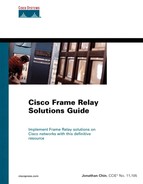
The Frame Relay Queuing and Fragmentation at the Interface feature enables nonfragmented high-priority frames to be interleaved together with fragmented low-priority frames for transmission. For interleaving of frames to work properly, some conditions have to be met. First of all, both interface level LLQ policy and FRF.12 Fragmentation must be configured. Next, the subrate shaping at the interface level must be turned off. Finally, for interleaving to work efficiently, the chosen fragment size should be greater than the largest high-priority frame. This is to ensure that the high-priority frames are not fragmented and delayed behind the fragmented data frames. Figure 19-1 illustrates the Frame Relay Queuing and Fragmentation at the Interface and interleaving process.
The Frame Relay Queuing and Fragmentation at the Interface feature supports a subrate shaper to limit the burst of traffic up to the physical interface line rate or the aggregate throughput governed by the interface shaping rate. If shaping is not configured, each Frame Relay PVC can send bursts up to the physical interface line rate. In addition, notice in Example 19-1 and Example 19-2 that Frame Relay fragmentation at the interface level cannot be supported together with the legacy Frame Relay Traffic Shaping feature.
Example 19-1. Interface-Level Fragmentation Cannot Be Enabled if FRTS Has Been Configured on the Interface
Router#configure terminal
Enter configuration commands, one per line.  End with CNTL/Z.
Router(config)#interface serial2/1
Router(config-if)#encapsulation frame-relay
Router(config-if)#frame-relay traffic-shaping
Router(config-if)#frame-relay fragment 100 end-to-end
Interface fragmentation can not be enabled while FRTS is configured.
Example 19-2. FRTS Cannot Be Enabled if Interface-Level Fragmentation Has Been Configured on the Interface
Router(config)#interface serial2/1
Router(config-if)#encapsulation frame-relay
Router(config-if)#frame-relay fragment 100 end-to-end
Router(config-if)#frame-relay traffic-shaping
Disable interface level end-to-end fragmentation first.
To support the new feature, a subrate shaper is used at the interface. When shaping is configured at the interface and the traffic rate exceeds the configured shaping rate, the traffic is queued at the shaping layer using fair queuing. At the interface level, the frames are queued using the configured queuing strategy or the default queuing method for the interface.
When subrate shaping is configured, interleaving of high-priority frames does not work. To use interleaving, subrate shaping must be disabled. When subrate shaping is not used, each Frame Relay PVC under the main interface or its subinterfaces is permitted to burst up to the physical line rate of the interface.
In all, the Frame Relay Queuing and Fragmentation at the Interface feature provides queuing, fragmentation, and shaping functionalities at the Frame Relay interface. This provides the benefit of a simple configuration for LLQ and fragmentation by applying a joint QoS policy to all Frame Relay PVCs under the main interface and its subinterfaces. With Frame Relay Queuing and Fragmentation at the Interface, users no longer need to configure QoS on each Frame Relay PVC individually. What is more, the Frame Relay Queuing and Fragmentation at the Interface feature avoids bandwidth partitioning between Frame Relay PVCs while preserving the logical separation of traffic classes on the Frame Relay PVCs.
The Frame Relay Queuing and Fragmentation at the Interface feature supports the following features:
Frame Relay fragmentation with hardware compression
Frame Relay payload compression
IP header compression
Voice over Frame Relay (VoFR)
Weighted Random Early Detection (WRED)
In general, the Frame Relay compression features greatly reduce network overhead and help customers to maximize their network throughputs and efficiency over low-bandwidth links. Frame Relay Queuing and Fragmentation at the Interface level supports hardware-assisted compression. Hardware-based compression offloads computationally intensive compression calculations from the routers' CPUs. This helps to free up critical resources on the router to allow it to support other features and functionalities. Frame Relay compression is covered in Chapter 15, “Compression over Frame Relay.”
VoFR allows a router to carry voice traffic, such as telephone calls and faxes, over a Frame Relay network. VoFR is covered extensively in Cisco Press's book Cisco Voice over Frame Relay, ATM, and IP by Stephen McQuerry, Kelly McGrew, and Stephen Foy (2001, ISBN: 1578702275). WRED provides a congestion avoidance mechanism for TCP by randomly dropping packets before periods of high congestion. WRED is covered in Chapter 21, “Weighted Random Early Detection (WRED) for Frame Relay.”
The following are not supported by the Frame Relay Queuing and Fragmentation at the Interface feature:
Frame Relay Traffic Shaping with interface fragmentation
Frame Relay class-based fragmentation with interface fragmentation
Frame Relay switched virtual circuits (SVCs)
Hierarchical shaping and multiple shapers
This section describes the tasks required to configure the Frame Relay Queuing and Fragmentation at the Interface feature on a Cisco router.
NOTE
The Frame Relay Queuing and Fragmentation at the Interface feature was released in Cisco IOS Release 12.2(13)T.
]To configure the Frame Relay Queuing and Fragmentation at the Interface feature on a Cisco router, perform the following configuration steps:
Define traffic classifications by creating a class-map with the class-map class-name global configuration command. The class-map is needed to classify traffic to their respective queues. The characteristics of the class are determined by the match criteria configured in the class-map. Refer to the Modular Quality of Service Command Line Interface (MQC) configurations in Chapter 18 on how to set up a class-map for traffic classifications.
Set up a policy map with the policy-map policy-map global configuration command. In the policy-map created, specify the name of class to be associated with the strict priority queue and the amount of bandwidth, in kbps, to be assigned to the class. This is configured with the priority bandwidth-kbps policy-map-class configuration command.
(optional) In the policy-map created, specify the name of the class to be associated with the bandwidth queues and specify the amount of bandwidth, in kbps, to be assigned to the class. This is configured with the bandwidth bandwidth-kps policy-map-class configuration command. Take note that by default, the sum of all bandwidth allocation on an interface cannot exceed 75 percent of the total available interface bandwidth. However, this can be overridden by the max-reserved-bandwidth command.
(optional) To configure shaping in addition to queuing on the Frame Relay interface, use the predefined class-default class to configure the shaping policy. The shaping policy configured in the class-default class acts as the parent policy, and all traffic for the entire interface is shaped. The shape [average | peak] mean-rate [[burst-size] [excess-burst-size]] policy-map-class configuration command is used to define the shaping policy.
After the overall LLQ service policy is defined in the earlier steps, enter the interface configuration mode of the Frame Relay interface and configure Frame Relay encapsulation with the encapsulation frame-relay interface configuration command. Next, apply the LLQ service-policy to the interface with service-policy output policy-map-name interface configuration command. Finally, enable FRF.12 End-to-End Fragmentation on the interface with the frame-relay fragment fragment-size end-to-end interface configuration command.
NOTE
The class-default class is meant for classifying traffic that does not fall into one of the user-defined classes. Although the class-default class is predefined when the policy map is created, it should be configured. Otherwise, traffic that does not match any of the user-defined classes is only given best-effort treatment. As mentioned, when configuring the shaping policy for the LLQ service-policy, use the class-default class.
This section uses the Frame Relay network exemplified in Figure 19-2 to explain Frame Relay Queuing and Fragmentation at the Interface and to describe the feature in action with configuration examples.

The Open Shortest Path First (OSPF) dynamic routing protocol is chosen to disseminate network layer routing information between the sites on the Frame Relay network, as shown in the next figure. Figure 19-3 shows the OSPF information of the network.
The configuration examples of the routers in Figure 19-2 (and Figure 19-3) are shown in Example 19-3.
Example 19-3. Configuration Examples of Routers R1, R2, and R3 in Figure 19-2
! Router R1:

<output-omitted>

class-map match-all video
  match access-group 101
!
!
policy-map llq
  class video
    priority 64
  class class-default
   fair-queue
!
interface Ethernet1/2
 ip address 192.168.1.1 255.255.255.0
!
!
interface Serial2/0
 bandwidth 128
 no ip address
 encapsulation frame-relay
 service-policy output llq
 frame-relay fragment 120 end-to-end
!
interface Serial2/0.102 point-to-point
 ip address 172.16.1.1 255.255.255.252
 frame-relay interface-dlci 102
!
interface Serial2/0.103 point-to-point
 ip address 172.16.1.5 255.255.255.252
 frame-relay interface-dlci 103
!
router ospf 1
 network 172.16.1.0 0.0.0.3 area 0
 network 172.16.1.4 0.0.0.3 area 0
 network 192.168.1.0 0.0.0.255 area 1
!
!
access-list 101 permit udp any any eq 16480
________________________________________________________________
! Router R2:

<output-omitted>

interface Ethernet0/2
 ip address 10.0.0.1 255.255.255.0
!
interface Serial1/1
 no ip address
 encapsulation frame-relay
 frame-relay fragment 120 end-to-end
!
interface Serial1/1.201 point-to-point
 ip address 172.16.1.2 255.255.255.252
 frame-relay interface-dlci 201
!
router ospf 1
 network 10.0.0.0 0.0.0.255 area 2
 network 172.16.1.0 0.0.0.3 area 0
________________________________________________________________
! Router R3:

interface Ethernet1
 ip address 20.0.0.1 255.255.255.0
!
interface Serial0
 no ip address
 encapsulation frame-relay
 frame-relay fragment 120 end-to-end
!
interface Serial0.301 point-to-point
 ip address 172.16.1.6 255.255.255.252
 frame-relay interface-dlci 301
!
router ospf 1
 network 20.0.0.0 0.0.0.255 area 3
 network 172.16.1.4 0.0.0.3 area 0
In the scenario described in this example, a small entertainment company operating a Frame Relay network wants to use LLQ to ensure the highest level of QoS for its voice and video traffic running between the central site and its remote offices. However, it does not wish to reconfigure every Frame Relay PVC provisioned at its central router whenever new sites are added to its network. Using the Frame Relay Queuing and Fragmentation at the Interface feature, a single LLQ policy can be created to apply QoS policies to all PVCs created under that main interface. FRF.12 End-to-End Fragmentation can be added to fragment the larger data packets that are transmitted out of that same interface. In this way, the fragmented data packets can be interleaved with the high-priority packets to reduce latency for the data packets as well during network congestion.
As seen in Figure 19-2, a single voice and video server is connected to the central site's LAN Ethernet segment. On this network, users at the remote offices running video-on-demand applications connect to the central server to receive multicast streams and to download recorded voice messages. At the same time, the Frame Relay network is serving normal users running e-mail or file transfer applications. The size of the delay-sensitive video and voice packets is expected to be relatively small compared with the size of the regular traffic. The network configurations in this example have a physical access rate of 128 kbps at the central site and 64 kbps at the remote sites.
As you've seen in the configuration examples of the routers shown in Example 19-3, a single service policy is created to configure a LLQ policy for all Frame Relay PVCs provisioned on the Frame Relay interface. For traffic classification, an access list is defined to match delay-sensitive traffic operating on UDP port number 16480 in this example. Traffic satisfying the criteria specified in access-list 101 is classified as belonging to the “video” traffic class, as shown in the “video” class-map configurations. In the llq policy-map, traffic belonging to “video” class-map is given high-priority treatment and is assigned to the high-priority queue with the priority command. In the same command, a bandwidth of 64 kbps is guaranteed for traffic in this class.
The class-default class is used to match all traffic not matching any of the user-defined criteria. In the example, fair-queue is configured to apply weighted fair queuing (WFQ) to all traffic in the default queue. On all routers, R1, R2, and R3, FRF.12 End-to-End Fragmentation is configured on the Frame Relay interfaces at the interface level with a fragment size of 120 bytes. Because all packets transmitted on the Frame Relay interface are subjected to the interface-level fragmentation, it is important to reiterate that the fragment size should be greater than the largest high-priority packet. A sufficiently larger fragment size prevents fragmentation of the smaller high-priority packets. Effectively, the fragmented data packets can be interleaved with the high-priority packets for transmission. This achieves the highest QoS for priority queue traffic on the Frame Relay network.
In the next example, actual traffic is sent onto the Frame Relay network to simulate the Frame Relay Queuing and Fragmentation at the Interface feature in action. To simulate the high-priority traffic, a multicast stream transmitting on the network at a rate of 64 kbps is created. In addition, the Frame Relay network is populated with different data traffic streams, amounting to an aggregate rate of approximately 128 kbps to create congestion.
The results of this test are shown in the next section, where the Cisco IOS commands for monitoring and troubleshooting the Frame Relay Queuing and Fragmentation at the Interface feature are introduced and explained.
This section continues from the previous section, looking at the effects of the Frame Relay Queuing and Fragmentation at the Interface feature after the traffic has been sent.
The show policy-map interface type/slot/number privileged EXEC command can be used to verify the LLQ QoS policy configurations enabled on the Frame Relay interface. Example 19-4 shows the LLQ policy applied to interface serial2/0 on Router R1 in Figure 19-2. Comparing the statistics displayed by the show policy-map interface command with the llq policy-map configurations in Example 19-3, you can observe that a strict priority queue is defined and a bandwidth of 64 kbps is guaranteed to traffic matching access-list 101. After the multicast stream is initiated, you can observe a steady stream of high-priority traffic at a rate of 64 kbps.
Recall that in this example, the interface serial2/0 on router R1 has an access rate of 128 kbps. Also, remember that when the subrate shaper is not configured, all PVCs on the Frame Relay interface are allowed to burst up to the physical line rate. As such, when the high-priority traffic is bursting at its full potential, the remaining 64 kbps of bandwidth is available to the class-default traffic. Hence, in the class-default class, only approximately 64 kbps of traffic are transmitted, with the remaining 64 kbps of traffic dropped. The next example shown in Example 19-4 depicts the resultant output of the show policy-map interface command performed on router R1.
Example 19-4. Output of the show policy-map interface Command on Router R1 in Figure 19-2
R1#show policy-map inter serial2/0

 Serial2/0

  Service-policy output: llq

    Class-map: video (match-all)
      298462 packets, 31636972 bytes
      5 minute offered rate 64000 bps, drop rate 0 bps
      Match: access-group 101
      Queueing
        Strict Priority
        Output Queue: Conversation 40
        Bandwidth 64 (kbps) Burst 1600 (Bytes)
        (pkts matched/bytes matched) 298462/31636972
        (total drops/bytes drops) 0/0

    Class-map: class-default (match-any)
      286897 packets, 57152306 bytes
      5 minute offered rate 127000 bps, drop rate 65000 bps
      Match: any
      Queueing
        Flow Based Fair Queueing
        Maximum Number of Hashed Queues 32
        (total queued/total drops/no-buffer drops) 64/149150/0
During the absence of high-priority traffic, the bandwidth reserved by the strict priority class can be freed up to other traffic, including the class-default traffic. The output of show policy-map interface at router R1 indicates that class-default traffic is using up freed bandwidth when there is no high-priority traffic. This is shown in Example 19-5.
Example 19-5. Output of show policy-map interface at Router R1
R1#show policy-map interface serial2/0

 Serial2/0

  Service-policy output: llq

    Class-map: video (match-all)
      0 packets, 0 bytes
      5 minute offered rate 0 bps, drop rate 0 bps
      Match: access-group 101
      Queueing
        Strict Priority
        Output Queue: Conversation 40
        Bandwidth 64 (kbps) Burst 1600 (Bytes)
        (pkts matched/bytes matched) 0/0
        (total drops/bytes drops) 0/0

    Class-map: class-default (match-any)
      23669 packets, 4722026 bytes
      5 minute offered rate 102000 bps, drop rate 9000 bps
      Match: any
      Queueing
        Flow Based Fair Queueing
        Maximum Number of Hashed Queues 32
        (total queued/total drops/no-buffer drops) 64/1804/0
In the next example, the show interface type/slot/number privileged EXEC command is used to display the interleaving statistics. As shown in Example 19-6, after the LLQ QoS policy and FRF.12 interface fragmentation are configured, the show interface command displays the PQ interleaving information. The PQ interleaving counter shows the number of packets from the high-priority queue that have been interleaved with fragmented data packets from the class-default queue. The show interface command also reveals that FRF.12 End-to-End Fragmentation with a fragment size of 120 bytes has been enabled on the main interface level.
Example 19-6. Output of the show interface Command on Router R1 in Figure 19-2
R1#show interface serial2/0
Serial2/0 is up, line protocol is up
  Hardware is M4T
  MTU 1500 bytes, BW 128 Kbit, DLY 20000 usec,
     reliability 255/255, txload 247/255, rxload 1/255
  Encapsulation FRAME-RELAY, crc 16, loopback not set
  Keepalive set (10 sec)
  Restart-Delay is 0 secs
  LMI enq sent  419, LMI stat recvd 419, LMI upd recvd 0, DTE LMI up
  LMI enq recvd 0, LMI stat sent  0, LMI upd sent  0
  LMI DLCI 1023  LMI type is CISCO  frame relay DTE
  FR SVC disabled, LAPF state down
  Fragmentation type: end-to-end, size 120, PQ interleaves 135569
  Broadcast queue 0/64, broadcasts sent/dropped 1569/0, interface broadcasts 1430
  Last input 00:00:00, output 00:00:00, output hang never
  Last clearing of "show interface" counters 01:09:45
  Input queue: 0/75/0/0 (size/max/drops/flushes); Total output drops: 149189
  Queueing strategy: weighted fair
  Output queue: 65/1000/64/149189 (size/max total/threshold/drops)
     Conversations  2/5/32 (active/max active/max total)
     Reserved Conversations 0/0 (allocated/max allocated)
     Available Bandwidth 32 kilobits/sec
  5 minute input rate 1000 bits/sec, 4 packets/sec
  5 minute output rate 124000 bits/sec, 147 packets/sec
     16501 packets input, 1018195 bytes, 0 no buffer
     Received 0 broadcasts, 0 runts, 0 giants, 0 throttles
     0 input errors, 0 CRC, 0 frame, 0 overrun, 0 ignored, 0 abort
     563117 packets output, 59338543 bytes, 0 underruns
     0 output errors, 0 collisions, 0 interface resets
     0 output buffer failures, 0 output buffers swapped out
     0 carrier transitions     DCD=up  DSR=up  DTR=up  RTS=up  CTS=up
The show frame-relay pvc dlci privileged EXEC command can be used to verify the statistics pertaining to individual Frame Relay PVCs created under the main interface. As shown in Example 19-7, the output shows the output rate on each Frame Relay PVC.
Example 19-7. Output of show frame-relay pvc dlci Command on Router R1 in Figure 19-2
R1#show frame-relay pvc 102

PVC Statistics for interface Serial2/0 (Frame Relay DTE)

DLCI = 102, DLCI USAGE = LOCAL, PVC STATUS = ACTIVE, INTERFACE = Serial2/0.102

  input pkts 4699          output pkts 62838        in bytes 377004
  out bytes 12359044       dropped pkts 0           in pkts dropped 0
  out pkts dropped 0                out bytes dropped 0
  in FECN pkts 0           in BECN pkts 0           out FECN pkts 0
  out BECN pkts 0          in DE pkts 0             out DE pkts 0
  out bcast pkts 2010      out bcast bytes 216548
  5 minute input rate 0 bits/sec, 2 packets/sec
  5 minute output rate 67000 bits/sec, 40 packets/sec
  pvc create time 06:46:35, last time pvc status changed 06:42:25
fragment type end-to-end         fragment size 120

R1#show frame-relay pvc 103

PVC Statistics for interface Serial2/0 (Frame Relay DTE)

DLCI = 103, DLCI USAGE = LOCAL, PVC STATUS = ACTIVE, INTERFACE = Serial2/0.103

  input pkts 4556          output pkts 54237        in bytes 367612
  out bytes 11148016       dropped pkts 0           in pkts dropped 0
  out pkts dropped 0                out bytes dropped 0
  in FECN pkts 0           in BECN pkts 0           out FECN pkts 0
  out BECN pkts 0          in DE pkts 0             out DE pkts 0
  out bcast pkts 2014      out bcast bytes 217150
  5 minute input rate 0 bits/sec, 1 packets/sec
  5 minute output rate 67000 bits/sec, 40 packets/sec
  pvc create time 06:46:37, last time pvc status changed 06:19:27
fragment type end-to-end         fragment size 120
As shown in Example 19-8, the show frame-relay fragment privileged EXEC command displays the fragmentation information and statistics pertaining to Frame Relay Fragmentation enabled on the router.
Example 19-8. Output of the show frame-relay fragment Command on Routers R1, R2, and R3 in Figure 19-2
R1#show frame-relay fragment
interface         dlci  frag-type    frag-size  in-frag    out-frag   dropped-frag
Serial2/0.102     102   end-to-end   120        0          1050       0
Serial2/0.103     103   end-to-end   120        0          1053       0
________________________________________________________________
R2 #show frame-relay fragment
interface         dlci  frag-type    frag-size  in-frag    out-frag   dropped-frag
Serial1/1.201     201   end-to-end   120        1050       0          0
________________________________________________________________
R3#show frame-relay fragment
interface         dlci  frag-type    frag-size  in-frag    out-frag   dropped-frag
Serial0.301       301   end-to-end   120        1053       0          0
As shown in Example 19-8, in normal operating conditions, the number of fragmented output packets at the transmitting router should match the number of fragmented input packets at the receiving router. The show frame-relay fragment command also indicates the type of fragmentation being configured on the router. In this case, “end-to-end” means that FRF.12 interface Fragmentation is configured.
In the next example, the configurations of router R1 are changed by adding the configurations for the subrate shaper. Example 19-9 shows the configurations of router R1, which has been altered to add a subrate shaper to the llq policy-map. The new subrate shaper restricts the aggregate output rate of the policy to 96000 bps.
Example 19-9. Adding a Subrate Shaper to the LLQ QoS Policy
<output omitted>

policy-map llq
  class video
    priority 64
  class class-default
   fair-queue
   shape average 96000
!
interface Serial2/0
 bandwidth 128
 no ip address
 encapsulation frame-relay
 service-policy output llq
 frame-relay fragment 120 end-to-end
Example 19-10 shows the corresponding output of the show policy-map command on router R1 after the subrate shaper configurations are added.
Example 19-10. Output of the show policy-map interface type/slot/number Command on Router R1 After Subrate Shaper Is Configured
R1#show policy-map interface serial2/0

 Serial2/0

  Service-policy output: llq

    Class-map: video (match-all)
      1552 packets, 164512 bytes
      5 minute offered rate 0 bps, drop rate 0 bps
      Match: access-group 101
      Queueing
        Strict Priority
        Output Queue: Conversation 40
        Bandwidth 64 (kbps) Burst 1600 (Bytes)
        (pkts matched/bytes matched) 1552/164512
        (total drops/bytes drops) 11/1166

    Class-map: class-default (match-any)
      35681 packets, 7118179 bytes
      5 minute offered rate 128000 bps, drop rate 37000 bps
      Match: any
      Queueing
        Flow Based Fair Queueing
        Maximum Number of Hashed Queues 32
        (total queued/total drops/no-buffer drops) 1/124/0
      Traffic Shaping
           Target/Average   Byte   Sustain   Excess    Interval  Increment
             Rate           Limit  bits/int  bits/int  (ms)      (bytes)
            96000/96000     1992   7968      7968      83        996

        Adapt  Queue     Packets   Bytes     Packets   Bytes     Shaping
        Active Depth                         Delayed   Delayed   Active
        -      64        27739     5812916   27720     5533240   yes
Example 19-11 shows the output of the show interface command at router R1 after the subrate shaper has been applied. Observe that the output rate has been rate-limited to 96 kbps.
Example 19-11. Output of show interface Command at Router R1 After Subrate Shaper Is Added
R1#show interface serial2/0
Serial2/0 is up, line protocol is up
  Hardware is M4T
  MTU 1500 bytes, BW 128 Kbit, DLY 20000 usec,
     reliability 255/255, txload 191/255, rxload 3/255
  Encapsulation FRAME-RELAY, crc 16, loopback not set
  Keepalive set (10 sec)
  Restart-Delay is 0 secs
  LMI enq sent  61, LMI stat recvd 61, LMI upd recvd 0, DTE LMI up
  LMI enq recvd 0, LMI stat sent  0, LMI upd sent  0
  LMI DLCI 1023  LMI type is CISCO  frame relay DTE
  FR SVC disabled, LAPF state down
  Fragmentation type: end-to-end, size 120, PQ interleaves 0
  Broadcast queue 0/64, broadcasts sent/dropped 144/0, interface broadcasts 124
  Last input 00:00:00, output 00:00:00, output hang never
  Last clearing of "show interface" counters 00:10:12
  Input queue: 0/75/0/0 (size/max/drops/flushes); Total output drops: 14414
  Queueing strategy: weighted fair
  Output queue: 1/1000/64/135 (size/max total/threshold/drops)
     Conversations  1/5/32 (active/max active/max total)
     Reserved Conversations 0/0 (allocated/max allocated)
     Available Bandwidth 32 kilobits/sec
  5 minute input rate 2000 bits/sec, 4 packets/sec
  5 minute output rate 96000 bits/sec, 114 packets/sec
     2623 packets input, 160840 bytes, 0 no buffer
     Received 0 broadcasts, 0 runts, 0 giants, 0 throttles
     0 input errors, 0 CRC, 0 frame, 0 overrun, 0 ignored, 0 abort
     71129 packets output, 7460834 bytes, 0 underruns
     0 output errors, 0 collisions, 0 interface resets
     0 output buffer failures, 0 output buffers swapped out
     0 carrier transitions     DCD=up  DSR=up  DTR=up  RTS=up  CTS=up
Subrate shaping can be configured to control the rate at which the shaper can send traffic. However, recall that when subrate shaping is applied, interleaving of high-priority traffic is disabled.
Finally, to troubleshoot issues regarding FRF.12 interface fragmentation on a Cisco router, use the debug frame-relay fragment [event | interface] command. Example 19-12 shows the output of the debug frame-relay fragment interface command captured on router R1.
Example 19-12. Captures of the debug frame-relay fragment interface Command at Router R1
R1#debug frame-relay fragment interface
07:50:01: Serial2/0.102(o): dlci 102, tx-seq-num 2274, E bit set, frag_hdr 03 B1 50 E2
07:50:01: Serial2/0.102(o): dlci 102, tx-seq-num 2275, B bit set, frag_hdr 03 B1 90 E3
07:50:01: Serial2/0.102(o): dlci 102, tx-seq-num 2276, E bit set, frag_hdr 03 B1 50 E4
07:50:01: Serial2/0.102(o): dlci 102, tx-seq-num 2277, B bit set, frag_hdr 03 B1 90 E5
07:50:01: Serial2/0.102(o): dlci 102, tx-seq-num 2278, E bit set, frag_hdr 03 B1 50 E6
07:50:01: Serial2/0.102(o): dlci 102, tx-seq-num 2279, B bit set, frag_hdr 03 B1 90 E7
07:50:01: Serial2/0.102(o): dlci 102, tx-seq-num 2280, E bit set, frag_hdr 03 B1 50 E8
07:50:01: Serial2/0.102(o): dlci 102, tx-seq-num 2281, B bit set, frag_hdr 03 B1 90 E9
07:50:01: Serial2/0.102(o): dlci 102, tx-seq-num 2282, E bit set, frag_hdr 03 B1 50 EA
The captures of the debug frame-relay fragment interface command at router R1 show users information pertaining to the fragmented packet transmitted out of the router interface. As shown in Example 19-12, the “tx-seq-num” field indicates the transmit sequence number of the fragmented packet. This field is used to reassemble the fragmented packet at the receiving router. The B and E bits represent Beginning and End of the fragments. With this debug output information, you know that the received packet is broken up into two fragments. The debug output also shows the fragmentation header of the fragmented packets.
Use debug commands with care, because like all debug commands, the debug frame-relay fragment command generates a large number of CPU cycles and may impact the performance of the router if it is enabled.
This chapter showed how the Frame Relay Queuing and Fragmentation at the Interface feature helps customers and users to simplify the configurations for LLQ and Frame Relay FRF.12 End-to-End Fragmentation on a Frame Relay interface. With the Frame Relay Queuing and Fragmentation at the Interface feature, users are able to apply a collective LLQ policy to all Frame Relay PVCs created under the main Frame Relay interface or its subinterfaces. As part of the feature, Frame Relay FRF.12 End-to-End Fragmentation is now supported at the interface level. Before the Frame Relay Queuing and Fragmentation at the Interface feature, FRF.12 was only supported at the PVC level.
Frame Relay Queuing and Fragmentation at the Interface allows interleaving of high-priority frames with fragmented data frames to achieve the highest QoS for high-priority traffic. Additionally, a subrate shaper can be configured to limit the burst rate of each Frame Relay PVC to the configured interface shaping rate.
This chapter showed readers the configuration tasks and commands required to configure the Frame Relay Queuing and Fragmentation at the Interface feature on a Cisco router. Then this chapter demonstrated to readers the relevant Cisco IOS show and debug commands for monitoring and maintaining the feature on a Cisco router. The next chapter discusses the Link Fragmentation and Interleaving feature for Frame Relay virtual circuits.
Cisco IOS Release 12.2(13)T Frame Relay Queuing and Fragmentation at the Interface: http://www.cisco.com/univercd/cc/td/doc/product/software/ios122/122newft/122t/122t13/frfrintq.htm