This chapter presents an overview of Frame Relay switched virtual circuits (SVCs) in Frame Relay networks. The chapter begins with an introduction of Frame Relay SVC, focusing on configuring a Cisco router as a User to Network Interface (UNI) device for enabling Frame Relay SVC service. This chapter discusses the main differences between Frame Relay Permanent Virtual Circuits (PVCs) and SVCs and illustrates how Frame Relay PVCs and SVCs complement each other in a modern Frame Relay network. This chapter explains the configuration tasks required to configure Frame Relay SVC on a Cisco router. Basic configuration examples of Frame Relay SVC on a Cisco router are given. Finally, the relevant Cisco IOS show commands for monitoring and maintaining Frame Relay SVC on a Cisco router are presented.
The topics and questions that this chapter addresses include the following:
Overview of Frame Relay SVCs
Benefits of Frame Relay SVCs
Frame Relay SVC operation
Cisco's implementation of Frame Relay SVC
Configuring Frame Relay SVCs on a Cisco router
Maintaining and troubleshooting Frame Relay SVC
After completing this chapter, readers will recognize the flexibility, scalability, and benefits that Frame Relay SVCs offer over Frame Relay PVCs. Readers will become familiar with the operation and application of Frame Relay SVC. Readers will learn the tasks and Cisco IOS commands required to configure a Frame Relay SVC on a Cisco router. Finally, readers will know how to use the relevant Cisco IOS show commands to monitor and maintain Frame Relay SVC configurations on a Cisco router.
Frame Relay SVC is defined in the early development of Frame Relay. However, Frame Relay SVCs were not widely implemented by the majority of Frame Relay service providers largely because of its complexities and low user demands. Nevertheless, Frame Relay SVC provides any-to-any network connectivity and can offer potential cost savings, flexibility, and scalability to Frame Relay users. The following sections discuss the general differences between Frame Relay PVCs and SVCs, the applications and benefits of SVCs, and the basic operation of Frame Relay SVCs. This chapter also discusses Cisco's implementation of Frame Relay SVC and explains the Cisco IOS configuration and troubleshooting tasks.
Both Frame Relay SVC and PVC provide similar services, transporting users' traffic between two different locations of a Frame Relay network. Fundamental differences between PVCs and SVCs affect the type of virtual circuit network that operators and their customers choose.
Generally, Frame Relay PVCs are virtual circuit connections set up permanently between two locations. In contrast, Frame Relay SVCs are virtual circuit connections between two locations that are set up and torn down based on the duration data is being sent onto the network. Frame Relay PVCs require a one-time initial setup between the router and the Frame Relay switch. On the other hand, Frame Relay SVCs are set up or torn down based on traffic patterns and demand. Frame Relay PVCs are well suited for partially meshed networks designed to imitate leased line topologies. Frame Relay SVCs serve better on Frame Relay networks that require any-to-any connectivity and dynamic VC setup.
Today, a majority of virtual circuits deployed in service providers' Frame Relay networks are PVCs. The use of a Frame Relay PVC between two different locations requires the Frame Relay network operator to perform a one-time initial setup of the virtual circuit between the router and the Frame Relay switch. On a hub-and-spoke topology, Frame Relay PVCs are popularly used to mimic physical leased line connections to provide full direct access between all sites. On a partially meshed Frame Relay network with n sites, and assuming each site is connected to the Frame Relay network, n(n-1)/2 Frame Relay PVCs must be provisioned on the Frame Relay switch to provide fully meshed connectivity between n sites. Hence, using Frame Relay PVCs is cumbersome and costly if many sites on the Frame Relay network only require any-to-any connectivity.
Frame Relay PVC serves well for certain types of user application and traffic patterns. For instance, when the traffic between sites is consistent and recurring, PVC serves well because PVC does not entail the overhead of constant circuit setup and tear down. However, in situations where the traffic pattern is not consistent and is more sporadic in nature, PVC can constitute a waste of resources if the allocated bandwidth is not fully utilized. In these situations, the use of SVC becomes a more cost-effective alternative to the traditional PVC by offering a flexible, bandwidth-on-demand solution. SVC also lifts the restriction imposed by the need to configure fully meshed Frame Relay PVC circuits for enabling any-to-any connectivity.
Frame Relay SVCs are virtual circuits that allow Frame Relay users to access a Frame Relay network on a call-by-call basis. Frame Relay PVCs, by contrast, are fixed paths. Users are billed for the dedicated virtual circuit connection even though their circuits might be largely underutilized. Using Frame Relay SVCs, the virtual circuits are established only for the duration while data is being sent or upon demand from the user to send data. Hence, Frame Relay SVC users are billed according to the amount of service or usage.
The bandwidth required by the SVC is also negotiated and provisioned during the call setup. After a user has completed transmission, the service provider tears down the SVC to prevent the circuit from becoming idle. After the call is completed, the user is usually billed only for the duration of the call. This is very much like an ISDN dial-on-demand circuit, except that SVC offers greater flexibility by allowing user specified parameters (such as bandwidth) to be negotiated during the call setup.
In all, SVC provides a bandwidth advantage and monetary savings to the low-volume user. On Enterprise Frame Relay networks which observe high volume of traffic during their peak operating hours, on-demand SVC can be provisioned to complement the existing dedicated PVCs by providing the extra bandwidth. Therefore, the flexibility associated with Frame Relay SVC makes it an attractive solution to customers.
Frame Relay SVC offers the user on-demand, any-to-any connectivity between geographically dispersed sites. Compared with Frame Relay PVC, SVC does not require the network resources or bandwidth to be allocated permanently for every site that needs to be connected. For PVC, the network resources are permanently assigned to the circuit regardless of whether the user is sending traffic over it. To achieve the same any-to-any connection state with PVC, the Frame Relay network has to be fully meshed.
For service providers, a Frame Relay network using SVCs is comparatively less expensive to build and maintain than its PVC counterparts.
Using Frame Relay SVC, service providers can offer Frame Relay customers on-demand services. Frame Relay users and service providers can negotiate the committed information rate (CIR) and burst size during call negotiation. The bandwidth allocation can be carefully planned based on calculated or estimated usage by the network applications and network conditions. For example, Frame Relay users can request for a higher bandwidth SVC to be negotiated when delay-sensitive traffic, such as video, is scheduled for transmission. On the contrary, a low-bandwidth SVC connection would be able to satisfy the requirements of non-mission-critical traffic, such as data services FTP or Telnet.
SVC allows the capability for CIR configuration on a call-by-call basis. Because many service providers price their Frame Relay service on CIR usage, customers can request lower CIR circuits for non-critical applications. This presents more flexibility in managing network resources and helps to lower cost. Quality of Service (QoS) elements can be specified on call-by-call basis to request network resources.
For regular high-volume traffic users that require dedicated Frame Relay PVCs between their main sites, SVC can be used to provide a reliable and effective backup for the main connection. User traffic can dynamically failover to the SVC when a network outage occurs on the main connection. For instance, in a hybrid private/public network, the private network can be backed up over the public network using SVC on an on-demand basis. Figure 11-1 illustrates an example of this setup.

As mentioned, using Frame Relay PVC is most efficient and cost-effective when the network requires consistent bandwidth demand and the users' traffic pattern on the network is very predictable. An example of a service where Frame Relay PVC is the most suitable is LAN-to-LAN connectivity between remote sites. In general, Frame Relay PVC is well suited for Frame Relay sites that have medium to high traffic volume with a consistent and recurring pattern. On the contrary, Frame Relay SVC should be used on networks whose traffic is sporadic and the traffic pattern unpredictable. As illustrated in Figure 11-1, Frame Relay SVC is useful for providing any-to-any connectivity between remote sites and for backing up a dedicated PVC connection. Another factor that affects some Frame Relay users' choice is the ease of configuration. Generally, configuring Frame Relay SVC is a more complex task than setting up a Frame Relay PVC. The next section addresses Frame Relay SVC operation.
For both Frame Relay PVC and SVC, access to a Frame Relay network is generally made through private leased lines at various speeds ranging from 56 kbps to 45 Mbps. From the Frame Relay user's perspective, the leased line terminates at the Frame Relay service providers' Frame Relay switch.
When SVC is employed, the service provider does not provision a dedicated virtual circuit between the end points of the connection. A SVC through a Frame Relay network is set up to the destination endpoint only when the user requires the connection.
NOTE
The service provider's Frame Relay switch must be capable of supporting SVC operation before you can use SVC. Check with your local service provider regarding support for Frame Relay SVC. In order to access the Frame Relay network, a leased line or dedicated line must exist between the customer's router and the service provider's Frame Relay switch. This is commonly known as the local loop or the “last mile” access. Take note that Frame Relay SVC must be supported at both ends of the SVC connection.
SVC operation and signaling requires that the data link layer be set up and running ITU-T Q.922 Link Access Procedures to Frame (LAPF) mode bearer services. When both the physical line and the line protocol of the interface are in the UP state, Layer 2 is established immediately after SVC support is enabled on the interface. When the SVCs are configured and demand for a connection path occurs, the Q.933 signaling sequence is started. Data transfer can proceed once the SVC is set up.
Q.922 provides a reliable link layer for Q.933 operation. All Q.933 call control information is transmitted over the reserved DLCI 0. DLCI 0 is also used for the management protocols specified in ANSI T1.617 Annex D or Q.933 Annex A.
This section describes the SVC signaling operation. The connection control messages are shown in Table 11-1.
Table 11-1. Frame Mode Connection Setup and Control Messages
Control Message | Purpose |
|---|---|
SETUP | Sent by the calling user to the network and by the network to the called user to initiate a call. |
CALL PROCEEDING | Sent by the called user to the network and by the network to the calling user to indicate that the requested call establishment has been initiated and that no more call establishment will be accepted. |
CONNECT | Sent by the called user to the network and by the network to the calling user to indicate call acceptance by the called user. |
DISCONNECT | Sent by the user to request the network to clear the call or is sent by the network to indicate that the call is cleared. |
RELEASE | Sent by the user or the network to indicate that the equipment sending the message has disconnected the call and intends to release the associated DLCI and the call reference. Indicates that the receiving equipment should release the DLCI and prepare to release the call reference after sending RELEASE COMPLETE. |
RELEASE COMPLETE | Sent by the user or the network to indicate that the equipment sending the message has released the call reference. The receiving equipment shall then release the call reference. |
STATUS | Sent by the user or the network in response to a STATUS ENQUIRY message or at any time during a call to report error condition. |
STATUS ENQUIRY | Sent by the user or the network to solicit a STATUS message from the peer Layer 3 entity. Sending a STATUS message in response to a STATUS ENQUIRY is mandatory. |
The SVC specifications outline a Layer 3 call state for SVC call setup. The SVC user call states are described in Table 11-2.
Table 11-2. SVC User-Side Call States
Call States | Description |
|---|---|
Null State | No call exists. |
Call Initiated | User has requested call establishment from the network. |
Outgoing Call Proceeding | User has received confirmation from the network that the network has received call information necessary to effect call establishment. |
Call Present | User has received a call establishment request but has not responded yet. |
Incoming Call Proceeding | An incoming call when the user has sent acknowledgement that the user has received all call information necessary to effect call establishment. |
Active | Called side: Network indicates that the calling user has been awarded the call. Calling Side: When the remote user answers the call. |
Disconnect Request | User has requested the network to clear the end-to-end call and is waiting for response. |
Disconnect Indication | The user has received an invitation to disconnect because the network has disconnected the connection. |
Release Request | The user has requested the network to release and is waiting for a response. |
Most Frame Relay SVC devices support both the X.121 and E.164 addressing schemes. Both the ITU-T E.164 and the X.121 numbering plans are applicable for Frame Relay SVC. Cisco routers configured as a Frame Relay SVC access device support both X.121 and E.164. The type of numbering plan used depends largely on the service provider's choice.
The E.164 addressing scheme is an international standard defined by the International Telecommunication Union-Telecommunication Standardization Sector (ITU-T). The E.164 addresses are usually represented in decimal format and can be up to 15 digits long. The E.164 addressing scheme is widely supported by Frame Relay networks. The complete list of E.164 country codes can be found at Defense Information Systems Agency (DISA):http://www-comm.itsi.disa.mil/itu/e164.html#top.
X.121 addresses are up to 14 digits long and are also usually represented in decimal format. The first four digits of the X.121 address indicate the globally unique data network ID code. For example, 310 through 316 represents the United States. The remaining 8 to 10 or 11 digits represent the network terminal number normally assigned by a service provider. Many service providers providing X.25 services employ X.121 addressing. Using X.121 addressing schemes, service providers are also able to migrate easily from X.25 networks to Frame Relay networks. The list of known global X.121 data network ID codes can be found at DISA's web site at http://www-comm.itsi.disa.mil/itu/dnic.html.
Each SVC device on the Frame Relay network must be assigned a unique E.164 or X.121 address by the service provider.
Frame Relay SVC is supported on all Cisco routers running Cisco IOS Release 11.2 or later. Frame Relay SVC is supported on serial and HSSI interfaces. On all Cisco routers, Frame Relay SVC is only supported in the data terminal equipment (DTE) mode. The Cisco Frame Relay switching feature currently does not support SVC. A dedicated commercial Frame Relay switch capable of deploying SVC is required to support Frame Relay SVC in the Data Circuit-terminating Equipment (DCE) mode.
On Cisco routers, the Frame Relay SVC feature (DTE mode) supports the following functionalities:
Any-to-any Frame Relay connectivity between multiple sites at various connection speeds, such as 56 kbps, 128 kbps, 384 kbps, or T1.
Static and dynamic routings are supported over Frame Relay SVC. Frame Relay Inverse Address Resolution Protocol (ARP) is also supported.
Ability to support multiprotocol traffic over a SVC. RFC 1490 encapsulation is supported.
Facility to keep track of idle time on a SVC and an extension to tear down the SVC upon reaching a configured idle-time value.
Access lists can be configured for selective SVC setup.
Configurable SVC physical characteristics so that the CIR can be manipulated.
Ability to provide backup to a Frame Relay PVC using SVC.
The Cisco IOS software only supports the Frame Relay SVC feature on a Cisco router as a DTE device. The Frame Relay switching enhancement feature currently does not support SVC switching functionalities. Presently, only PVC switching is supported. There are commercial Frame Relay switches by different vendors that support Frame Relay SVC switching. Check with your service provider about SVC support when ordering a Frame Relay SVC circuit.
Frame Relay SVC is supported on both physical and logical subinterfaces on a Cisco router. To configure a Cisco router to establish a SVC connection request from the Frame Relay network, perform the configuration steps outlined below:
Configure Frame Relay encapsulation on the main interface with the encapsulation frame-relay interface configuration command. To use SVC on a subinterface, create a Frame Relay point-to-point or multipoint subinterface.
Configure a Frame Relay map class using the frame-relay map-class map-class-name global configuration command.
(optional) In the Frame Relay map-class configuration mode, configure fancy queuing and enable BECN feedback to throttle the output rate on the SVC for the map class.
Configure a Frame Relay map group with E.164 or X.121 addressing scheme using map-list global configuration command.
Associate the map class with static protocol address maps under the map-list configuration mode.
(optional) Configure the LAPF parameters in the interface configuration mode.
Associate the configured map list with the Frame Relay main interface or subinterface using the map-group interface configuration command.
To enable SVC operation on a Cisco router, SVC must be enabled at the main interface level with the frame-relay svc command. Once SVC is enabled, it is dynamically enabled on all subinterfaces configured under that main interface. The reserved DLCI 0 is set up for the interface, and all SVC control messages are exchanged from the main interface on the DLCI 0.
The configuration examples for enabling Frame Relay SVC on the physical main interface or Frame Relay subinterface are shown in Example 11-1 and Example 11-2, respectively.
Example 11-1. Configuration Example for Enabling Frame Relay SVC on the Main Physical Interface
Router#configure terminal
Enter configuration commands, one per line.  End with CNTL/Z.
Router(config)#interface serial4/2
Router(config-if)#encapsulation frame-relay
Router(config-if)#map-group svc_group
Router(config-if)#frame-relay svc
Router(config-if)#
Example 11-2. Configuration Example for Enabling Frame Relay SVC on a Point-to-Point Subinterface
Router#configure terminal
Enter configuration commands, one per line.  End with CNTL/Z.
Router(config)#interface serial4/2.1 point-to-point
Router(config-subif)#map-group svc_group
Router(config-subif)#
NOTE
To enable Frame Relay SVC on a Frame Relay subinterface, the frame-relay svc interface configuration command must be enabled on the physical interface. Then the map-group interface configuration command is applied to the subinterface directly instead of to the physical interface.
The Frame Relay map-class configuration command, frame-relay idle-timer seconds, has a function very similar to the dialer idle-timeout interface command used for configuring dial-on-demand routing (DDR) interfaces. This command indicates the amount of seconds to wait before tearing down the SVC connection after no activity has been detected. The default timeout is 120 seconds.
Table 11-3 shows the list of Frame Relay map-class configuration options that can be used to specify the characteristics of the SVC connection. These parameters are applied to the SVC during call setup time when a user requests a connection.
Table 11-3. Frame Relay Map Class Configuration Options for SVC
Map-Class Configuration Commands | Purpose |
|---|---|
frame-relay custom-queue-list list-number | Specifies a custom queue list to be used with the map class associated with an SVC. A custom queue list for custom queuing has to be defined by the user. |
frame-relay priority-group list-number | Specifies a priority queue list to be used with the map class associated with an SVC. A priority list for priority queuing has to be defined by the user. |
frame-relay adaptive-shaping [becn | foresight] | Enables adaptive traffic shaping on the SVC using either BECN or ForeSight mode. |
frame-relay cir {in|out} bps | Specifies the inbound or outbound CIR in bits per second. |
frame-relay mincir {in|out} bps | Specifies the inbound or outbound minimum CIR in bits per second. By default, the mincir is half of the configured CIR value. |
frame-relay bc {in|out} bits | Specifies the inbound or outbound committed burst in bits. |
frame-relay be {in|out} bits | Specifies the inbound or outbound excess burst (Be) in bits. |
To configure a Frame Relay SVC map group with either E.164 or X.121 addressing, use the map-list map-group-name source-addr {e164 | x121} source-address dest-addr {e164 | x121} destination-address global configuration command. The map-group-name specified in the map-list command associates the map group configured under the physical or subinterface with the addresses defined in the map list.
Example 11-3 shows a configuration example of the map-list command. In the example, the destination network layer address of the remote host, 192.168.1.1, is associated with a preconfigured Frame Relay map class named svc_class. This is done using the protocol protocol-address class map-class-name [ietf] [broadcast [trigger]] map-list configuration command. The ietf keyword is used if RFC 1490 encapsulation is to be used. The broadcast keyword indicates broadcast traffic to be carried by the SVC, and the trigger keyword allows broadcast traffic to activate the SVC connection.
In Example 11-3, the SVC connection between the local router and the remote host is set up with the parameters configured in the svc_class map class.
Example 11-3. Configuration Example for Configuring a Map List for Enabling SVC for a Frame Relay Interface
Router#configure terminal
Enter configuration commands, one per line.  End with CNTL/Z.
Router(config)#map-list svc_group source-addr e164 123456 dest-addr  e164 654321
Router(config-map-list)#ip 192.168.1.1 class svc_class
The Frame Relay LAPF parameters can be fine-tuned using LAPF configuration commands. These commands are required when default settings need to be changed in order for the Frame Relay SVC DTE device to work well with the Frame Relay switch. In most situations, these parameters do not need to be changed. Consult with your service provider before making changes to the LAPF default settings.
The [no] frame-relay lapf frmr interface configuration command can be used to configure the router to not send Frame Reject frame (frmr) at the LAPF Frame Reject procedure. By default, frmr is sent at the SVC interface.
Example 11-4 shows the entire list of LAPF parameters that can be changed at the interface level.
Example 11-4. Configuration Options for LAPF Parameters on a Frame Relay Interface
Router#configure terminal
Enter configuration commands, one per line.  End with CNTL/Z.
Router (config)#interface Serial2/0
Router (config-if)#frame-relay lapf ?
  frmr  set LAPF option on sending FRMR at Frame Reject
  k     set LAPF k value, the max. of outstanding I frames to be sent
  n200  set LAPF N200, the max. retransmission count
  n201  set LAPF N201, the max. length of Information field in I frame
  t200  set LAPF T200, the retransmission time period in 1/10 seconds
  t203  set LAPF T203, the idle timer period in seconds
Example 11-5 shows the status of the show frame-relay map command at R1, after the Frame Relay SVC configurations are completed. In the show frame-relay map output shown in Example 11-5, the output shows that the Frame Relay connection is an SVC circuit and broadcast traffic is allowed to be sent over the SVC. IETF encapsulation is used.
Example 11-5. show frame-relay map Output
R1#show frame-relay map
Serial4/0.1 (up): point-to-point dlci, dlci 100(0x64,0x1840), broadcast, IETF, SVC
status defined, active
Example 11-6 shows the output of the show interface serial slot/number command at router R1.
Example 11-6. show interface Output
R1#show interface Serial4/0
Serial4/0 is up, line protocol is up
  Hardware is M4T
  MTU 1500 bytes, BW 1544 Kbit, DLY 20000 usec,
     reliability 255/255, txload 1/255, rxload 1/255
  Encapsulation FRAME-RELAY, crc 16, loopback not set
  Keepalive set (10 sec)
  LMI enq sent  228, LMI stat recvd 228, LMI upd recvd 0, DTE LMI up
  LMI enq recvd 0, LMI stat sent  0, LMI upd sent  0
  LMI DLCI 0  LMI type is ANSI Annex D  frame relay DTE
  FR SVC enabled, LAPF state up
  Broadcast queue 0/64, broadcasts sent/dropped 37/0, interface broadcasts 0
  Last input 00:00:08, output 00:00:08, output hang never
  Last clearing of "show interface" counters 00:41:07
  Input queue: 0/75/0/0 (size/max/drops/flushes); Total output drops: 0
  Queueing strategy: weighted fair
  Output queue: 0/1000/64/0 (size/max total/threshold/drops)
     Conversations  0/1/256 (active/max active/max total)
     Reserved Conversations 0/0 (allocated/max allocated)
     Available Bandwidth 1158 kilobits/sec
  5 minute input rate 0 bits/sec, 0 packets/sec
  5 minute output rate 0 bits/sec, 0 packets/sec
     392 packets input, 16707 bytes, 0 no buffer
     Received 0 broadcasts, 0 runts, 0 giants, 0 throttles
     0 input errors, 0 CRC, 0 frame, 0 overrun, 0 ignored, 0 abort
     393 packets output, 16706 bytes, 0 underruns
     0 output errors, 0 collisions, 1 interface resets
     0 output buffer failures, 0 output buffers swapped out
     1 carrier transitions     DCD=up  DSR=up  DTR=up  RTS=up  CTS=up
The show interface global EXEC command can be used to display the interface-specific statistics of the Frame Relay interface. In the example shown, observe that DLCI 0 is used as the management DLCI, Frame Relay SVC mode is enabled, and LAPF state is operational. The Frame Relay interface is operating as a DTE device.
The next two commands are useful for verifying the statistics of the SVC connection as well as for diagnosing the state of the SVC connection. Call parameters negotiated during the SVC setup can be observed using the show frame-relay svc maplist map-list-name global EXEC command. The show frame-relay lapf command can be used to troubleshoot the state of the SVC connection. The show frame-relay lapf command can be useful for troubleshooting problems when errors are encountered during call setup with the Frame Relay switch. Example 11-7 illustrates the output of the show frame-relay svc maplist map-list-name command at router R1.
Example 11-7. Sample Output of show frame-relay svc maplist
R1#show frame-relay svc maplist cisco_svc
Map List : cisco_svc
Address : Source E164 123456 <----> Destination E164 654321

Protocol : ip 172.16.1.2                                Encapsulation : IETF
Call Reference : 8001, Call Destination Side    DLCI : 100

FMIF (Frame Mode Information Field Size), bytes
Configured : In = 1500, Out = 1500
Negotiated : In = 1500, Out = 1500

CIR (Committed Information Rate), bits/sec
Configured : In = 64000,        Out = 64000,
Negotiated : In = 64000,        Out = 64000,

Minimum Acceptable CIR, bits/sec
Configured : In = 32000,        Out = 32000,
Negotiated : In = 32000,        Out = 32000,

Bc (Committed Burst Size), bits
Configured : In = 8000, Out = 8000,
Negotiated : In = 8000, Out = 8000,

Be (Excess Burst Size), bits
Configured : In = 8000, Out = 8000,
Negotiated : In = 8000, Out = 8000,
Example 11-8 shows the output of the show frame-relay lapf command at router R1. The show frame-relay lapf command displays the status of the internals of Frame Relay Layer 2 (LAPF) for SVCs.
Example 11-8. Sample Output of show frame-relay lapf
R1#show frame-relay lapf

Interface = Serial4/0 (up),  LAPF state = MULTIPLE_FRAME_ESTABLISHED (up)
SVC enabled,  Last link down cause = unsolic. DM 1,  #link-reset = 1
T200 = 1.5 sec.,  T203 = 30 sec.,  N200 = 3,  k = 7,  N201 = 260
I-frame xmt = 2,  I-frame rcv = 1,  I-frame reXmt = 0
I xmt dropped = 0,  I rcv dropped = 0,  Rcv pak dropped = 0
RR xmt = 127,  RR rcv = 128,  RNR xmt = 0,  RNR rcv = 0
REJ xmt = 0,  REJ rcv = 0,  FRMR xmt = 0,  FRMR rcv = 0
DM xmt = 0,  DM rcv = 1,  DISC xmt = 0,  DISC rcv = 0
SABME xmt = 1,  SABME rcv = 1,  UA xmt = 1,  UA rcv = 0
V(S) = 2,  V(A) = 2,  V(R) = 1,  N(S) = 0,  N(R) = 2
Xmt FRMR at Frame Rejec
If the LAPF state is in a state other than MULTIPLE_FRAME_ESTABLISHED, it's likely that a problem has occurred during call negotiation and setup with the Frame Relay switch. If a problem exists, you can reset the interface or reload the router. If the condition persists, contact your Frame Relay carrier.
Finally, you can verify the connection of the SVC by sending packets over it from R1 to R2 using the Cisco router ping utility. The results are shown in Example 11-9.
Example 11-9. Verifying Connectivity Between R1 and R2 by Performing a Ping over the SVC Connection
R1#show ip route
Codes: C - connected, S - static, I - IGRP, R - RIP, M - mobile, B - BGP
       D - EIGRP, EX - EIGRP external, O - OSPF, IA - OSPF inter area
       N1 - OSPF NSSA external type 1, N2 - OSPF NSSA external type 2
       E1 - OSPF external type 1, E2 - OSPF external type 2, E - EGP
       i - IS-IS, L1 - IS-IS level-1, L2 - IS-IS level-2, ia - IS-IS inter area
       * - candidate default, U - per-user static route, o - ODR
       P - periodic downloaded static route

Gateway of last resort is not set

     172.16.0.0/24 is subnetted, 1 subnets
C       172.16.1.0 is directly connected, Serial4/0.1

R1#ping
Protocol [ip]:
Target IP address: 172.16.1.2
Repeat count [5]: 100
Datagram size [100]:
Timeout in seconds [2]:
Extended commands [n]:
Sweep range of sizes [n]:
Type escape sequence to abort.
Sending 100, 100-byte ICMP Echos to 172.16.1.2, timeout is 2 seconds:
!!!!!!!!!!!!!!!!!!!!!!!!!!!!!!!!!!!!!!!!!!!!!!!!!!!!!!!!!!!!!!!!!!!!!!
!!!!!!!!!!!!!!!!!!!!!!!!!!!!!!
Success rate is 100 percent (100/100), round-trip min/avg/max = 28/28/32 ms
The same results are seen on the remote side at the R2 router.
This chapter covered the major functionalities of the Frame Relay SVC feature. Although Frame Relay SVC is not as widely popular and implemented as its PVC counterpart, Frame Relay SVC does have many advantages. Frame Relay SVC offers more resiliencies to accommodate a certain group of users. For example, SVC offers bandwidth-on-demand and thus provides significant cost savings for Frame Relay users with sporadic or low volume traffic patterns. Moreover, Frame Relay SVC allows any-to-any connectivity between multiple Frame Relay locations without requiring users to provision fixed-cost dedicated Frame Relay PVCs between the sites. For high-volume traffic users, Frame Relay SVC is useful for providing a reliable and redundant backup circuit for the primary Frame Relay PVC. This negates the effects of downtime during failures to the main PVC connection.
This chapter discussed the signaling operation of Frame Relay SVC setup and explained the different SVC addressing plans currently supported. This chapter also covered Cisco's implementation of Frame Relay SVC.
The configuration tasks and Cisco IOS show commands for monitoring and maintaining Frame Relay SVCs are explained in the case study involving a Frame Relay SVC network.
The next chapter covers the Cisco IOS feature for transporting X.25 protocol over Frame Relay network (Annex G feature).
The Frame Relay Forum SVC User-to-Network Interface (UNI) Implementation Agreement FRF 4.1: http://www.mplsforum.org/frame/Approved/FRF.4/FRF4.1.final.pdf
ITU-T Q.921, ISDN UNI Data Link Layer Specification: http://www.itu.int
ITU-T Q.931, ISDN Signaling Specification for Frame Mode Bearer Service:http://www.itu.int
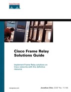
This section presents a case study of a Frame Relay SVC network, entailing full configuration examples on Cisco routers. Many of the configuration commands introduced in this chapter are configured and demonstrated in this case study. Figure 11-2 shows the network diagram of the setup used for this case study.
A STDX 3000 Cascade switch is used in the lab setup for the configuration examples in this section. The examples are focused mainly on the configuration of a Cisco router as a Frame Relay DTE device on the Cisco IOS software. A SVC connection is set up between the Cisco routers via the Frame Relay switch.
NOTE
The configuration model used in these examples is similar to production networks set up with commercial Frame Relay switches capable of supporting SVCs.
Figure 11-2 shows the Frame Relay SVC network setup used for the configuration examples in this section.
In the network diagram depicted in Figure 11-2, both routers R1 and R2 are configured as Frame Relay access devices (DTEs) establishing a SVC connection to the service provider Frame Relay switch. In Figure 11-2, the service provider's Frame Relay switches are fully meshed to minimize network downtimes due to failure of any core switch. Example 11-10 shows the basic configuration setup of R1 and R2 in Figure 11-2. The values of the CIR, Bc, and Be parameters for setting up a Frame Relay SVC are usually supplied by the Frame Relay SVC service provider.
Example 11-10. Basic Configurations of R1 and R2 in Figure 11-2
! R1
<output omitted>
interface Serial4/0
 no ip address
 encapsulation frame-relay
 frame-relay lmi-type ansi
 frame-relay svc
!
interface Serial4/0.1 point-to-point
 ip address 172.16.1.1 255.255.255.0
 map-group cisco_svc
!
map-list cisco_svc source-addr E164 123456 dest-addr E164 654321
 ip 172.16.1.2 class r1 broadcast ietf
!
map-class frame-relay r1
 frame-relay cir 64000
 frame-relay bc 8000
 frame-relay be 8000
 frame-relay mincir 32000
 frame-relay holdq 32
 frame-relay idle-timer 90
 no frame-relay adaptive-shaping

! R2

<output omitted>

interface Serial4/0
 no ip address
 encapsulation frame-relay
 frame-relay lmi-type ansi
 frame-relay svc
!
interface Serial4/0.1 point-to-point
 ip address 172.16.1.2 255.255.255.0
 map-group cisco_svc
!
map-list cisco_svc source-addr E164 654321 dest-addr E164 123456
 ip 172.16.1.1 class r2 broadcast ietf
!
map-class frame-relay r2
 frame-relay cir 64000
 frame-relay bc 8000
 frame-relay be 8000
 frame-relay mincir 32000
 frame-relay holdq 32
 frame-relay idle-timer 90
 no frame-relay adaptive-shaping
NOTE
This configuration example only focuses on Cisco IOS configuration commands on the Cisco router operating as the DTE device. The configurations for the commercial Frame Relay switch used in the lab are not shown.
In the configuration example shown in Example 11-10, note that the frame-relay svc command is enabled under the main interfaces of both R1 and R2. This command enables Frame Relay SVC for all subinterfaces configured under the physical interface. The Frame Relay subinterfaces configured on both R1 and R2 are associated with the map list named cisco_svc via the map-group map-list-name command. A meaningful map list should be used to identify the particular connection established.
The map-list global configuration mode defines the addressing or numbering plans assigned by the service provider. Both X.121 and E.164 addressing plans are supported by Cisco IOS. Observe that the destination E.164 address configured on R1 coincides with the source E.164 address configured at R2 and vice versa. This mapping must be configured correctly at the local peer in order to inform the Frame Relay switch of the destination peer with which it would like to connect. RFC 1490 encapsulation is also used, as shown in the ietf keyword.
Under the map-list configuration command mode, the remote destination's network layer address is mapped to a Frame Relay map class where the call parameters for the particular connection are defined. The switch negotiates the call setup using the parameters specified in the Frame Relay map class. In our example, the CIR, committed burst size, excess burst, minimum CIR, and the output hold queue are specified.
Finally, the frame-relay idle-timer command is used to reduce the idle time allowed on the SVC from the default 120 seconds to 90 seconds.