2.8. Current Physical Viewpoint
Before You Reached Here ...
![]() Easiest: You’ve looked at further refinements of the data flow model in Chapters 2.6 More on Data Flow Diagrams and 2.7 Leveled Data Flow Diagrams. Now we add a viewpoint to those refinements. After you read this chapter, you will return to Piccadilly to build a current physical model of its operations.
Easiest: You’ve looked at further refinements of the data flow model in Chapters 2.6 More on Data Flow Diagrams and 2.7 Leveled Data Flow Diagrams. Now we add a viewpoint to those refinements. After you read this chapter, you will return to Piccadilly to build a current physical model of its operations.
![]() More Difficult: You’ve arrived here from Chapter 1.3 What About the Business Data? This chapter will give you a viewpoint that you’ll use when you continue to model Piccadilly’s business.
More Difficult: You’ve arrived here from Chapter 1.3 What About the Business Data? This chapter will give you a viewpoint that you’ll use when you continue to model Piccadilly’s business.
![]() Most Difficult: The viewpoint chapters are not part of your trail as you have elected to do the Piccadilly Project without our help. However, you may decide to review this chapter. The next part of the project to be modeled is the whole organization, starting in Chapter 1.4 The Piccadilly Organization. The “Strategy” heading in that chapter explains our approach for analyzing the business, and it involves the current physical viewpoint. If you wish, read this chapter to see how we do it.
Most Difficult: The viewpoint chapters are not part of your trail as you have elected to do the Piccadilly Project without our help. However, you may decide to review this chapter. The next part of the project to be modeled is the whole organization, starting in Chapter 1.4 The Piccadilly Organization. The “Strategy” heading in that chapter explains our approach for analyzing the business, and it involves the current physical viewpoint. If you wish, read this chapter to see how we do it.
![]() Promenade: The correct route for you to get here is from Chapter 2.3 A Variety of Viewpoints. If you are reading the Textbook sequentially, this chapter will still make sense, but for your purposes, it’s easier to follow the trail.
Promenade: The correct route for you to get here is from Chapter 2.3 A Variety of Viewpoints. If you are reading the Textbook sequentially, this chapter will still make sense, but for your purposes, it’s easier to follow the trail.
What Is a Current Physical Model?
A current physical model is a replica of the users’ existing operation. We use the terms “current” because the model shows the system as it exists at the moment, and “physical” because the analyst portrays the actual procedures and devices used to implement the system. When you present a picture of the system that the users can easily recognize, you break down at least one barrier to your communication with them.
In Figure 2.8.1, the model intentionally shows implementation characteristics, as the names are meant to be recognized by the users. The names in the bubbles are the device or process names as the users know them. Data flow names are, in most cases, the users’ names for the documents and packets of information that move around the office.
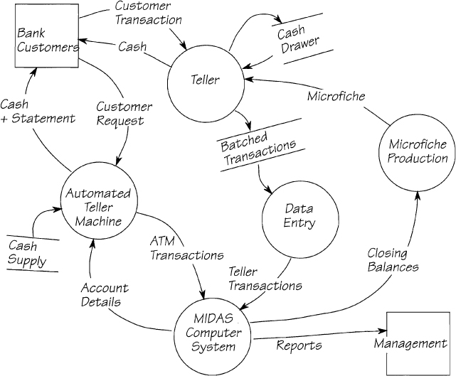
Figure 2.8.1. The current physical model for part of a bank’s operations. This model depicts the system as you would see it if you visited the bank.
Why Build a Current Physical Model?
There is a paradox: The current physical model is a model of the system that you are about to replace. Why spend valuable time doing this? Why, for example, include microfiche production in a model when the intention is to replace it with an on-line terminal for the teller?
There is an old joke about a tourist who stops his car on a country road and asks a farmer how to get to a certain town. The farmer chews on it for a while, and eventually replies, “You can’t get there from here.”
The joke makes use of an absurdity: You can always drive from one town to any other provided they are on the same land mass. However, systems analysis is different. You are trying to find the “perfect” requirements for the system. At the beginning of an analysis project, without information about the users’ business, you have very little chance of finding your way to the perfect requirements. This time, you may not get there from here.
Let’s go back to the example in Figure 2.8.1. We mentioned above that the bank intends to replace microfiche and give the teller an on-line terminal. Why not specify the terminal right away? Well, how will you know what data the teller needs if you do not know what data he uses at the moment? By including the microfiche in your current physical model, you know where to look to see the data that the teller uses. Omit it, and finding a place to start the analysis becomes more difficult.
The current physical model is not the specification of the system. It is merely a way to start the analysis. At the beginning of analysis, the users describe their business to you in a way that typically includes the mechanisms they use to get the work done. While these mechanisms are not the basic policy of the system, you build the current physical model to help you understand the existing system and to begin to gather requirements for the new system.
When you capture the system in its current form, you collect many of the new system’s requirements. Despite any bad reputation or glaring faults the current system may have, it is not totally worthless and may even have many functions that are making a positive contribution to the business. So there are some parts of the current system that must be included in any future system. You may implement them differently with new technology, but their underlying business policy, their essence, remains almost unchanged. Depicting the existing system with a current physical model is the first step toward ensuring that you include all the essential functions and essential data in your future system.
The current system may be far from perfect, but you can learn a lot from it.
Your future system must be relevant to the users’ business. That much is obvious. Your system will be relevant if it fits into the way the users do their business. Gone are the days when you could put together whatever system was most convenient to you or easiest to build, and tell the users to take it or leave it. Building a current physical model gives you the opportunity to study and understand the way they do things now, before trying to improve them.
History is littered with spectacular failures that happened by developers’ failing to understand the current system before implementing “improvements.” In the early days of Australia, English settlers brought with them their domestic cats and dogs. Although these animals were not native to the colony, the settlers reckoned the addition of a few household pets would improve the country somewhat. What they failed to understand was that most of the native Australian birds were ground dwellers, not tree dwellers as in their former home in England. In the absence of predators, the cats and dogs within only a few years of their arrival made the ground-dwelling birds extinct. Perhaps if the settlers had understood the existing situation, they wouldn’t have introduced their “improvements.”
Gaining the Users’ Confidence
One of the most immediate benefits you notice when you build a current physical model is the positive response from the users. People always like it when others take an interest in their work. Your model, which reflects the way their business operates, confirms your interest and builds cooperation. It gives your users the opportunity to recognize and understand your models, and to verify the correctness of your analysis. Almost as importantly, during the brief physical modeling activity, the users become familiar with your analysis style, and it will be easier for them to contribute to your modeling effort.

Figure 2.8.2. The user and the analyst work together to build an identical understanding of the business.
You are not trying to gain the users’ confidence just to feel a warm glow. At some stage of the project, you will have to recommend ways to implement a new system. The users aren’t likely to have any confidence in your recommendations if you haven’t demonstrated your understanding of the existing one.
One other aspect of physical modeling is worth mentioning here. We always use data flow diagrams in our consulting business to record our interviews with users as they talk. We then show them our diagrams, talk them through the models, and confirm that we have captured exactly what they said. We solicit corrections for our misunderstandings, and continue modeling until both sides agree that the model is a faithful replica of the system under study. Then we hear the magic words, “Yessir! That’s my business!”
Defining the Context of Analysis
The overriding reason for building a current physical model is to negotiate and verify the scope of the system you are about to study. It is critical for any analysis project to correctly define the boundaries of the system. Where does it start and where does it end? It is equally critical that the users and the analysts have the same, agreed understanding of those boundaries. The context diagram, in Figure 2.8.3, for example, defines the boundaries and shows how the system fits into the outside world. This should be the first of your analysis models and should be built as soon as possible after the start of the project.

Figure 2.8.3. The context diagram for the Regional Theater Casting System. The system finds actors for parts in plays being produced for the small drama theaters around the country. The context diagram is used to negotiate the precise domain of the analysis effort.
The context diagram shows the boundary data flows that run to and from the terminators. It is these flows, and not the terminators, that define the boundaries of the system. How?
Your early interviews with the users will reveal some objects that appear to be outside the domain of study, so it is reasonable to show these as terminators. However, keep in mind that the terminator symbol really means “that part of the terminator that interacts with my system.” To know precisely which part, you need to examine the data flow.
For example, PRODUCER and ACTOR are both shown as terminators in the context diagram (Figure 2.8.3). But shouldn’t they be part of the system? Couldn’t the producer auditioning an actor be considered a necessary component of a casting system? In this case, no. The diagram clearly shows you that the audition takes place outside the system. The system tells the producer about the audition with the data flow AUDITION SCHEDULE, and the PRODUCER DECISION data flow advises the system of the result.
On the other hand, actors come in to the Regional Theater Casting offices to apply for a part. In this case, their bodies are physically inside the system, but the data flow ACTOR’S REGISTRATION determines how much of a role they play in it (no pun intended).
Note the flow ADVERTISING INSTRUCTIONS going to the MEDIA. Everything to do with the advertising, such as writing the copy and designing the layout, happens inside the system; otherwise, this flow would not be in the context diagram. See what a precise definition of the context this is. Without this flow in the context diagram, you would have to rely on a statement such as, “The system includes advertising.” What does that mean? Does it mean that the system is expected to print the advertisements? Or does it mean that someone decides what to advertise and what to send to a production house for the finished ad? Here, the context diagram is saying, “Every activity that contributes to the data in the flow ADVERTISING INSTRUCTIONS is included in the domain of analysis.” By knowing what those data are, you know what the activity is. If the activity to be studied were different, the boundary flow would be different.
The boundary data flows also define the system’s stored data. In the early part of the Piccadilly Project, you built a preliminary data model using the context diagram as input. Later in the project, you will see how you can partition this diagram in different ways depending on what you need to see. It will prove to be very useful.
It is vital that the users, management, and project team all agree on the context of the project, and agree as early as possible. Otherwise, you run the very real risk of analyzing the wrong part of the users’ business. The area to be analyzed is the part of the business that the user has some need or desire to change, and any other areas in contact with the changes.
There are two types of functions: those to be changed, and those to be computerized. The new system may result in the computerization of manual processes, or the reimplementation of an existing computer system. For your analysis to work correctly, your context must be large enough to include all those functions that have a possibility of being computerized, together with the manual functions in contact with the computer system.
The context of the system in Figure 2.8.4 is everything within the dotted boundary line: Some of the analyzed functions will not be automated or changed in any way. However, analyzing them is not a waste of effort. To build an appropriate computer system, you must fully understand the surrounding processes: those processes that produce the input data so that your computer system always receives the data it expects; and those that use the computer’s output. Otherwise, you cannot be sure that you’re generating relevant information.

Figure 2.8.4. The context of the system. Note how the analysis covers a much larger area than the target of change. By doing this, you ensure that the changed functionality, probably a computer system, fits exactly into the users’ business.
If the context of study is too small, you’ll fail to take advantage of automation opportunities in the users’ business. If the context is too large, you’ll waste analysis effort. If the context is erroneously located, you’ll deliver a system that doesn’t provide the facilities needed by the end user. As any of these mistakes will result in an unsuitable future system, you need to spend the necessary effort to establish the right context.
Building a Current Physical Model
Once the context is agreed upon, then you make the first attempt to partition the system. The first breakdown, called Diagram 0, is a rough breakdown of the context. As we’ve said, the current physical model reflects the business as the users see it, so it is likely to include departments, people, devices, and so on. Consider Diagram 0 in Figure 2.8.5.

Figure 2.8.5. This Diagram 0 uses a partitioning theme that imitates the existing departments. The data flows mirror the documents and information that travel between the departments and between the company and the outside world. The users’ names are added to the bubbles to make the model easier to recognize.
There are, admittedly, some problems with this very physical model and its messy interfaces. However, its objective is to emulate reality, not to be great art. Sometimes, the systems you study are not partitioned along purely functional lines, and your diagrams may look even more untidy. It doesn’t matter. As the analysis progresses, you’ll level downward from these partitions to find a more logical system. At the moment, the diagram serves you well as a starting point.
Diagram 0 verifies the context. As you build this diagram, you’ll likely discover some details to make you alter your context diagram. This is normal and should not cause concern. Indeed, some analysts prefer to construct the context diagram and Diagram 0 in parallel, since both diagrams require similar information from the users, and one can’t be finished without the other.
Whichever way you develop your Diagram 0, it now provides you with the basis for gathering the details.
Gathering the Details
Once you are reasonably confident that the interfaces are correct, you can treat each of the bubbles in Diagram 0 as a separate system. Each process and its data flows in the diagram form the context for a lower-level study. This time, however, restrict your study to whatever happens inside that process. Analyze the process by interviewing the appropriate users, and by drawing data flow diagrams from their answers.
As you descend into the details, you’ll begin to see a more logical partitioning emerge. The partitioning at the top level is usually political, and therefore not subject to reason. At the lower level, the bubbles are more functional and reveal the true business policy. (We discussed this leveling process fully in Chapter 2.7 Leveled Data Flow Diagrams.)
How Detailed Should It Be?
The current physical model provides a common language between the users and the analyst. Therefore, you build this model as long as you need a tool to help you communicate with the user.
Remember that the model is only a stepping stone to later stages of the analysis. It is a waste of time to build a perfect current physical model containing a complete set of lower-level diagrams, together with the supporting data dictionary and mini specifications for every process. There is no need for this elaboration. You’ll be able to get what you want without all of the lower-level diagrams. We recommend that you build no more than two levels below Diagram 0, and only go that far for large systems. Collected documents can substitute for written entries in the data dictionary. Manuals of procedures and interview notes are a satisfactory substitute for mini specifications.
The current physical model should contain only as much detail as you need to gain a clear enough understanding of the system to be able to build the essential requirements model.
The objective of your analysis is to discover the underlying policy: the essential requirements. We’ll discuss this topic at some length in Chapter 2.10 Essential Viewpoint. For the moment, let’s say the essential requirements are those that are necessary for the business and are completely independent of any technology. As desirable as it may seem, you’ll have difficulty bypassing the current physical model altogether in your search for the essence. Most of the users you’ll encounter are knowledgeable about their business, but not that many of them can completely describe the abstract, essential requirements. So you are likely to include physical characteristics in your early models to allow the users to recognize their system.
How many physical characteristics you include varies enormously. It depends on the users, your knowledge of the system, and your own skill as an abstract thinker. Some users are adept at realizing that physical features are only part of the implementation and happily accept models without them. Others have trouble recognizing the essence of the system.
The physical modeling activity always ends as soon as you are able to build the essential models. Sometimes, early in the project, you are able to gather all the information you need to build essential models. Sometimes, you have to do a certain amount of current physical modeling before you and the users can see the essentials; and sometimes, having started the essentials, you need to augment your knowledge by backtracking and modeling more of the current physical viewpoint.
There are occasions when you build current physical models for a different reason. Management may need to see what the organization is doing. Recently, we were asked to consult with a medical insurance company. The company had expanded so rapidly that its managers were having difficulty keeping in touch with their own infrastructure. We worked with the staff to build a physical model of their organization. This “warts-and-all” model was used by the staff and management to see what was going wrong with their way of doing business. They were able to identify the areas in most urgent need of attention, to find duplicate and redundant procedures, and to locate the most fertile areas for further study. The current physical model is still being used as a springboard for new analysis projects.
Summary
Whether you build a current physical model depends on your users and yourself. Sometimes, the users need to see recognizable physical details in the models before they can contribute to the analysis. Sometimes, you and others on the analysis team need to build this kind of model to fully understand the business. Sometimes, very little physical modeling is necessary before you can get on with building your essential models. Your responsibility is to build as much current physical model as you need, and no more.
Trail Guide
![]() Easiest: You now have some more data flow modeling skills and a way of looking at the current system. Return to the Piccadilly Project where you’ll build models of the entire company. You’ll find this assignment in Chapter 1.4 The Piccadilly Organization.
Easiest: You now have some more data flow modeling skills and a way of looking at the current system. Return to the Piccadilly Project where you’ll build models of the entire company. You’ll find this assignment in Chapter 1.4 The Piccadilly Organization.
![]() More Difficult: We are bringing you through the viewpoint chapters of the Textbook because systems analysis is easier and clearer if you adopt a single viewpoint for each of your models. We suggest you use the current physical viewpoint in the Piccadilly Project while you are becoming familiar with the television business. The next stage of the Project is found in Chapter 1.4 The Piccadilly Organization.
More Difficult: We are bringing you through the viewpoint chapters of the Textbook because systems analysis is easier and clearer if you adopt a single viewpoint for each of your models. We suggest you use the current physical viewpoint in the Piccadilly Project while you are becoming familiar with the television business. The next stage of the Project is found in Chapter 1.4 The Piccadilly Organization.
![]() Most Difficult: You are off your trail if you are reading this, but you can find it again in Chapter 1.4 The Piccadilly Organization.
Most Difficult: You are off your trail if you are reading this, but you can find it again in Chapter 1.4 The Piccadilly Organization.
![]() Promenade: You aren’t reading this book to do the work of modeling the Piccadilly system, so don’t follow the others to Section 1. Instead, we want to show you another very different viewpoint in Chapter 2.4 Data Viewpoint.
Promenade: You aren’t reading this book to do the work of modeling the Piccadilly system, so don’t follow the others to Section 1. Instead, we want to show you another very different viewpoint in Chapter 2.4 Data Viewpoint.