2.11. Event-Response Models
Before You Reached Here ...
![]() Easiest: In Chapter 2.10 Essential Viewpoint, you have read about the essential view. Now we’ll discuss how to build event-response models that make use of this viewpoint. The idea behind event-response modeling is simple, but to use it effectively, you must understand it correctly. Read on.
Easiest: In Chapter 2.10 Essential Viewpoint, you have read about the essential view. Now we’ll discuss how to build event-response models that make use of this viewpoint. The idea behind event-response modeling is simple, but to use it effectively, you must understand it correctly. Read on.
![]() More Difficult: Strictly speaking, this chapter is not on your trail. However, event-response modeling is very important and may not be as straightforward as it seems. As you are already here, read through the chapter. If you find that you already know about these models, then skip to Chapter 1.8 Identifying Events.
More Difficult: Strictly speaking, this chapter is not on your trail. However, event-response modeling is very important and may not be as straightforward as it seems. As you are already here, read through the chapter. If you find that you already know about these models, then skip to Chapter 1.8 Identifying Events.
![]() Most Difficult: You are traveling on a trail where you presumably know about these models, so Chapter 1.8 Identifying Events is the most logical (no pun intended) destination.
Most Difficult: You are traveling on a trail where you presumably know about these models, so Chapter 1.8 Identifying Events is the most logical (no pun intended) destination.
![]() Promenade: You’re here because of the importance of event-response modeling, a strategy for building the essential requirements model. Most systems analysts use it because it is the simplest, easiest, and most straightforward method of deriving the real requirements of the system. Additionally, because events are small units of work easily recognized by the users, an event-partitioned essential model has advantages when it comes time to implement the system. Later, we’ll talk about using event-response models as the basis for estimating project effort.
Promenade: You’re here because of the importance of event-response modeling, a strategy for building the essential requirements model. Most systems analysts use it because it is the simplest, easiest, and most straightforward method of deriving the real requirements of the system. Additionally, because events are small units of work easily recognized by the users, an event-partitioned essential model has advantages when it comes time to implement the system. Later, we’ll talk about using event-response models as the basis for estimating project effort.
Building an Essential Requirements Model
A current physical model uses the physical processors, such as departments, people, machines, computers, and so on, as its partitioning theme. A rather exaggerated current physical model might look like the one shown in Figure 2.11.1.

As we’ve said many times before, basing the requirements models for a system on the current implementation is not a great idea. The way the business is currently operating conceals the essential requirements for the system. So if the internal mechanisms of the system aren’t the best place to look for these requirements, you must look elsewhere. Looking outside the system may be rewarding.
Systems exist to provide services to the outside world. The services have one thing in common: They are provided as a response to some event that takes place outside the system. For example, in Figure 2.11.2, when customers decide they want a taxi, they do it outside the context of the taxi system. When they decide to make a payment for their account, again they make their decision outside the system’s context. Such a happening outside the system is called an event.

Figure 2.11.2: The context diagram shows the system’s connections to the outside world. By inspecting the connections, you can discover the system’s services. The outgoing data flows indicate the taxi company’s services to its customers and cabs. The system uses the data in the incoming data flows to provide these services.
Events
We are concerned with events because they provide us with a method for making a logical breakdown of the system. This method is called event partitioning. To make it, you must focus on what happens in the world outside your analysis study. Specifically, you are looking at the happenings, or events, that take place in the terminators. Your system knows that an event has occurred because it receives a data flow from a terminator. The system has a unique response to each event.
Each event produces a unique data flow. It must be unique because the system can determine which event has happened by the data content of the flow. Only by recognizing the event can the system produce the correct response.
Events are given a unique name. For example, the event shown in Figure 2.11.3 is called Customer wants a taxi. The name of the event provides you, the analyst, with an indication of what the response should be. When the name is descriptive, it provides you with a relevancy check when you must search through a system to discover the appropriate response.
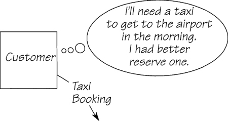
Figure 2.11.3: An event happens outside the system. The system has no control over when or why it happens, but it knows that the event has taken place because the event produces a data flow.
Identifying the Event-Response
An event response is a system’s predetermined reaction to an event. It is a collection of all the actions that respond to the event, regardless of where they happen in the current implementation. Ignore processor boundaries. If a process or data store anywhere within the system is part of the reaction, include it in your event-response model. In the example in Figure 2.11.4, the system has predetermined actions that are triggered by the arrival of the data flow TAXI BOOKING.
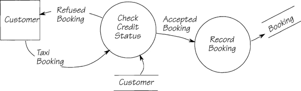
Figure 2.11.4: The event-response model for the event Customer wants a taxi. The system identifies its response from the incoming data flow TAXI BOOKING. The response includes all the processes and data needed to react to this data flow.
Note that in the event-response model in Figure 2.11.5 (or in any other event-response model), the response is bounded by terminators and data stores. A terminator supplies data to the system, but the behavior of the terminator is outside the control of the system; you cannot predict when it will send its data. Similarly, if the system sends a data flow to a terminator, you cannot predict how long the terminator will take before it reacts. In the same way, when a data item is stored, you probably cannot predict how long it will remain there until it is retrieved. Both the terminator and the data store are time-delaying mechanisms.

Figure 2.11.5: The event-response model for the event Cab owner submits account vouchers. The response begins when the account vouchers arrive, and ends when the system has recorded the data and has sent the account payment to the cab owner.
The significance of time-delaying mechanisms surrounding the event-response is that the response itself takes place in its own discrete and continuous period. When the system is responding to an event, processing continues until the data flows reach the final data stores or terminators. Just as you ignore processor boundaries, you also ignore delays normally associated with crossing processor boundaries (waiting for an available operator to key in data, the time taken to print information, and so on).
Simply put, when a data flow enters the system, the event-response processing continues until the system has accessed all of the data stores concerned with the response and, whenever necessary, has sent the appropriate data flows to the terminators.
Identifying Temporal Events and the Time Trigger
So far, the events discussed have all been external. External events start outside the system at a terminator and trigger the system’s response with a data flow. There is another type of event-response called a temporal event because it is triggered by the arrival of a predetermined time. For example, let’s say that on the fifteenth of each month, the system produces its monthly accounts. The arrival of the fifteenth day is the event. Its response is shown in Figure 2.11.6.

Figure 2.11.6: The response to the temporal event Time to produce monthly accounts. The system gathers stored data, processes the data, and then communicates with the outside world.
Another way for a temporal event to be triggered is by the passage of time in relation to stored data. For example, the dispatcher always calls for a taxi ten minutes before the booking time to give the selected taxi time to arrive at the customer’s pickup point. So an event happens whenever it is ten minutes before a recorded booking. The system’s response to this event is shown in Figure 2.11.7.

Figure 2.11.7: The model for the temporal event Taxi booking becomes due. There will be another external event happening shortly when nearby taxis radio their locations.
Temporal event-responses begin when it is time to provide a service. The processing for the response starts inside the system, usually with a process accessing stored data. The event-response finishes when the system sends one or more data flows to the outside world.
Finding Events
The context diagram is the place to start identifying events, since it shows all the data flows crossing the system boundary and since all these flows are, one way or another, connected to an event-response. The best strategy is to first identify all external events. When a data flow enters the system’s context, it does so because an external event has occurred. Any input data flow is associated with just one external event. This means that by inspecting the incoming data flows, you can determine all of the external events that affect your system.
Some external events simply store the incoming data. Some, as part of their response, send data to the outside world. In other cases, responses to external events generate more than one outgoing flow. So each of your external events may be linked to one or more of the outgoing flows.
What about the output flows that are not linked to an external event? These are the products of temporal event-responses. Any flow whose name suggests a periodic production (for example, REMINDER and APPOINTMENT SCHEDULE in Figure 2.11.8) originates with a temporal event-response. By a process of inspection and elimination, you should be able to attribute the boundary data flows to their respective events.
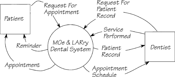
Figure 2.11.8: The context diagram for the MOe & LARry Dental system. Each of the data flows is a part of an event-response. How many events can you determine from this diagram?
All of the data flows in the context diagram must be accounted for. They either trigger a response or are the result of an event-response.
Naming Events
After you have found all the events, you need to give each event a name. The name must reveal the nature of the event, and thus give a clue as to the expected response. For example, Patient gets a toothache describes an event, but it gives no indication of what it has to do with our system. Patient needs appointment not only tells you and your reader what the event is, but also what kind of response the system must make.
A guideline for naming external events is to use this template:
• External event name = Terminator name + reason for the data flow
For example, using this template, the event that produces the data flow REQUEST FOR PATIENT RECORD is called Dentist needs patient record. A template for naming temporal events is
• Temporal event name = Time to + action that must be taken
In the dental system, this template gives you a temporal event called Time to produce appointment schedule.
Compiling the Event List
Once you have named the events from the context diagram, the most convenient way of keeping track of them is to use an event list. This list is simply an inventory of all the events to which the system responds. As the analysis progresses, you will find such a list useful for recording which events have been modeled, and which remain to be done. You will also find that the list helps you to categorize the events into groups by those that have a similar response. This can save you much work later if you need to copy the pattern of the response from one event-response model to another.
Here are the events that were derived from the context diagram in Figure 2.11.8 for the MOe & LARry Dental system:

The numbers assigned to the events are arbitrary and do not indicate any kind of priority or time sequence. The associated data flows are listed to help you to account for all the events. The (in) or (out) following each data flow name indicates the obvious: whether the flow is into, or out of, the system. This notation makes it easier to account for all of the flows.
The purpose of the list is to help you keep control of your model. Some systems have several hundred event-responses, and controlling the complexity of the models for these systems can be difficult.
For each event in the event list, build an event-response model by linking all the processes that respond to the event. This task is simpler if you keep in mind that an event is either an external or a temporal event. The event-response follows the pattern for that type of event. Let’s look at these patterns.
Seeing the External Event-Response Pattern
The external event is some happening in the outside world. The event-response starts when the system receives a flow from a terminator. The response ends with a combination of flows to and from data stores and/or flows to terminators (Figure 2.11.9).
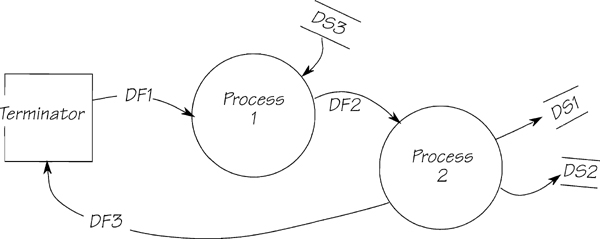
Figure 2.11.9: An external event-response pattern. The incoming data are processed, then stored. The data flow back to the terminator (DF3) is a receipt for the original message (DF1). This receipt flow is not always present in external event-responses. Even if there is an outgoing flow from an external event-response, it does not necessarily go back to the original terminator.
Typically, the incoming data go through a series of checks and validations, and are then added to a data store. For example, in the taxi system, the customer was checked to see that he was not a known bad payer, and then the request was added to the BOOKING store (Figure 2.11.4). Sometimes, the system acknowledges the initial message by sending some data back to the terminator (for example, in Figure 2.11.5, the ACCOUNT PAYMENT is sent in response to the ACCOUNT VOUCHERS).
The external event-response usually includes some combination of storing data, and/or referencing previously stored data. Use the two patterns shown in Figures 2.11.9 and 2.11.10 as a guide. All external event-responses are variations on these themes.
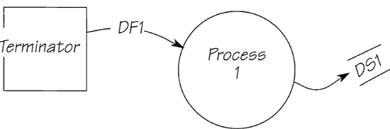
Figure 2.11.10: Sometimes, the external event-response can be as simple as this. The data flow is stored without any access to existing stored data, and no outgoing flow is generated.
Seeing the Temporal Event-Response Pattern
A temporal event is triggered when it is time to do something, or when a predetermined time occurs. Temporal events have stored data at one end of their chain of bubbles, and a terminator at the other.
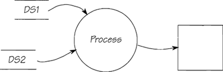
Figure 2.11.11: The usual pattern for a temporal event-response is to collect data from the system’s stored data, then process and send the data to the outside world. Sometimes, temporal event-responses store data.
Temporal events tend to be relatively simple. In this example (Figure 2.11.11), there is only one bubble, which is quite common, as most temporal events are simply reporting on stored information.
Now that you know what the models look like, let’s build an event-response model using the dental system example.
Using the Current Physical Model to Build the Essential Model
In Chapter 2.10 Essential Viewpoint, we discussed the need to model the system from the point of view of the business policy in order to find the essential requirements. Breaking the system into event-responses is only the first step toward finding these requirements. Now we have to find the essential event-response and build the model.
The information needed to build an essential model may come from several sources: the current physical model (if you built one), interviews with the users, sample reports, observations of the work as it is done, job descriptions, sample input documents, existing computer systems, and so on. Let’s start by looking at the current physical model as a source of event-response information.
The way to use this model is to link the processes that make up the system’s response to each event. This usually involves following the trail of processes through several diagrams. For example, Figure 2.11.12 shows the model that results from joining the processes that respond to event 3 Dentist needs patient record in the MOe & LARry Dental system.
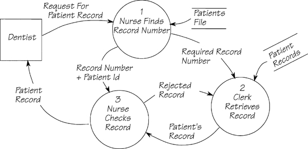
Figure 2.11.12: This event-response is a faithful recording of the way the current implementation responds to the event Dentist needs patient record. The dentist knows only the patient’s name and address, so those items are part of the request data flow. The nurse looks up the patient’s record to find the RECORD NUMBER because the filing clerk, who works in a different department, can only find the records by number. Since the nurse doesn’t trust the clerk, the nurse checks the record to ensure the clerk has located the correct patient record.
Whenever you use the current physical model as input to building your event-response models, you’ll probably include processes extracted from several diagrams. Then you’ll notice a major advantage of event-response modeling: You have a cohesive unit that is small enough to examine in detail. It now becomes far easier to assess whether a process is a duplication, redundant, dependent on the current implementation, or part of the essential policy of the system. If any processes or data are not part of this policy, you must eliminate them.
Modeling the Essential Processes and Stored Data
The essential stored data and the essential processes exist to support the system’s business policy, and they are so closely linked that we can consider them together.
If the system stores data, naturally enough, the data must come into the system via an incoming boundary data flow. In other words, there is an external event response that stores the data in essential memory. On the right-hand side of Figure 2.11.13, you see a temporal event-response retrieving the essential stored data. The essential rules apply: If the data are stored, the data must be essential and needed for the services provided to the outside world. Data are essential only if referenced by at least one other event.
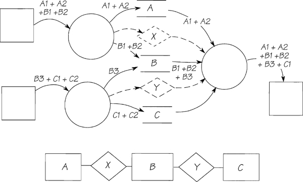
Figure 2.11.13: An event occurs and the resultant data flow enters the system. The incoming data flow contains A1, A2, B1, and B2. These are named to suggest the entities that would hold that data. The event-response stores the A data in the A entity, stores the B data in the B entity, and creates the relationship X. (The relationship is shown dotted only to suggest its creation and use. We do not advocate showing relationships in event-response process models unless the relationship contains data.) The second external event-response stores B3, C1, and C2, and creates relationship Y. The temporal event-response retrieves the stored data, processes the data, and sends the resultant data flow to the outside world. The data model to support this fragment of the system is shown below the event-responses.
The data flows to and from the terminators (the boundary flows) are initially considered to be essential flows. The reason for this is that when the context of the system is agreed, the boundary data flows are the data provided by or needed by the system’s services; that is, the terminators provide or expect these flows.
You’ve seen how the event-responses store or retrieve essential stored data. A problem can arise if an external event-response stores data from a boundary data flow, and no other event-response references that data. If this happens, you may not be able to change the actual physical data (the terminator will probably continue to send the data as always), but you must adjust the definition of the incoming boundary data flow to reflect the data that the system really needs. The new implementation of the system will ignore the unwanted items.
Developing the Event-Response Data Model
While considering the data being stored and retrieved by event-responses, you can also consider the data associated with each event-response. You have already isolated the essential processes necessary for one event-response. Now do the same for the essential data. To illustrate, let’s look at a typical example of how an event-response uses stored data. The event-response model for event 1 of the MOe & LARry Dental system, Patient needs appointment, is shown in Figure 2.11.14.
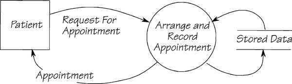
Figure 2.11.14: An intermediate version of the event-response model for the MOe & LARry Dental system. The stored data are undetermined as yet, and so are shown simply as STORED DATA.
In the figure, there are some things to consider:
• The data flows REQUEST FOR APPOINTMENT and APPOINTMENT are boundary data flows; they enter and leave, respectively, the context of the system.
• The data added to STORED DATA must be part of REQUEST FOR APPOINTMENT or be calculated by the process; the data can’t come from anywhere else.
• The data content of APPOINTMENT must come from STORED DATA, or from REQUEST FOR APPOINTMENT.
As REQUEST FOR APPOINTMENT initiates this event-response, let’s examine its data content:
Request For Appointment = Patient Name
+ (Required Date)
+ (Required Time)
+ Dentist Name
+ {Required Service}
The date and time are optional, as some patients will take whatever appointment is available. The patient designates a dentist—either Moe, Larry, or Curly—and indicates if he requires certain serious services.
What happens to the data? The patient’s name is used to reference an existing patient or, if this is the first visit, to record a new name. This means there must be an entity in essential memory called PATIENT. There is no other information in the data flow about a patient, so the only thing we can say now is that there is an entity called PATIENT with an attribute PATIENT NAME.
The next two items in the data flow are used to negotiate an appointment with the designated dentist. If the patient requests any services, they must be related to the appointment. Using the information from the data flow, you can construct a model of the data used to support this event-response. The result is shown in Figure 2.11.15.
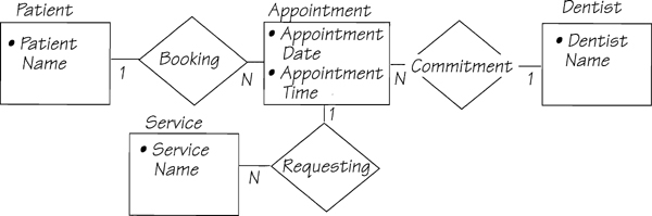
Figure 2.11.15: This event-response data model is built from the data flows connected to the event Patient needs appointment. The data elements are all attributed to the appropriate entities.
Now let’s examine the outgoing data flow:
Appointment = Patient Name + Dentist Name + Appointment Date
+ Appointment Time
All of the data in this outgoing flow can be retrieved from the data model (Figure 2.11.15), so it confirms our view of the stored data.
In the intermediate version of this event-response (Figure 2.11.14), we used the data store STORED DATA temporarily until we could identify the real data. Now that you know what the essential data are for this event-response, you can replace the temporary STORED DATA with stores that have the same name as the entities in the later version of the event-response data model. If you had already built a first-cut data model, you could use it to help you build the detailed event-response data model.
The event-response model shown in Figure 2.11.16 uses the stored data that you have determined to be essential. When your event-response model uses only essential data and shows only essential processes, then you have captured the real requirements. However, it is sometimes difficult to know if all the processes and data are essential. The following discussion gives some hints on building the essential viewpoint.

Figure 2.11.16: The final version of the essential event-response process model. The data stores are the entities from the data model. All the data model attributes are available to the process.
Refining Event-Response Models
When you build an event-response model directly from the current physical model, it may contain some implementation-dependent processes and data. The following types of processes are suspicious, and you can usually eliminate them from your essential requirements:
1. Audits verify that a process produces the correct result. Audits are built into systems because the processors used to implement the system are imperfect; they make mistakes, are dishonest, or whatever. However, the essential requirement eliminates all processor technology, and so eliminates all errors that can be made by the processors. Thus, there is no need for audits to check the processors.
2. Edits check the validity of data flows that travel from one processor to another. As you are ignoring processor boundaries, you can leave this kind of edit out of your essential event-response model. However, it may be necessary for the system to edit data it receives from the outside world, because you cannot influence the terminators, which are outside your context of study. So it is necessary to include “border guard” edits as the first line of defense. (Just as a border guard may check your passport as you leave a country, you may need to install a border guard edit to check a flow’s validity.)
3. Transporters are processes that move data from one processor to another, for example keypunching, scanning, or bar-code reading. These processes exist only because of the implementation; there is no essential policy involved.
4. Translators are processes that make the output from one process understandable to another; for example, an analog to digital conversion, or the printing of a report that is used inside the system’s context. These processes are not part of the policy; they exist merely because of the way the system happens to be implemented.
5. Backups are not needed. By removing the technology, you remove the potential for failure, and hence the need for a recovery method.
If you are in doubt about a process, try decomposing it into its primitive components. You’ll find it a lot easier to separate essential and implementation processes when they are at their lowest level.
It may seem radical to throw out processes that normally make up a large portion of most systems. However, keep in mind you are trying to do two things: You are trying to find the essential requirements for the system, and you are eliminating anything that could influence the future implementation of the system. Besides, you aren’t changing the current physical—that view still exists. You are merely taking a different view of the same system. Later, once you have a complete picture of the requirements, it will be time to build a view of the new implementation.
Eliminating False Data Stores
A false data store is a data store that is part of the existing system for some reason connected to the implementation. Because they are invented for nonpolicy reasons, you should eliminate false data stores from your event-response models. Take for example, the event-response to Cab owner submits account vouchers shown earlier in Figure 2.11.5. When the processes were brought together, we intentionally ignored the processor boundaries. Now let’s redraw the model to show the two different people who are involved in processing this response (Figure 2.11.17).

Note that in this example, the false data store (Ringo’s in-tray) doesn’t represent the end of the response to an event. The in-tray owes its existence to the current implementation that uses people, and the person in this case has a problem working fast enough to keep up with demand throughout the day. This false data store does not contribute to the policy of the system and should not be included in the essential event-response model. Similarly, files in which the input is batched before further processing are false. They are there for efficiency reasons only. As you do not yet know the future implementation, you don’t need to include these batch files.
However, be careful that you do not eliminate files when there is a genuine reason for batching data. For example, there are many event-responses for which it is necessary to collect data for a time before processing it further. For example, if company policy required the account payments in Figure 2.11.17 to be made once a month, the system would need to store the vouchers until it was time to process the payments. While that situation would make the in-tray necessary, it should be renamed to reflect the essential purpose of the data, rather than the implementation.
Refining an Event-Response Model: An Example
Let’s continue with the dental system example to show how to refine an essential event-response model. Consider the event-response model for the event Dentist needs patient record, repeated in Figure 2.11.18. Keep in mind that it was built from the current physical model by bringing together all the processes that respond to an event. Which processes do you think are there only because of the way the system happens to be implemented?

Figure 2.11.18: The event-response for Dentist needs patient record. These three processes were taken from the current physical model, and some of them are implementation dependent. What are the essential processes and data?
Let’s start with the PATIENT RECORDS data store. This store is created in another part of the system and is kept in record-number sequence. Record numbers are controlled by the filing clerk who tells the nurse whenever a new number has been assigned. The nurse then adds the record number to the PATIENTS FILE in the dentist’s office.
Whenever a dentist requires a patient’s record, he asks for it using the patient’s name (and, if necessary, address). The nurse has to look up the PATIENTS FILE, find the RECORD NUMBER, and give it to the filing clerk for retrieval of the patient record. The patients’ records are stored in record-number sequence because that happens to be convenient for the filing clerk. The nurse’s translation of name to record number is only necessary because of the implementation. If the data were stored in a manner that allowed it to be accessed by patient name and address, the translation step would be eliminated.
The filing clerk employed in this office is paid the minimum wage, and is prone to making errors. The nurse always checks that the clerk has retrieved the correct PATIENT’S RECORD. However, if you take the essential view, every process must work correctly (there is no technology to go wrong), and it cannot produce the wrong record.
So it appears that the two processes done by the nurse are there only because of the existing implementation, and can probably be eliminated. However, before you make them disappear, consider whether a process is doing any storage or retrieval of essential stored data. Let’s look at the definitions:
Request For Patient Record = * The address is supplied when there is a possibility of several patients with the same name *
Patient Name
+ (Patient Address)
Patient Record = Patient Name + Patient Address
+ {Visit Date + Visit Time
+ {Service Identification}}
By attributing the data elements from these two data flows, you can derive the event-response data model shown in Figure 2.11.19.
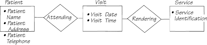
The essential purpose of the event-response is to use the incoming data flow to retrieve information about the patient. There is no record number in the incoming data flow, nor in the essential data model. The record number exists for the convenience of people who are not trusted to read names. In other words, someone in the past has chosen to use these people as the implementation, and process 1 exists only to support that choice; there is no policy attached to that bubble. As you are modeling the essential processes and not the current implementation, you can eliminate process 1 from your essential model.
You can eliminate the audit process (bubble 3) because it checks what a previous process has done. However, there is no essential requirement for a process to make errors, so there can be no essential requirement for a process to check for errors. Process 3 is also banished. You are left with the model shown in Figure 2.11.20. Note that you could have started with the essential data model and worked backward from there to build this essential event-response process model.
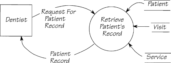
Figure 2.11.20: This is the essential event-response process model for the event Dentist needs patient record. The physical data have been replaced by the essential equivalent, and all implementation-dependent processes have been removed.
Mid-Point Summary
Before going on to practice building some event-response models, let’s review what we have. A summary is presented in Figure 2.11.21.

By now, you have the idea of essential event-response models, and it’s time for you to build some for yourself.

Exercise 1: Dentist Performs Service
The event list shows event 4 Dentist performs service. Build the essential event-response data and process models for this event. The definition of the input data flow is
Service Performed = Patient Name
+ {Service Identification}
+ Visit Date
Exercise 2: Time to Produce Appointment Schedule
Fifteen minutes before a dentist is due to arrive at the office, the receptionist goes through the appointments and makes up the dentist’s appointment schedule. The schedule lists what a dentist is doing that day. Build the essential event-response process and data models for event 5 Time to produce appointment schedule. Write a data dictionary entry for the data flow APPOINTMENT SCHEDULE.
Discussion: The Essential Data Model
By now, you have several event-response data models, with the same entities appearing in several of the models. You can consolidate the various event-response data models to form a system data model by connecting the models via their matching entities. The partial data dictionary for this model is
Appointment = Appointment Date + Appointment Time
Dentist = Dentist Name
Patient = Patient Name + Patient Address + Patient Telephone
Service = Service Identification
Visit = Visit Date + Visit Time
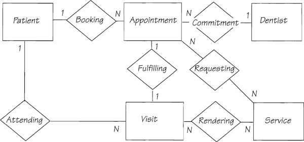
Figure 2.11.23: The system data model for the MOe & LARry Dental system. All of the entities and relationships were originally part of the event-response data models that you’ve studied.
Our knowledge of the event-responses means we can add the correct cardinality to the data model. Naturally, if you had had this data model in the beginning (or if you peeked ahead and saw it), the event-response process models would have been easier to construct. Figure 2.11.24 shows how each event-response uses part of the system data model.
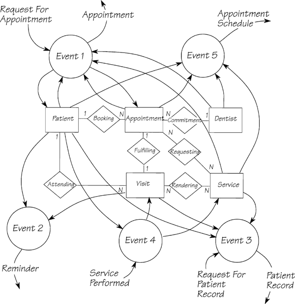
There is no one best approach to building the essential model. Our preferred way of working is to construct a series of event-response process models, together with their associated event-response data models. The reason we take this approach is that building a system data model to cater for all of the details of the events is too confusing because the scope is too large to focus one’s attention on the details. The event-response data model provides a way of focusing on the minute details of the data for one event. However, we can have the best of both worlds by amalgamating the event-response data models into one system data model (ideally, with a CASE tool to manage it). Another way to get started is to build at least a high-level version of the system data model first, then confirm it with the essential process models. This data model is useful as an inter- or intra-project communication tool. Either way works, so we have included both approaches in this book.
Discussion: Life in the Fast Lane
Now you know the complete (and laborious) way of arriving at the essential event-response process and data models. You have seen how an event-response is modeled as it exists in the current system and then refined to leave only the essentials. However, it doesn’t always have to be done that way. If you have enough knowledge about the system, you can shift up a gear or two.
Once you are comfortable with the event-response modeling approach, you can build essential models with a very abbreviated current physical model phase. The most minimal approach is to start the essential event-response models without any current physical modeling at all. If at any stage you have trouble determining the essential response, then you simply build some of the current physical model before resuming your essential approach.
The suggested fast-lane approach* uses these steps:
*McMenamin and Palmer refer to a similar approach called “blitzing” in their book, Essential Systems Analysis (see the Bibliography).
1. Build the context diagram during initial interviews with the users.
2. Use the data flows in the context diagram to determine the events. There must be an event-response to account for every data flow. Add each event, together with its associated data flows, to the event list.
3. Alternatively, if your users find it easier to identify events without the context diagram, list the event, then add the associated flows to the context diagram.
4. For each event, ask, “What event happens if this event does not happen?” For example, Customer pays is one event. Customer does not pay within the allotted time is another. Add any resulting events to the list and new flows to the context.
5. For each event,
• Interview the users about the responses to the event and build a one-bubble essential event-response process model (also known as an essential activity model). Include only the essential processes and data.
• Draw the event-response data model.
• Write the mini specification for your essential activity model.
• If the process is too complex for one mini specification, use leveling to build a low-level model. Then, write a mini specification for each process in the low-level model.
• If you have trouble building the essential models, build a physical model of the current system’s response to the event. Do only as much physical modeling as you need to understand the event-response well enough to abstract the essentials.
6. Do a CRUD check (more about this below) to test your context diagram and to discover missing events.
Identifying Custodial and Fundamental Processes
Our colleagues Steve McMenamin and John Palmer (see the Bibliography) have classified activities carried out by a system into two types: custodial and fundamental. A custodial activity maintains the system’s essential memory. For example, the response to an event such as Customer changes address is part of the system only to keep the system’s stored data current. In other words, this activity is one of the custodians of the system’s data.
A fundamental activity, on the other hand, is one of the key reasons for having the system. For example, we might have constructed the system to send invoices to our customers and to accept their payments. These fundamental activities don’t merely maintain the stored data, they are the reason for having it in the first place.
Sometimes it is difficult to differentiate between fundamental and custodial activities, and most event-responses are a mixture of fundamental and custodial activities. The reason for introducing this terminology is that certain events, which are mainly concerned with custodial activities, are sometimes hard to discover because users don’t think to tell you about them. Your CRUD check, as we’ll discuss in a moment, will help you to discover these missing events.
Performing the CRUD Check
CRUD is a mnemonic for create, reference, update, and delete. The CRUD check verifies that you have identified every data element needed by every process within the context of study, and consequently all the events, and that all your event-response models are functioning correctly.
In other words, there must be enough event-responses so that each attribute of stored data is CRUDed. At least, that is the principle. However, beware that some attributes will not be updated, and some may never be deleted, but all are created and retrieved. Missing CRUD actions for an attribute means that you may not have captured all the event-responses or that you may have some redundant data. Take, for example, the attributes of the APPOINTMENT entity in the MOe & LARry Dental system. There is an event to create them, Patient needs appointment, and an event to reference them, Time to produce appointment schedule. However, they are not updated, nor are they deleted. This means that we have forgotten two events: Patient changes appointment and Patient cancels appointment. Typically, you will add these custodial events to the list, build the event-response models, and inspect them carefully to see if other essential data are needed.
The CRUD convention says that every attribute in the data model must be created and referenced, and some will be updated or deleted.
As well as there being enough events to install the system’s stored data, there must be enough data to support the events that retrieve data. Any data element that is part of an output boundary data flow should be an essential stored attribute or should be derivable from essential data. Any data element that is used by an event-response must either be an attribute of an entity or relationship, or it must travel into the system through a boundary flow.
Beware that some attributes may be CRUDed by more than one event-response, so your audit should ask, “Are there any other conceivable uses of each attribute that have not been covered by one of the event-response models?” For example, in the MOe & LARry Dental system, the events Time to send appointment reminders and Dentist needs patient record both reference VISIT DATE. However, the references are for different reasons. The former is making a decision about whether it is now time to send a reminder to the patient, the latter is supplying the dentist with historical information about the patient.
Use the attributes of the data model to check that all the essential processes have been modeled. Use the elements of the boundary data flows to check that all the entities have been included in the data model.
Exercise 3: Sid Edison’s Radio Repairs
Try this exercise using the fast-lane approach. The following is a statement from Sid Edison, who owns a radio repair company. Although Sid is no relation of Thomas Edison, he likes his customers to make the association. He feels it helps his image. Read through Sid’s statement on how radios are repaired at his company:
“Hi, I’m Sid Edison and I fix radios. My customers bring me their broken radios. You know the kind of thing. They play their rock music at full blast until the speaker collapses. Or they don’t like something they hear and throw the radio across the room. Whichever way it’s broken, they ask me to fix it.
“I always tell them how much I think the repair’s going to cost. I either give them a firm quote for the work, or sometimes I charge them time and materials. In that case, I give them a note that explains the cost. I never start a repair job until I get an authorization from the customer. Sometimes, the cost of the repair is more than the radio is worth. I don’t want to do the work and then get stuck with a radio the customer won’t claim.
“Most of the repair jobs are pretty straightforward, but I get some tricky ones. I always look in my file for the manufacturer’s specification just to make sure. Sometimes, I have to send off to the manufacturer for the full specification for the model before I can finish the job. The manufacturers don’t charge for the specs, which is lucky. However, the parts suppliers charge for parts. If the repair needs some parts I don’t have in stock, then my technician has to order some new parts from the supplier. These usually take a day or two to arrive. I send a pick-up notice to the customer when the repair is completed.
“The parts suppliers bill me at the end of the month, and I pay at the end of the following month. Customers pay cash when they pick up their radios”
Draw the context diagram for Sid’s system, and make a list of all the events that Sid has described. Now add to your event list missing events that are concerned with custodial activities. It may help to sketch a preliminary data model while figuring out these events.
Build event-response process and event-response data models for at least three events. (Don’t pick the easy ones.)
Compare your answers with those in Chapter 4.7. You may prefer to do this exercise one part at a time. In that case, do the context diagram and the event list first, and confirm your answer with Chapter 4.7’s before listing the events for the custodial activities. Again, check your answer before building the event-response models.
Make sure that you are comfortable with event-response modeling before proceeding.
Some Notation Issues
For those of you following the ![]() Promenade Trail, the following will be of little interest. Skim through this section quickly to the Trail Guide.
Promenade Trail, the following will be of little interest. Skim through this section quickly to the Trail Guide.
You’ve seen event-response process and data models that store and/or reference data. Sample models are shown in Figure 2.11.25.
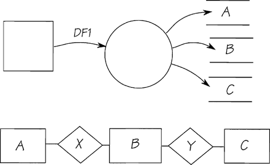
Figure 2.11.25: Sample event-response process model (above) and its corresponding data model (below).
When it stores the data, the process must create the relationships x and Y. Why don’t we show the relationships in the event-response process model? A suggested model appears in Figure 2.11.26.

This model is more comprehensive when it shows the relationships. However, if the relationships X and Y do not contain data, the flows to them are not real data flows (they contain no data), so we prefer to leave them out of our event-response process models and to use the mini specification to specify the creation of the relationships and the accesses to essential data. If a relationship contains data that are stored by the event-response, you should indicate the data flow and the relationship in your model.
The example in Figure 2.11.27 follows the rule that the only flows shown in the model are those containing data. In this case, entity B does not provide data for the process, nor do the two relationships. Because there is no data involved, you can omit the entities, flows, and relationships.
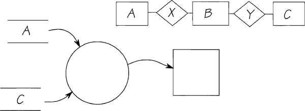
Figure 2.11.27: Data are retrieved from entities A and C. Entity B and its two relationships are used only to locate the correct instances of A and C. Therefore, it’s not shown in the process model.
Sometimes, a process needs too many stores to fit comfortably in the model, as shown in Figure 2.11.28. The solution is shown on the right.

Figure 2.11.28: The many data stores are grouped into one store, which is named and its contents defined in the data dictionary.
Making Event-Responses Unique
Each unique data flow entering the system has a unique response. For example, the system responds differently to an incoming data flow called POLICY CANCELLATION than it does to a data flow called AUTO POLICY CANCELLATION.
For example, in Figure 2.11.29, the incoming flow POLICY CANCELLATION is used when the customer wishes to cancel all policies. There is no data in POLICY CANCELLATION to tell the system which policies to cancel. So there must be a process to look at all possible policies to find those held by a particular customer. Compare that event-response to the one shown in Figure 2.11.30. In this case, the system knows from the data content of AUTO POLICY CANCELLATION that the customer wants to cancel a car insurance policy.
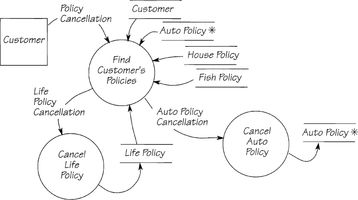
Figure 2.11.29: The response to the event Customer cancels policies. Part of the system’s response is to find all the policies held by the customer.

The content of the arriving data flow tells the system which event has occurred.
The response to each event is unique. That is, the collection of processes and data that make up the response are not exactly duplicated anywhere else in the system. However, a process that is part of one event-response may be duplicated as part of others. Similarly with the entities: The same entities are used by many different event-responses. Because they are part of one event-response does not mean they cannot be part of another.
The best way to deal with duplicate processes is to draw the process wherever it occurs. There is no point in amalgamating all the event-responses that include a duplicate process. If you do this, you lose the control advantages of event partitioning and end up with a large, unmanageable, incomprehensible model. Later, when you write mini specifications, you will avoid duplication by writing one specification and cross-referencing it to all the processes that it defines.
Joining the Event-Responses
Each event-response has a separate event-response process model. For large-scale systems, this may mean building several hundred models. There are advantages to keeping them separate; but for management reasons, you may choose to combine them into a single model and see the whole system, rather than scattered fragments.
To connect the models, join those event-responses that share stored data. An example of a connected model is shown in Figure 2.11.31.
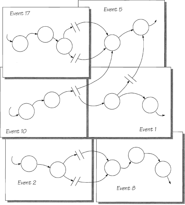
In most systems, you’ll find that the processes that use the same stored data have a strong functional relationship, so the joined event-responses usually fall into coherent groups. Using these groupings, you can reduce the number of bubbles in the model by leveling upward. This leveling effort must seek to minimize the interfaces. In fact, the processes shown at the top level should have no data flowing between them. They should communicate only through the stored data.
Instead of building a leveled model, you can choose to use the CRUD check to manage the inter-event interfaces. You will see more of this approach in Chapter 1.15 CRUD Check.
Summary
The event-response is the most convenient partitioning theme for the essential model. Event-response models are built by linking all of the processes that make up the system’s reaction to an event.
There are two types of events: External events happen outside the system, and temporal events happen when the system must do something at a specific time.
Every data flow in the context diagram is associated with one of the events in the event list. Each input data flow in the context diagram indicates an external event. An external event can also be associated with anything from zero to many output data flows. Output data flows that are not associated with external events are in response to temporal events.
The essential event-response model ignores any processing that is there because of the current (or future) implementation, and shows only the essential processing.
An event-response processes essential stored data and, in some cases, data derived from the essential stores. Each event-response has its own event-response data model. Alternatively, if you prefer to model the event-response processes without an event-response data model, you need to use a system data model.
All of the essential attributes should be CRUD checked (to assure they’re created and referenced, and possibly updated or deleted). This checks that all the events have been discovered and that all the data are relevant.
Event-response models can be built using the current physical model, or directly from the context diagram and user interviews. These models can be leveled upward to make a convenient system-level overview.
What to Do
Trail Guide
![]() Easiest: Once you are comfortable with event-response models, return to the Piccadilly Project. Your first destination is Chapter 1.8 Identifying Events, where you will build the event list. In the chapters that follow, you will model and subsequently refine one of those events.
Easiest: Once you are comfortable with event-response models, return to the Piccadilly Project. Your first destination is Chapter 1.8 Identifying Events, where you will build the event list. In the chapters that follow, you will model and subsequently refine one of those events.
![]() More Difficult and
More Difficult and ![]() Most Difficult: This chapter was not part of your trail, and your Piccadilly Project work resumes in Chapter 1.8 Identifying Events.
Most Difficult: This chapter was not part of your trail, and your Piccadilly Project work resumes in Chapter 1.8 Identifying Events.
![]() Promenade: On this trail, you avoid the hard work. While the others are off to build event-response models for Piccadilly, you’ll go to Chapter 2.12 Mini Specifications, where you’ll read about developing a specification for each bubble in the event-response model.
Promenade: On this trail, you avoid the hard work. While the others are off to build event-response models for Piccadilly, you’ll go to Chapter 2.12 Mini Specifications, where you’ll read about developing a specification for each bubble in the event-response model.