
4.8 The Board Decoupling Problem
A printed circuit board design usually includes a group of decoupling capacitors. These capacitors are connected across the power supply leads near active devices that drive transmission lines. They are usually parallel connected to ground/power planes using vias. It is often assumed that the planar capacitance supplies the first energy when there is a step demand. Because of the typical via geometry, this assumption may not be true.
Designers often consider each decoupling capacitor used on a circuit board as having a series inductance. In this analysis, all transmission line effects are ignored. Capacitors are staggered in value so that the natural frequencies associated with these series resonant circuits are spread out over the spectrum of interest.
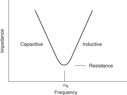
In a circuit sense, capacitors are characterized by their natural frequencies. At this frequency, a capacitor resonates with its series self-inductance or ESL. At this resonant frequency, a capacitor looks like a resistance, which is called the ESR. Above this frequency, a capacitor looks like an inductor. The impedance of a capacitor including these parasitic is shown in Figure 4.4.
Figure 4.4 The impedance of a capacitor near its resonant frequency.
The resonant frequency of a capacitor depends on its construction style and capacitance. In general, a larger capacitor value implies a lower natural frequency. When different capacitor values are paralleled, the resulting impedance is that of paralleled series resonant circuits with different natural frequencies. Consider the frequency where capacitor 1 has an inductive reactance equal to the capacitive reactance of capacitor 2. At this frequency the parallel circuit looks like a parallel resonance, and the impedance rises. When different capacitors are parallel connected, the result is a complex impedance that rises and falls with frequency depending on how the resonances are distributed. When selected capacitors are paralleled, it is possible to limit the impedance to a maximum value over a range of frequencies. A design of this type can be handled on a circuit analyzer. The number of capacitors of any one value and style will vary with the smaller capacitors dominating the count.
A group of parallel decoupling capacitors can be used to supply energy to the active elements of a printed circuit board. For clock rates below 100 MHz this approach can be useful. Above 100 MHz, when transmission line delays are considered, the voltage source is no longer a set of parallel tank circuits. The performance relates to where the capacitors are located. For some devices, it has become necessary to locate a low inductance capacitor array (LICA) directly under the component in question. In this way, the connecting transmission lines are kept short. It should be remembered that there is conducted and radiated emissions out to 1 GHz even when the clock rates are 50 MHz.