
5.8 The Decoupling Capacitor
In Chapter 3, it was pointed out that a decoupling capacitor and its connection can be considered as short sections of transmission lines. The connections that are made inside and outside of the IC are also transmission lines. There are usually several parallel connections to logic traces in an IC driver, as shown in Figure 5.2.
Figure 5.2 A set of connections at a logic structure and a decoupling capacitor.
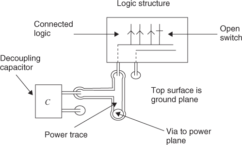
When the logic switch closes, the process of obtaining energy involves transmissions and reflections along all the connected transmission lines. It is important to note that the initial energy will come from the electric field associated with the die and connected logic and power traces. The next nearest source of energy is the ground/power plane capacitance and finally energy will come from the decoupling capacitor. If the energy in this geometry is adequate and if there is sufficient time to gather energy through multiple reflections, a logic signal of sufficient amplitude will propagate over the connected transmission lines and arrive at the logic gates within the time permitted by the error envelope. If the energy used in this transmission is not immediately replaced then the transmission at the next clock time will have a lower voltage.
The path that fields must take to supply energy to the decoupling capacitor is worth discussion. The energy stored in the ground/power plane field cannot cross through a conducting plane. The field carrying this energy must cross through holes and gaps in the ground plane. In Figure 5.2, the field must fold around the gap between the embedded trace and the ground plane. The field on the top of the board is poorly contained. This could be considered an inductance or a section of high impedance transmission line. When a wave finally reaches the capacitor, the reflected wave carrying energy must follow the same path in reverse order. Many round trips are needed to supply the needed energy. In a circuit sense, the field above the ground plane represents inductance. In a transmission line sense, the transmission path has a segment of high characteristic impedance.
Decoupling capacitors have natural frequencies that are usually well below 1 GHz. A 1000-pF capacitor with a series inductance of 0.1 nH has a natural frequency of 159 MHz. A step function with a 100 ps rise time has a rise-time frequency of 1/πτr or 3.18 GHz. These frequencies are over an order of magnitude apart. In a circuit sense, the capacitor has a series inductance that slows the flow of energy.
The ground/power plane has a power time constant of about 1 ns. During this first nanosecond, the voltage will sag at the point of demand. If a DTL (decoupling transmission line) is used, it will be the first element to supply energy after a logic request. The only delay that remains is the connection from the logic switch to the DTL. If a DTL is a part of the IC package, then even this delay can be eliminated.