3.9 Magnetic Component of Cross Coupling
The magnetic flux generated by the culprit line current crosses the conducting path of the victim line. By Lenz's law, a changing current on the culprit line induces a negative current on the victim line. This current is associated with a negative voltage wave that travels to the right and a positive voltage wave that travels to the left. The associated fields have directions that satisfy the requirements of Poynting's vector.
In Figure 3.7, the culprit line is short and it couples to the middle of the victim line L2. Notice L1 is terminated in its characteristic impedance so the culprit wave is absorbed when the wave reaches the end of the line.
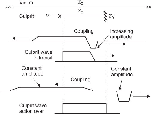
As the culprit wave progresses along L1 the only magnetic flux in transition is along the leading edge. In effect, the coupling is limited to the region where flux (current) is changing on L1. The coupling takes energy from L1 and adds it to L2 on a continuous basis. Each increment of transmission line couples an increment of current to a forward and reverse traveling wave. The coupled forward wave and the culprit wave move to the right at the same velocity, so there can be no coupled energy ahead of the leading edge. The induction process causes a negative pulse of voltage on L2 that increases in amplitude as the culprit wave moves to the right down the line. The pulse width is equal to the rise time of the culprit wave.
A reverse wave moves to the left on L2 as the culprit wave moves to the right. As the leading edge moves to the right, every increment of transmission line couples energy to a victim wave, as it moves to the left. In this mode of coupling the reverse wave reaches a fixed amplitude after the initial rise time. The wave that moves to the left is thus a step function of fixed amplitude. If the culprit wave reaches its termination at time t, the end of the reverse coupled wave will reach the starting point in time 2t. The victim step wave lasts twice as long as the culprit wave. We will see that this reverse coupled wave will be the source of most coupling problems.
The amplitude of the reverse magnetically coupled step wave is given approximately by
where V is the culprit voltage and LM is the mutual inductance per unit length. L is the inductance per unit length used to calculate the characteristic impedance of the victim line. The amplitude of this reverse coupled wave does not depend on rise time or fall time. It only depends on the ratio of inductances. The reverse wave lasts twice as long as the forward wave. The rise time of the reverse wave is double the rise time of the culprit wave. Note that half of the coupled current is supplied to the forward wave. These two factors of two account for the factor of 4 in Equation 3.2.
The forward current pulse caused by inductive coupling is given by
where t is the time of transit and τR is the rise time. The factor of 1/2 results because half the coupled current goes into the reverse wave.
The inductively coupled wave forms are shown in Figure 3.8.
Figure 3.8 Inductive coupling between transmission lines.