
2.7 The Open Circuited Transmission Line
Consider the open circuit transmission line in Figure 2.5a. The diagram is a one-line representation of a two conductor circuit as shown in Figure 2.4. When the switch closes, a step wave (1) of voltage V progresses down the line. When wave (1) reaches the end of the open-ended transmission line, a reflected wave (2) must cancel the current at the end of the line. Poynting's vector for wave (2) requires that only the H field in this wave must reverse in direction. As wave (2) progresses back on the line, the currents sum to zero. The voltage of wave (2) has the same polarity and voltage as the initial wave. Wave (2) simply adds to the voltage placed on the line by wave (1). The result is that the voltage on the line doubles, as wave (2) returns to the voltage source. It is important to note that energy is flowing from the source from the time the switch closes until wave (2) returns to the source.
Figure 2.5 (a) The sequence of individual waves generated on an open line after a switch closure and (b) the wave forms at points A and B.
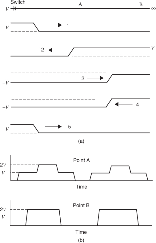
When wave (2) reaches the source, the voltage is incorrect. The reflection of wave (2) is wave (3) that moves forward on the line. It is a negative voltage − V. The sum of waves (1), (2), and (3) is simply V. The current for wave (3) is supplied by wave (2). This means that zero current is supplied by the source voltage. From this point on, the source does not supply any more energy to the line. The total energy supplied to the line is 2V2 t/Z0, where t is the transit time from the source to the open circuit.
When wave (3) reaches the open end of the line, it is again reflected. Since wave (3) is a negative voltage, the reflection must be of the same polarity. The result is that the voltage at the open end of the line is again zero. This assumes no losses on the line.
The voltage at any point on the line is the sum of all the wave voltages that have gone past this point at an earlier time. The voltage at the open end of the line at B is a step wave of double amplitude. The wave form at the midpoint A along the line is a voltage in the sequence 0V, V, 2V, V, 0V, V, … These voltage wave forms are shown in Figure 2.5b.
On an ideal line without losses, this back and forth wave action will continue indefinitely. The energy stored on the entire line is constant except for line losses.
The load on the end of a transmission line may be a logic gate. In many of our discussions, we will treat a logic gate as an open circuit. A gate connection usually looks like a small capacitance, which has the effect of slowing the rise or fall time. A slower rise time reduces both radiation and losses in the dielectric. For a small terminating capacitance, the voltage at the open end of the line will still double, and there can still be radiation along the line. The conductors and the logic switch will dissipate energy as heat as long as there is current flow. There will be radiation along the line where voltage is in transition. In practice, each time the wave makes a round trip; the leading edge will be further attenuated and distorted.
If the terminating capacitance is large then the lumped inductance of the transmission line will resonate with the capacitor resulting in significant ringing. This is circuit behavior.