
4.16 Traces Through Conducting Planes
When a trace crosses through a single conducting plane, the field associated with any signal must cross to the other side of the plane. The only path for the field is the hole (via) used by the trace. This transition will have very little effect on the transmission, as the characteristic impedance of the path will be fairly constant. When a trace crosses more than one conducting layer, the problem is more complex. The problem can best be viewed by locating the path the return current must take. This path will usually be through a nearby via that interconnects the two planes. The result is the field pattern that spreads out between the conducting planes, which means that there is a poorly defined stub associated with the transition of signal between layers. This spreading of fields can result in wave reflections and cross talk. To limit the problem, the vias used for the transition should be close together so that the space used by the fields is limited. Ideally, the path should be coaxial, but this is not practical with simple vias.
A trace that crosses more than one layer might be routed near power on one layer and near ground on another layer. The return path for signal current must cross in the power and ground plane space and through the nearest decoupling capacitor. The transmission line character of this capacitor is in series with the return path. This capacitor supplies field energy for many signals and can be a source of cross coupling. The field pattern in the ground/power plane space spreads out. If this space is shared by several traces in transition, there can be cross talk. An example of a via current path is shown in Figure 4.5.
Figure 4.5 Current path for a signal when a via crosses layers. Note: the characteristic impedance is not controlled in areas C and D. Cross talk can occur in these areas. Area D can have a low characteristic impedance. Wave action takes place between the two current paths.
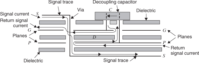
The field is located between the forward and return current arrows just as it would be in any simple transmission line. There are other paths possible, but this is the path that stores the least field energy. This is the path that nature will use.
If the trace transitions between two grounds or two power planes then the field path will not involve a decoupling capacitor. Loops will still form that involves two vias, one for the signal and a second for the ground/power plane interconnection. The fields will still follow a path through holes in the planes. These separated vias will also disrupt the transmission line path used by the logic.