Chapter 10. IrDA
It makes all the difference whether one sees darkness through the light or brightness through the shadows.
—David Lindsay, A Voyage to Arcturus
In the last chapter, we looked at serial communication that takes place over copper wire. Now, we’ll see a serial interface that uses pulses of infrared light to transmit data across short distances, without the need for interconnecting cables. Infrared (IR) transmission of data is becoming commonplace, and IR transceivers are appearing in laptop computers, PDAs, and cell phones. They are also appearing in peripherals such as printers and network interfaces, allowing no-fuss/no-cable connection for people on the move. IR communication is also used by remote controls to talk to their appliances. Your TV, VCR, and DVD remotes all have an IR LED to beam commands across the room.
We’ll start our discussion of IR communication by looking at the most common standard, IrDA. Later, we’ll see just how trivial infrared hardware is to implement.
Introduction to IrDA
IrDA is the infrared transmission standard commonly used in computers and peripherals. IrDA, which stands for “Infrared Data Association,” is a consortium of over 150 companies that maintain and develop the standard. IrDA owes it origins to the infrared communication links used in Hewlett-Packard calculators, known as HP-SIR (Hewlett-Packard Serial Infra Red). The IrDA standard has expanded on HP-SIR significantly and provides a range of protocols that application software may use in communication.
The basic purpose of IrDA is to provide device-to-device communication over short distances. Mobile devices, such as laptops, present a problem when they must be connected to other machines or networks. Chances are the correct cable is not at hand, or one of the machines is not configured correctly to allow networking to take place. When the users are nontechnical types, this can be a real problem. IrDA was developed as the solution to this problem. With IrDA, no cables are required, and standard protocols ensure that devices can exchange information seamlessly. Full details of the IrDA standard and protocols are available from http://www.irda.org.
The expectation is that the IrDA user will be a mobile professional using a laptop or PDA to communicate with other computers, PDAs, or peripherals nearby. This concept has a number of important consequences. The devices communicating will be physically close, so relatively low power transmissions are all that is required. This is important because there are regulations guarding the maximum level of IR radiation that can be emitted. Also, it is reasonable to assume that the two devices that are to communicate will be physically pointed toward each other prior to use. (You don’t change your TV channel by aiming the remote at the cat, unless of course your cat is especially reflective.) It can also be assumed that only two devices will be communicating and that their proximity will exclude interference from other IrDA devices. Thus, IrDA does not have to deal with transmission collision and detection issues that standards such as 802.11 (wireless Ethernet) do. Two IrDA devices may be communicating at one end of a desk, while another two devices are communicating at the other, with no problems at all. Further, a transmission will be initiated by the user, which simplifies the software protocols. An overall guiding principle is that IrDA should be cheap to implement, since it must find its way into low-cost consumer devices.
With all that in mind, IrDA is a point-to-point protocol that uses asynchronous serial transmission over short distances. The initial IrDA specification (1.0) supported data rates of between 2,400 bps and 115.2 kbps over distances of one meter, although some IrDA transceivers can achieve greater distances than this. Initial IR communication takes place at 9,600 bps, and devices negotiate the data rate up or down, depending on their capabilities and needs. Unlike RS-232C, the user does not need to set, know about, or even care what bit rate is being used in communication.
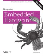
An IrDA transmitter will beam out its transmission at an angle of 15 degrees to 30 degrees on either side of the line of sight. The receiver has a “viewing angle” of 15 degrees on either side of its line of sight (Figure 10-1). So, if two IrDA devices are placed a meter or less apart and generally aimed in each other’s direction, communication will not be a problem. Since its original specification, the standard has been expanded to support higher data rates of 1.152 Mbps and 4 Mbps.
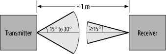
The IrDA standard specifies a number of protocol layers for communication. The IrPHY ( IR Physical Layer ) specification details the hardware layer, including requirements for modulating the outputs of UARTs prior to transmission. The control protocol is known as High-level Data Link Control, or HDLC. IrLAP ( Infrared Link Access Protocol ) uses a HDLC for controlling access to the communication medium. One IrLAP exists per device. An IrLAP connection is essentially a master-slave configuration, or, as they are known in IrDA parlance, primary and secondary devices. The primary device starts communication, sends commands, and handles data-flow control (handshaking). It is rare for a primary device to be anything other than a computer. Secondaries (such as printers) simply respond to requests from primaries. Two primary devices can communicate by one primary assuming the role of a secondary device. Typically, the device that initiates the transfer remains the primary, while the other device becomes a secondary for the duration of the transaction.
IrLMP ( Infrared Link Management Protocol ) provides the device’s software with a means of sharing the single IrLAP between multiple tasks that wish to communicate using IrDA. IrLMP also provides a query protocol by which one device may interrogate another to determine what services are available on the remote system. This query protocol is known as LM-IAS, or Link Management Information Access Service. These are the basic IrDA protocols that all devices must support. Beyond these, IrDA also provides a number of optional services. IrCOMM provides emulation of standard serial-port and parallel-port devices. For application software, the IR port can then be used as if it were just another serial or parallel port. Using IrCOMM, a laptop or PDA can communicate with an IR-enabled printer just as though that printer were physically plugged into the mobile computer. IrLAN allows access to local area networks via the IR interface. IrOBEX provides a mechanism for object exchange between devices, in software that supports object-oriented programming. Finally, Tiny TP is a lightweight protocol allowing applications to perform flow-control (handshaking) when transferring data from one device to another. Figure 10-2 shows how these protocol layers fit together.
At the lower data rates, all protocol handling, packet forming, and error checking is done in software by the processor within an IrDA-compliant device. At higher data rates, dedicated hardware performs these functions, since low-cost embedded processors may not have the computing horsepower to complete these tasks in the time available.
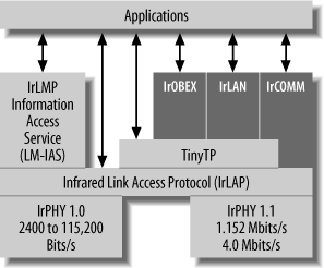
Since IrDA communicates using light, there must be some way to distinguish between a logic 0 and a logic 1 during transmission. To solve this problem, IrDA uses a bit-encoding scheme known as Return-to-Zero, or RZ. With RZ, a frame consists of a transmission interval that is divided into subintervals representing individual bits. A logic zero is represented by a pulse that is 3/16 the width of a bit subinterval, while a logic 1 is represented by the absence of a pulse (Figure 10-3).
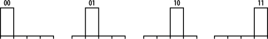
At data rates of 4 Mbps, PPM, or Pulse Position Modulation, is used to distinguish different bits. With PPM, the position of the pulse is varied. Its location within the subinterval determines the transmitted bit pattern. The PPM used in IrDA is known as 4PPM and uses one of four positions to provide the transmission of two data bits (Figure 10-4). In PPM terminology, these are known as cells.
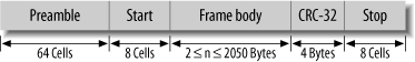
A sample data packet (for a 4 Mbps transmission) is shown in Figure 10-5. It consists of a 64-cell (128-bit) preamble packet, a start packet, the frame body containing the data to be transmitted, a 32-bit Cyclic Redundancy Check (CRC) code, and a packet stop marker. The data frame can be as little as 2 bytes or as large as 2050 bytes.
Now, most UARTs are not capable of performing transmissions in RZ or PPM encoding. Therefore, a special device, known as an EnDec (Encoder Decoder), converts the standard UART output to RZ, and vice versa. A good EnDec to choose is the HSDL-7001 from Agilent or the MCP2120 from Microchip. Some UARTs, such as the MAX3100, incorporate an EnDec on chip and thus may be used to directly interface to an IR transceiver.
An IrDA Interface
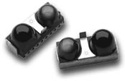
For IR transmission and reception, you can use an individual IR LED and an IR photodiode detector. Alternatively, you can use combined IR transceivers that incorporate both the IR LED and photodiode, along with support components, in a convenient package (Figure 10-6). Several manufacturers make such devices, including Agilent (http://www.agilent.com) and Vishay (http://www.vishay.com). As part of the transceiver packaging, the receiver photodiode is covered by a dark filter to remove visible light and improve IR reception.
The MAX3100 is a general-purpose UART that you can use to add RS-232C or RS-485 interfaces to your embedded computer. It interfaces to a host processor through SPI and can operate on a supply voltage of between 2.7 V and 5.5 V. However, it is also IrDA-compliant and can be configured to output RZ-encoded transmissions and receive RZ-encoded bit streams. All you need to do to make an IrDA interface is add an IR transceiver, some inverter gates, and a few support components. The schematic for the circuit is shown in Figure 10-7.
On the left of the schematic are standard SPI connections to a microcontroller. The MAX3100 also has an interrupt output by which it can notify the host processor of a change in state (such as that it has received data). This interrupt line is pulled high by a 10 kΩ resistor. The MAX3100 also has a shutdown input to place the device in low-power mode. This can be driven by an I/O line of the microcontroller. The MAX3100 also requires a crystal to generate the transmission and reception clocks. This can either be a 1.8432 MHz crystal or a 3.6864 MHz crystal. Either frequency can be used to generate any of the required baud rates through software control of the internal clock dividers. The lower-speed crystal will cause the MAX3100 to use less power.
There are a number of IR transceivers available, and in this schematic I have chosen to use the Agilent HSDL-1001. To interface the MAX3100 to the HSDL-1001, we
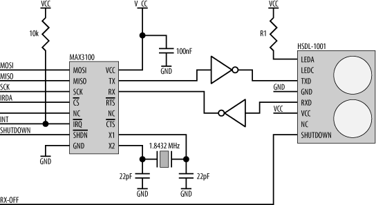
simply need to invert both the transmit (TX) and receive (RX) signals. The HSDL-1001 has a shutdown input that is used to put the receiving photodiode in low-power mode. It has no effect on the transmitting LED, however. This shutdown input may also be driven by an I/O line from the processor. For maximum versatility, this shutdown is controlled independently from the MAX3100’s shutdown. The transmitter LED of the HSDL-1001 requires a current-limiting resistor, R1. This internal LED circuit is essentially the same as the LED circuit we first saw in Chapter 4. When the LED is turned on, the LED’s cathode voltage is a minimum of 2.1 V. The maximum LED current is 240 mA; therefore, from Ohm’s Law, the value for the resistor R1 (when operating from a 5 V supply) is approximately 15 Ω.
One final thing to consider is that IrDA is very susceptible to interference and noise; therefore, all power supplies should be properly decoupled using capacitors for every power pin. Ground planes should also be used to shield the transceiver and associated signal tracks.
Other Infrared Devices
Your TV, VCR, DVD player, air conditioner, and a host of other devices all have infrared ports for receiving commands from their remote controls. The bad news is that none (or at least very few) are IrDA-compliant. Appliance manufacturers tend to do their own thing, and often at their own weird baud rates too. So the previous circuit, which is IrDA-compliant, may or may not work with a particular appliance. However, something as simple as the circuit in Figure 10-8 may do the trick for you.
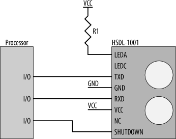
The transmitter of the HSDL-1001 may be driven directly by a processor I/O line. Similarly, the receiver may be sampled using an I/O (as an input) too. So, under software control (and by “manually” toggling the transmitter I/O line as appropriate), the HSDL-1001 may be fed the correct RZ bit stream at the appropriate bit rate. This manual technique is commonly used in standard serial interfaces to implement a serial port on processors that don’t have a UART (and that can’t be expanded). This software UART technique can just as easily be extended to an infrared interface. It’s up to you as the programmer to ensure that you get the timing correct.
Tip
You can’t see the IR output of a remote control with the naked eye, but if you point a camcorder at it, you can. Point the remote into the camera lens and hit a button or two. If you look in the viewfinder while doing this, you can clearly see the control beaming its bits. The way this works is that the CCD imager inside the camera is sensitive to IR as well as visible light. That’s one of the reasons why camcorders are able to shoot so well in low-light levels. To further increase their ability to image at night, some camcorders have IR lights on the front to illuminate the darkness, yet be invisible to people looking on.
Try the trick with the remote. You’ll be surprised at just how bright the IR LEDs really are.
For information on appliance (and remote control) IR protocols and programming, go to http://www.remotecentral.com.