Chapter 7
Conventional Numerical Control
7.1 Introduction
Many of the achievements in computer-aided design and manufacturing have a common origin in numerical control (abbreviated NC). The conceptual framework established during the development of numerical control is still undergoing further refinement and enhancement in today’s CAD/CAM technology. It is appropriate that we devote a major part of this book to the subject of NC.
This chapter defines the basic concepts and applications of conventional numerical control. Modern NC systems rely heavily on computer technology. Chapter 8 deals with the topic of NC part programming, a procedure that depends greatly on computer-aided methods. Chapter 9 is concerned with computer control in NC systems.
Numerical control defined
Numerical control can be defined as a form of programmable automation in which the process is controlled by numbers, letters, and symbols. In NC, the numbers form a program of instructions designed for a particular workpart or job. When the job changes, the program of instructions is changed. This capability to change the program for each new job is what gives NC its flexibility. It is much easier to write new programs than to make major changes in the production equipment.
NC technology has been applied to a wide variety of operations, including drafting, assembly, inspection, sheet metal pressworking, and spot welding. However, numerical control finds its principal applications in metal machining processes. The machined workparts are designed in various sizes and shapes, and most machined parts produced in industry today are made in small to medium-size batches. To produce each part, a sequence of drilling operations may be required, or a series of turning or milling operations. The suitability of NC for these kinds of jobs is the reason for the tremendous growth of numerical control in the metal-working industry over the last 25 years.
Historical background
Conventional NC is based largely on the pioneering work of a man named John T. Parsons. In the late 1940s, Parsons conceived a method of using punched cards containing coordinate position data to control a machine tool. The machine was directed to move in small increments, thus generating the desired surface of an airfoil. In 1948, Parsons demonstrated his concept to the U.S. Air Force, which subsequently sponsored a series of research projects at the Servomechanisms Laboratory of the Massachusetts Institute of Technology.
The initial work at MIT involved the development of a prototype NC milling machine, by retrofitting a conventional tracer mill with position Servomechanisms for the three machine tool axes. The first demonstration of the NC prototype was held in 1952. By 1953, the potential usefulness of the NC concept had been proven.
Shortly thereafter, the machine tool builders began initiating their own development projects to introduce commercial NC units. Also, certain user industries, especially airframe builders, worked to devise numerical control machines to satisfy their own particular needs. The Air Force continued its encouragement of NC development by sponsoring additional research at MIT to design a part programming language that could be used for controlling the NC machines. This work resulted in the APT language, which stands for Automatically Programmed Tools. The objective of the APT research was to provide a means by which the part programmer could communicate the machining instructions to the machine tool in simple English-like statements. Although the APT language has been criticized as being too large for many computers, it nevertheless represents a major accomplishment. APT is still widely used in industry today, and most other modern part programming languages are based on APT concepts.
7.2 Basic Components of an NC System
An operational numerical control system consists of the following three basic components:
1. Program of instructions
2. Controller unit, also called a machine control unit (MCU)
3. Machine tool or other controlled process
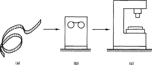
The general relationship among the three components is illustrated in Figure 7.1. The program of instructions serves as the input to the controller unit, which in turn commands the machine tool or other process to be controlled. We will discuss the three components in the sections below.
Program of instructions
The program of instructions is the detailed step-by-step set of directions which tell the machine tool what to do. It is coded in numerical or symbolic form on some type of input medium that can be interpreted by the controller unit. The most common input medium today is 1-in-wide punched tape. Over the years, other forms of input media have been used, including punched cards, magnetic tape, and even 35-mm motion picture film.
There are two other methods of input to the NC system which should be mentioned. The first is by manual entry of instructional data to the controller unit. This method is called manual data input, abbreviated MDI, and is appropriate only for relatively simple jobs where the order will not be repeated. We will discuss MDI more thoroughly in Chapter 8. The second other method of input is by means
Figure 7.1 Three basic components of a numerical control system: (a) program of instruction; (b) controller unit; (c) machine tool.
of a direct link with a computer. This is called direct numerical control, or DNC, and we discuss this in Chapter 9.
The program of instructions is prepared by someone called a part programmer. The programmer’s job is to provide a set of detailed instructions by which the sequence of processing steps is to be performed. For a machining operation, the processing steps involve the relative movement between the cutting tool and the workpiece.
Controller unit
The second basic component of the NC system is the controller unit. This consists of the electronics and hardware that read and interpret the program of instructions and convert it into mechanical actions of the machine tool. The typical elements of a conventional NC controller unit include the tape reader, a data buffer, signal output channels to the machine tool, feedback channels from the machine tool, and the sequence controls to coordinate the overall operation of the foregoing elements. It should be noted that nearly all modern NC systems today are sold with a microcomputer as the controller unit. This type of NC is called computer numerical control (CNC). We discuss CNC in Chapter 9.
The tape reader is an electromechanical device for winding and reading the punched tape containing the program of instructions. The data contained on the tape are read into the data buffer. The purpose of this device is to store the input instructions in logical blocks of information. A block of information usually represents one complete step in the sequence of processing elements. For example, one block may be the data required to move the machine table to a certain position and drill a hole at that location.
The signal output channels are connected to the servomotors and other controls in the machine tool. Through these channels, the instructions are sent to the machine tool from the controller unit. To make certain that the instructions have been properly executed by the machine, feedback data are sent back to the controller via the feedback channels. The most important function of this return loop is to assure that the table and workpart have been properly located with respect to the tool.
Sequence controls coordinate the activities of the other elements of the controller unit. The tape reader is actuated to read data into the buffer from the tape, signals are sent to and from the machine tool, and so on. These types of operations must be synchronized and this is the function of the sequence controls.
Another element of the NC system, which may be physically part of the controller unit or part of the machine tool, is the control panel. The control panel or control console contains the dials and switches by which the machine operator runs the NC system. It may also contain data displays to provide information to the operator. Although the NC system is an automatic system, the human operator is still needed to turn the machine on and off, to change tools (some NC systems have automatic tool changers), to load and unload the machine, and to perform various other duties. To be able to discharge these duties, the operator must be able to control the system, and this is done through the control panel.
Machine tool or other controlled process
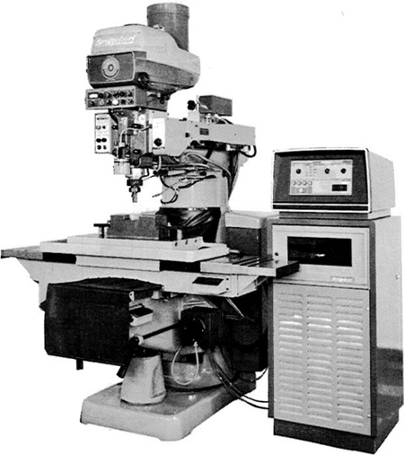
The third basic component of an NC system is the machine tool or other controlled process. It is the part of the NC system which performs useful work. In the most common example of an NC system, one designed to perform machining operations, the machine tool consists of the worktable and spindle as well as the motors and controls necessary to drive them. It also includes the cutting tools, work fixtures, and other auxiliary equipment needed in the machining operation. Figure 7.2 illustrates an NC machine tool.
Figure 7.2 NC system showing machine tool and controller. (Courtesy of Bridgeport Machines Division of Textron Inc.)
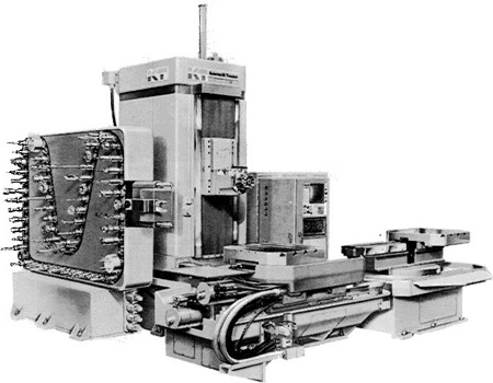
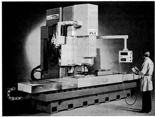
NC machines range in complexity from simple tape-controlled drill presses to highly sophisticated and versatile machining centers. The NC machining center was first introduced in the late 1950s. It is a multifunction machine which incorporates several timesaving features into a single piece of automated production equipment. First, a machining center is capable of performing a variety of different operations: drilling, tapping, reaming, milling, and boring. Second, it has the capacity to change tools automatically under tape command. A variety of machining operations means that a variety of cutting tools are required. The tools are kept in a tool drum or other holding device. When the tape calls a particular tool, the drum rotates to position the tool for insertion into the spindle. The automatic tool changer then grasps the tool and places it into the spindle chuck. A third capability of the NC machining center is workpiece positioning. The machine table can orient the job so that it can be machined on several surfaces, as required. Finally, a fourth feature possessed by some machining centers is the presence of two tables or pallets on which the workpiece can be fixtured. While the machining sequence is being performed on one workpart, the operator can be unloading the previously completed piece, and loading the next one. This improves machine tool utilization because the machine does not have to stand idle during loading and unloading of the workparts. An example of an NC machining center is shown in Figure 7.3.
Figure 7.3 NC machining center with computer control. (Courtesy of Kearney ' Trecker Corp.)
7.3 The NC Procedure
To utilize numerical control in manufacturing, the following steps must be accomplished.
1.Process planning. The engineering drawing of the workpart must be interpreted in terms of the manufacturing processes to be used. This step is referred to as process planning and it is concerned with the preparation of a route sheet. The route sheet is a listing of the sequence of operations which must be performed on the workpart. It is called a route sheet because it also lists the machines through which the part must be routed in order to accomplish the sequence of operations. We assume that some of the operations will be performed on one or more NC machines.
2.Part programming. A part programmer plans the process for the portions of the job to be accomplished by NC. Part programmers are knowledgeable about the machining process and they have been trained to program for numerical control. They are responsible for planning the sequence of machining steps to be performed by NC and to document these in a special format. There are two ways to program for NC:
Manual part programming
Computer-assisted part programming
In manual part programming, the machining instructions are prepared on a form called a part program manuscript. The manuscript is a listing of the relative cutter/workpiece positions which must be followed to machine the part. In computer-assisted part programming, much of the tedious computational work required in manual part programming is transferred to the computer. This is especially appropriate for complex workpiece geometries and jobs with many machining steps. Use of the computer in these situations results in significant savings in part programming time.
3.Tape preparation. A punched tape is prepared from the part programmer’s NC process plan. In manual part programming, the punched tape is prepared directly from the part program manuscript on a typewriterlike device equipped with tape punching capability. In computer-assisted part programming, the computer interprets the list of part programming instructions, performs the necessary calculations to convert this into a detailed set of machine tool motion commands, and then controls a tape punch device to prepare the tape for the specific NC machine.
4.Tape verification. After the punched tape has been prepared, a method is usually provided for checking the accuracy of the tape. Sometimes the tape is checked by running it through a computer program which plots the various tool movements (or table movements) on paper. In this way, major errors in the tape can be discovered. The “acid test” of the tape involves trying it out on the machine tool to make the part. A foam or plastic material is sometimes used for this tryout. Programming errors are not uncommon, and it may require about three attempts before the tape is correct and ready to use.
5.Production. The final step in the NC procedure is to use the NC tape in production. This involves ordering the raw workparts, specifying and preparing the tooling and any special fixturing that may be required, and setting up the NC machine tool for the job. The machine tool operator’s function during production is to load the raw workpart in the machine and establish the starting position of the cutting tool relative to the workpiece. The NC system then takes over and machines the part according to the instructions on tape. When the part is completed, the operator removes it from the machine and loads the next part.
7.4 NC Coordinate Systems
In order for the part programmer to plan the sequence of positions and movements of the cutting tool relative to the workpiece, it is necessary to establish a standard axis system by which the relative positions can be specified. Using an NC drill press as an example, the drill spindle is in a fixed vertical position, and the table is moved and controlled relative to the spindle. However, to make things easier for the programmer, we adopt the viewpoint that the workpiece is stationary while the drill bit is moved relative to it. Accordingly, the coordinate system of axes is established with respect to the machine table.
Two axes, x and y, are defined in the plane of the table, as shown in Figure 7.4. The z axis is perpendicular to this plane and movement in the z direction is controlled by the vertical motion of the spindle. The positive and negative directions of motion of tool relative to table along these axes are as shown in Figure 7.4. NC drill presses are classified as either two-axis or three-axis machines, depending on whether or not they have the capability to control the z axis.
A numerical control milling machine and similar machine tools (boring mill, for example) use an axis system similar to that of the drill press. However, in addition to the three linear axes, these machines may possess the capacity to control
Figure 7.4 NC ma-Machine table chine tool axis system for milling and drilling operations.
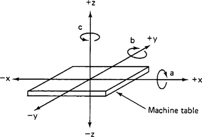
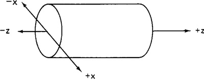
Figure 7.5 NC machine tool axis system for turning operation.
one or more rotational axes. Three rotational axes are defined in NC: the a, b, and c axes. These axes specify angles about the x, y, and z axes, respectively. To distinguish positive from negative angular motions, the “right-hand rule” can be used. Using the right hand with the thumb pointing in the positive linear axis direction (x, y, or z), the fingers of the hand are curled to point in the positive rotational direction.
For turning operations, two axes are normally all that are required to command the movement of the tool relative to the rotating workpiece. The z axis is the axis of rotation of the workpart, and x axis defines the radial location of the cutting tool. This arrangement is illustrated in Figure 7.5.
The purpose of the coordinate system is to provide a means of locating the tool in relation to the workpiece. Depending on the NC machine, the part programmer may have several different options available for specifying this location.
Fixed zero and floating zero
The programmer must determine the position of the tool relative to the origin (zero point) of the coordinate system. NC machines have either of two methods for specifying the zero point. The first possibility is for the machine to have a fixed zero. In this case, the origin is always located at the same position on the machine table. Usually, that position is the southwest corner (lower left-hand corner) of the table and all tool locations will be defined by positive x and y coordinates.
The second and more common feature on modern NC machines allows the machine operator to set the zero point at any position on the machine table. This feature is called floating zero. The part programmer is the one who decides where the zero point should be located. The decision is based on part programming convenience. For example, the workpart may be symmetrical and the zero point should be established at the center of symmetry. The location of the zero point is communicated to the machine operator. At the beginning of the job, the operator moves the tool under manual control to some “target point” on the table. The target point is some convenient place on the workpiece or table for the operator to position the tool. For example, it might be a predrilled hole in the workpiece. The target point has been referenced to the zero point by the part programmer. In fact, the programmer may have selected the target point as the zero point for tool positioning. When the tool has been positioned at the target point, the machine operator
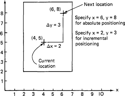
Figure 7.6 Absolute versus incremental positioning.
presses a “zero” button on the machine tool console, which tells the machine where the origin is located for subsequent tool movements.
Absolute positioning and incremental positioning
Another option sometimes available to the part programmer is to use either an absolute system of tool positioning or an incremental system. Absolute positioning means that the tool locations are always defined in relation to the zero point. If a hole is to be drilled at a spot that is 8 in. above the x axis and 6 in. to the right of the y axis, the coordinate location of the hole would be specified as x = +6.000 and y = +8.000. By contrast, incremental positioning means that the next tool location must be defined with reference to the previous tool location. If in our drilling example, suppose that the previous hole had been drilled at an absolute postion of x = +4.000 and y = +5.000. Accordingly, the incremental position instructions would be specified as x = +2.000 and y = +3.000 in order to move the drill to the desired spot. Figure 7.6 illustrates the difference between absolute and incremental positioning.
7.5 NC Motion Control Systems
In order to accomplish the machining process, the cutting tool and workpiece must be moved relative to each other. In NC, there are three basic types of motion control systems:
1. Point-to-point
2. Straight cut
3. Contouring
Point-to-point systems represent the lowest level of motion control between the tool and workpiece. Contouring represents the highest level of control.
Point-to-point NC
Point-to-point (PTP) is also sometimes called a positioning system. In PTP, the objective of the machine tool control system is to move the cutting tool to a predefined location. The speed or path by which this movement is accomplished is not important in point-to-point NC. Once the tool reaches the desired location, the machining operation is performed at that position.
NC drill presses are a good example of PTP systems. The spindle must first be positioned at a particular location on the workpiece. This is done under PTP control. Then the drilling of the hole is performed at the location, and so forth. Since no cutting is performed between holes, there is no need for controlling the relative motion of the tool and workpiece between hole locations. Figure 7.7 illustrates the point-to-point type of control.
Positioning systems are the simplest machine tool control systems and are therefore the least expensive of the three types. However, for certain processes, such as drilling operations and spot welding, PTP is perfectly suited to the task and any higher level of control would be unnecessary.
Straight-cut NC
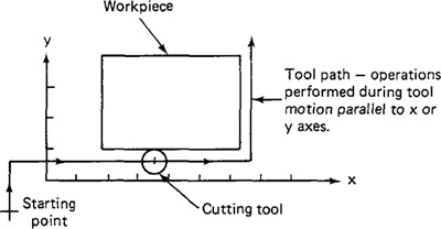
Straight-cut control systems are capable of moving the cutting tool parallel to one of the major axes at a controlled rate suitable for machining. It is therefore appropriate for performing milling operations to fabricate workpieces of rectangular configurations. With this type of NC system it is not possible to combine movements in more than a single axis direction. Therefore, angular cuts on the workpiece would not be possible. An example of a-straight-cut operation is shown in Figure 7.8. An NC machine capable of straight cut movements is also capable of PTP movements.
Figure 7.7 Point-to-point (positioning) NC system.
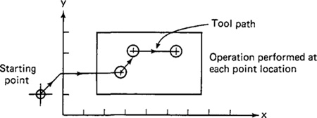
Figure 7.8 Straight-cut system.
Contouring NC
Contouring is the most complex, the most flexible, and the most expensive type of machine tool control. It is capable of performing both PTP and straight-cut operations. In addition, the distinguishing feature of contouring NC systems is their capacity for simultaneous control of more than one axis movement of the machine tool. The path of the cutter is continuously controlled to generate the desired geometry of the workpiece. For this reason, contouring systems are also called continuous-path NC systems. Straight or plane surfaces at any orientation, circular paths, conical shapes, or most any other mathematically definable form are possible under contouring control. Figure 7.9 illustrates the versatility of continuous-path NC. Milling and turning operations are common examples of the use of contouring control.
In order to machine a curved path in a numerical control contouring system, the direction of the feed rate must continuously be changed so as to follow the path. This is accomplished by breaking the curved path into very short straight-line segments that approximate the curve. Then the tool is commanded to machine each segment in succession. What results is a machined outline that closely approaches
Figure 7.9 Contouring (continuous path) NC system for two-dimensional operations. (Reprinted from Olesten [9].)
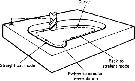
Figure 7.10 Approximation of a curved path in NC by a series of straight-line segments. The accuracy of the approximation is controlled by the “tolerance” between the actual curve and the maximum deviation of the straight-line segments. In (a), the tolerance is defined on the inside of the curve. It is also possible to define the tolerance on the outside of the curve, as in (b). Finally, the tolerance can be specified on both inside and outside, as shown in (c).
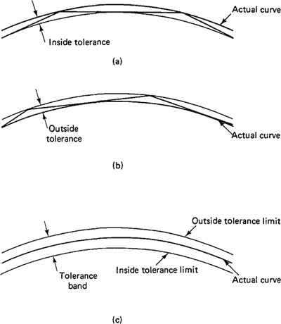
the desired shape. The maximum error between the two can be controlled by the length of the individual line segments, as illustrated in Figure 7.10.
7.6 Applications of Numerical Control
Numerical control systems are widely used in industry today, especially in the metalworking industry. By far the most common application of NC is for metal cutting machine tools. Within this category, numerically controlled equipment has been built to perform virtually the entire range of material removal processes, including:
Milling
Drilling and related processes
Boring
Grinding
Sawing
Within the machining category, NC machine tools are appropriate for certain jobs and inappropriate for others. Following are the general characteristics of production jobs in metal machining for which numerical control would be most appropriate:
1. Parts are processed frequently and in small lot sizes.
2. The part geometry is complex.
3. Many operations must be performed on the part in its processing.
4. Much metal needs to be removed.
5. Engineering design changes are likely.
6. Close tolerances must be held on the workpart.
7. It is an expensive part where mistakes in processing would be costly.
8. The parts require 100% inspection.
It has been estimated that most manufactured parts are produced in lot sizes of 50 or fewer. Small-lot and batch production jobs represent the ideal situations for the application of NC. This is made possible by the capability to program the NC machine and to save that program for subsequent use in future orders. If the NC programs are long and complicated (complex part geometry, many operations, much metal removed), this makes NC all the more appropriate when compared to manual methods of production. If engineering design changes or shifts in the production schedule are likely, the use of tape control provides the flexibility needed to adapt to these changes. Finally, if quality and inspection are important issues (close tolerances, high part cost, 100% inspection required), NC would be most suitable, owing to its high accuracy and repeatability.
In order to justify that a job be processed by numerical control methods, it is not necessary that the job possess every one of these attributes. However, the more of these characteristics that are present, the more likely it is that the part is a good candidate for NC.
Figures 7.11 and 7.12 illustrate several NC machine tools that perform machining operations.
In addition to metal machining, numerical control has been applied to a variety of other operations. The following, although not a complete list, will give the reader an idea of the wide range of potential applications of NC:
Pressworking machine tools
Welding machines
Inspection machines
Figure 7.11 Four-axis NC chucking center for turning operations. (Courtesy of Cincinnati Milacron.)
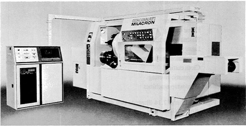
Figure 7.12 NC milling machine. (Courtesy of Kearney ' Trecker Corp.)
Assembly machines
Tube bending
Flame cutting
Plasma arc cutting
Laser beam processes
Automated knitting machines
Cloth cutting
Automatic riveting
Wire-wrap machines
Figures 7.13 and 7.14 illustrate two of the NC machines that perform these non-machining applications.
7.7 Economics of Numerical Control
The great variety of numerical control applications were explored in the preceding section. We also examined the general characteristics of production jobs for which NC seems to be particularly well suited. When properly applied, numerical control provides the user with a significant number of economic advantages. In this section we present the advantages and disadvantages of NC compared to conventional manual methods of production.
Advantages of NC
Following are the advantages of numerical control when it is utilized in the types of production jobs described in Section 7.6:
1. Reduced nonproductive time. Numerical control has little or no effect on the basic metal cutting (or other manufacturing) process. However, NC can increase the proportion of time the machine is engaged in the actual process. It accomplishes this by means of fewer setups, less time in setting up, reduced work-piece handling time, automatic tool changes on some machines, and so on.
In a University of Michigan survey reported by Smith and Evans [10], a comparison was made between the machining cycle times for conventional machine tools versus the cycle times for NC machines. NC cycle times, as a percentage of their conventional counterparts, ranged from 35% for five-axis machining centers to 65% for presswork punching [10, p. 185]. The advantage for numerical control tends to increase with the more complex processes.
2. Reduced fixturing. NC requires fixtures which are simpler and less costly to fabricate because the positioning is done by the NC tape rather than the jig or fixture.
Figure 7.13 NC plasma arc cutting machine (Courtesy of Heath Corp.)
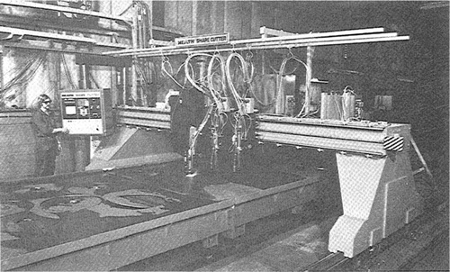
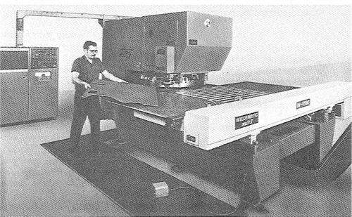
Figure 7.14 NC punch press for sheet metal operations. (Courtesy of Warner ' Swasey Company, Wiedemann Division.)
3. Reduced manufacturing lead time. Because jobs can be set up more quickly with NC and fewer setups are generally required with NC, the lead time to deliver a job to the customer is reduced. According to the University of Michigan survey [10, p. 241], average lead-time reductions range between 26 and 44%, depending on type of machine tool.
4. Greater manufacturing flexibility. With numerical control it is less difficult to adapt to engineering design changes, alterations of the production schedule, changeovers in jobs for rush orders, and so on.
5. Improved quality control. NC is ideal for complicated workparts where the chances of human mistakes are high. Numerical control produces parts with greater accuracy, reduced scrap, and lower inspection requirements. Smith and Evans report that the average scrap decrease from NC ranges from 31 to 44% [10, p. 212], depending on type of machine tool, and that the annual cost savings from reduced inspection needs of NC are about 38% [10, p. 214].
6. Reduced inventory. Owing to fewer setups and shorter lead times with numerical control, the amount of inventory carried by the company is reduced.
7. Reduced floor space requirements. Since one NC machining center can often accomplish the production of several conventional machines, the amount of floor space required in an NC shop is usually less than in a conventional shop.
Disadvantages of NC
Along with the advantages of NC, there are several features about NC which must be considered disadvantages:
1. Higher investment cost. Numerical control machine tools represent a more sophisticated and complex technology. This technology costs more to buy than its non-NC counterpart. The higher cost requires manufacturing managements to use these machines more aggressively than ordinary equipment. High machine utilization is essential in order to get reasonable returns on investment. Machine shops must operate their NC machines two or three shifts per day to achieve this high machine utilization.
2. Higher maintenance cost. Because NC is a more complex technology and because NC machines are used harder, the maintenance problem becomes more acute. Although the reliability of NC systems has been improved over the years, maintenance costs for NC machines will generally be higher than for conventional machine tools. According to the companies responding to the University of Michigan survey, the average percentage increase in NC maintenance cost compared to non-NC ranged from 48% for milling machines to 63% for machining centers [10, p. 206].
3. Finding and/or training NC personnel. Certain aspects of numerical control shop operations require a higher skill level than conventional operations. Part programmers and NC maintenance personnel are two skill areas where available personnel are in short supply. The problems of finding, hiring, and training these people must be considered a disadvantage to the NC shop.
7.8 Summary
In this chapter we have attempted to cover the fundamentals of numerical control technology and how NC is used in manufacturing. Numerical control continues to be a developing technology. Each year, NC machines with new features and refinements are offered to industrial customers who are eager to improve productivity. The common theme in the majority of these innovations involves the expanding use of the computer. This trend began in the late 1950s with the development of the APT language. It gained momentum in the late 1960s, when NC machines were first controlled directly by computers. Further innovations have been made in both the programming and control of NC machines during the 1970s and early 1980s as computer technology has advanced to provide us with smaller, less expensive, yet more powerful computers. In the following two chapters, we examine some of these developments in numerical control. Chapter 8 is concerned with NC part programming. We will discuss the basics of manual part programming, but most of the chapter focuses on computer-assisted part programming, with particular emphasis on the APT language. Since the introduction of APT, many innovations have been made in NC languages and NC programming. Among these are the use of interactive graphics and voice communication for part programming.
Chapter 9 deals with the control of NC machines and how computers are used to perform this control function. We trace the development of NC controls up to the current-day computerized NC systems. Included within this chapter is a discussion of direct numerical control (DNC) and adaptive control. We conclude Chapter 9 by exploring some of the new developments and trends in NC technology.
References
[1] BEERCHECK, R. C., “Machine Tools: Cutting Edge of Technology,” Machine Design, January 25, 1979, pp. 18–47.
[2] CHEDS, J. J., Numerical Control Part Programming, Industrial Press, Inc., New York, 1973.
[3] DALLAS, D. B. (Ed.), Tool and Manufacturing Engineers Handbook, 3rd ed., Society of Manufacturing Engineers/McGraw-Hill Book Company, New York, 1976, Chapter 12.
[4] DEVRIES, M. F., “Two Case Studies of the Investment Justification for N/C Machinery Using the MAPI Method,” in Education Module, Manufacturing Productivity Educational Committee, Purdue Research Foundation, West Lafayette, Ind., 1977.
[5] DROY, J., “Machining Centers Mean Production Profits,” Production Engineering, June, 1981, pp. 50–54.
[6] GROOVER, M. P., Automation, Production Systems, and Computer-Aided Manufacturing, Prentice-Hall, Inc., Englewood Cliffs, N.J., 1980.
[7] HEGLAND, D. E., “Numerical Control—Your Best Investment in Productivity,” Production Engineering, March, 1981, pp. 42–47.
[8] JENKINS, L. J., GAY, J. M., MULDOON, T. F., SMITH, D., HUNT, R. C., and HARRINGTON, J., JR., “Getting More Out of NC.” American Machinist, October, 1981, pp. 185–192.
[9] OLESTEN, N. O., Numerical Control, John Wiley ' Sons, Inc. (Wiley-Interscience), New York, 1970.
[10] SMITH, D. N., and EVANS, L., Management Standards for Computer and Numerical Controls, University of Michigan, Ann Arbor, 1977.