4.3 Analysis of Form in Architecture
With this background, let’s begin the analysis of the form of a real engineering system, the centrifugal pump of Figure 4.5. Box 4.3 contains an explanation of the principles of operation of this pump. This example was chosen as the reference case because it is “modular”; the parts are not absolutely discrete like the members of a team, nor are they integral like the parts of the heart. In addition, the pump has only nine parts. It is a “simple system,” judging on the basis of the guideline presented in Section 3.3 that we find atomic parts at Level 1.

Figure 4.5 Expanded view of the centrifugal pump.
(Source: PumpBiz.com)
We acknowledge that the pump is a simple, almost trivial example, and that applying the techniques of system architecture to such a simple system is like taking a sledge hammer to a thumb tack. However, we can learn a lot from a simple system before tackling a truly complex one.
Defining the System
We will use the questions in Table 4.1 to organize our discussion of form. The first question asks us to identify the system and its form: “What is the system?”
The procedure to answer Question 4a is to examine the system and create an abstraction of form that conveys the important information and implies a boundary of the system that is consistent with the detailed boundary that will be drawn in answering Question 4e. Abstractions were discussed in Section 2.4.
For Question 4a in this case, we create the abstraction of form “pump,” which not only brings to the surface the idea of something that moves fluid but also hides all details of motors, impeller, and the like. We implicitly draw the system boundary around the parts listed in Figure 4.5, which separates the system from the context. Outside the system, we presumably have the hoses that connect to the pump input or output, the mechanical support for the pump, and the controller and power supply for the motor. The outcome of this task is simply an object that represents the abstraction for the entire system, the object labeled “Pump” in Figure 4.6.
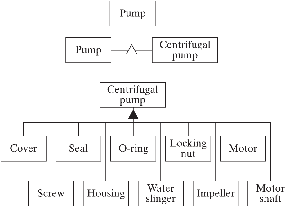
Figure 4.6 Specialization and decomposition of a centrifugal pump in OPM.
We could have chosen “centrifugal pump” as a more specific abstraction than “pump” for our system. Other types of pumps include axial flow pumps and positive displacement pumps. Figure 4.6 shows the objects called pump and centrifugal pump connected by the OPM symbol for the specialization relationship (an unfilled triangle). Specialization was introduced in Section 3.4 and is used extensively in design.
Identifying the Entities of Form
Continuing to Question 4b of Table 4.1, we now seek to identify the entities in the form domain called elements of form. The procedure to answer Question 4b is explained below by example. In brief, we will start with a reference parts list as the initial set of abstractions, decompose some elements further if necessary, combine or eliminate elements where possible, and use hierarchy to identify the most important elements of form.
The “parts list” for the pump is indicated by the numbered parts in Figure 4.5 and is a useful place to start creating abstractions. For this simple pump system, we will use the parts list as the set of abstractions defining elements of form, with a few exceptions. The first is the motor, which actually has a non-rotating element and a rotating motor shaft. Some elements connect to the motor and some connect to the shaft, and this difference is important. Calling all of this “the motor” would hide too much information. Anticipating the internal function of the elements of form, one can guess that the shaft also is involved with different functions than the motor. Therefore, we create two elements to describe the motor and the motor shaft, producing the full list of entities in Figure 4.6. To illustrate that this decomposition can be shown as a graph or as a list, we have included a list-like representation in Table 4.2. In general, information about a system can be contained in a graph or list, and we will use the two interchangeably.
Table 4.2 | Parts list and elements of form for a centrifugal pump
| Parts List | Abstractions Used to Designate Elements of Form |
|---|---|
| Cover | Cover |
| Screws | Screws (class of 5) |
| O-ring | O-ring |
| Locking nut | Locking nut |
| Impeller | Impeller |
| Seal | Seal |
| Housing | Housing |
| Water slinger | Water slinger |
| Motor | Motor |
| Motor shaft |
A careful examination of Figure 4.5 reveals that there are five screws. Yet in the decomposition of Figure 4.6, we identified only one abstraction, called “screw.” Implicitly, we created a class called “Screw” and then identified five instances of the class. The class/instance relationship was discussed in Section 3.4, and the OPM symbol was introduced in Table 3.2.
It is not uncommon, in decomposing systems, to find entities that simply can be combined for convenience, because they are integrally part of delivering a single function. For example, in the pump list of elements in Table 4.2, we could have combined the locking nut with the impeller, since the only function of the locking nut is to secure the impeller to the shaft.
The Pump as a Medium-Complexity System
If we briefly think of the pump as a medium-complexity system (in which we find atomic parts at Level 2), we can apply hierarchic reasoning, following the approach of Section 3.3. Remember that hierarchy is defined as a system in which grades are ranked one above the other because they have more scope, importance, performance, responsibility, or function.
Table 4.3 | Hierarchy in the elements of form of the centrifugal pump
| Centrifugal Pump |
| Cover, Impeller, Housing, Motor shaft, Motor |
| O-ring, Seal, Water slinger |
| Screws (class), Locking nut |
Hierarchy can be applied to built systems. A simple table showing hierarchy for the pump is shown in Table 4.3. We identify five key parts: The cover and housing contain the fluid and provide interfaces; the impeller does the work on the fluid; the motor drives the shaft and supports the housing; and the motor shaft drives the impeller. We can also identify the fasteners as the least important elements, leaving the remaining three parts in the middle rank. This table gives us a quite different impression than the graphical decomposition of Figure 4.6 and the list in Table 4.2. Based on the information in Table 4.3, we might first try to reason about the five highest-grade objects, to understand them thoroughly before including the lower-priority elements.
Figure 4.7 shows an OPM representation of a hierarchic decomposition that extends two levels down. There is no formal structure (other than decomposition) and no functional interaction implied by the diagram!
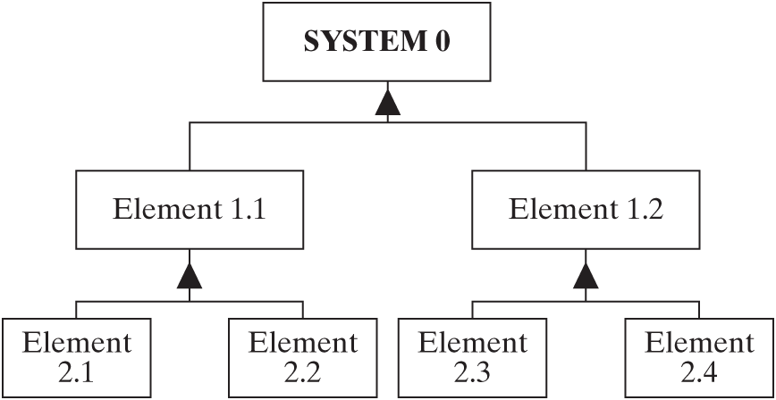
Figure 4.7 OPM representations of multilevel decomposition.
Even though the pump has only ten entities of form, it is possible to convert its representation from a one-level decomposition (Figure 4.6) to a two-level decomposition, as shown in Figure 4.8.

Figure 4.8 Two-level decompositional view of a centrifugal pump in OPM.
The elements at Level 1 in Figure 4.8 are now not real parts but simply abstractions. In this case, the abstractions “pump assembly” and “motor assembly” were selected. These could have been chosen because the motor is highly integral and the other elements highly interconnected. Or perhaps it was because the pump assembly has a distinct function (increase the pressure of water) and the motor has another distinct function (drive the pump).
The creation of Level 1 abstractions is not unique, as discussed in Section 3.3. For example, the Level 1 abstractions could have been “rotating components” (which would include the lock nut, impeller, water slinger, and motor shaft) and “non-rotating components” (the rest of the elements).
To summarize the approaches used to identify the entities of form of a medium-complexity system, consider the OPM diagram shown in Figure 4.9.

Figure 4.9 Summary of relationships used to manage complexity in OPM.
Starting at the top left, the more general idea of pump specializes (Section 3.4) to the more specific idea of centrifugal pump. Centrifugal pump decomposes through two levels of hierarchy (Section 3.3). At the first level, we have created the intermediate abstractions called pump assembly and motor assembly. These then decompose to ten elements of form. One of these is in fact not a single object, but a class called “Screw,” of which there are actually several instances (Section 3.4). One of the other objects, the motor shaft, exhibits the attribute of state called spinning, which can have the states of yes (the shaft is turning) and no (it is not turning).
In summary:
Analyzing form requires creating an abstraction of form that conveys the important information, but not too much information, and implies a boundary of the system.
The elements of form can be represented as a hierarchic decomposition—a set of objects that represent the first- and potentially second-level abstractions of the decomposed system, which can be represented in either a graphical or a list format.