6.3 Non-idealities, Supporting Layers, and Interfaces in System Architecture
Non-idealities in System Architecture
Looking at Figure 6.8, we observe that the seal, O-ring, motor, motor shaft, screws, locking nuts, power supply, and mounting are not yet associated with an internal process. What do these other instrument objects do?
The answer is that up to this point, we have analyzed only the idealized value delivery aspects of the pump, and there is a lot more to making a successful system. Getting the value delivery pathway right is necessary, but not sufficient. Other aspects of system function are necessary as well. These include non-idealities in the value pathway, supporting functions, and interface functions.
Non-idealities are the subject of Question 6b of Table 6.1. There is a whole class of these non-idealities that are associated with managing the operands: moving them, containing them, or storing them while the value processes are taking place. In the circulatory system, there are check valves to ensure that there is no reverse flow of blood. In a team, documents must be stored and controlled by a document system. At the physical level of computation, there are lots of bits stored and moved.
Another, related class of internal functions provides extra performance or robustness. For example, we might improve the performance of John in Team X (Figure 6.5e) by adding electronic design tools and rendering. We might improve the reliability of bread baking by monitoring the moisture content of the dough (Figure 6.5). And sometimes we need to offset biases, such as for the operational amplifier of Chapter 2.
If we are reverse-engineering, we can examine the instruments that are not associated with the principal and secondary value flows, and reason how these either help manage the operands or improve performance or robustness.
Applying this procedure to the pump of Figure 6.8, we identify the seal and O-ring as unassigned instruments of form that are “close” to the value pathway; they touch the water. The O-ring helps to contain the water, while the seal reduces leakage of the water by the shaft. The cover and housing already support ideal internal functions, but they have an additional non-ideal function: They guide and contain the water as it moves through the impeller. These non-idealities are shown in Figure 6.8.
It is interesting to note that bubblesort in Figure 6.9 does not appear to have any non-idealities. Digital information systems are supposed to be deterministic and not to have to deal with uncertainties. However, the run time implementation of this code would have additional instructions for moving and storing data that can be considered management of the operands. In communications systems, non-idealities include checking on correct transmission with processes such as error detection and correction codes.
Supporting Functions and Layers in Architecture
The objects of form on the value delivery pathway (such as the impeller and cover) themselves have to be supported. In general, physical objects have to be supported against gravity or other applied loads, powered and controlled. In organizations such as Team X, support comes from human resources, information technology, and management. Question 6c asks us to examine these supporting functions and their instruments.
A classic case of supporting layers is found in networked information systems. Bubblesort may run in an application layer, but if data are sent from bubblesort out on a network, layer upon layer will be supporting the application layer. In both the OSI seven-layer model and the Internet four-layer model, all of the value is created in the application layers. The remaining layers are all supporting. In Chapter 7, we will explore the architecture of networked information systems to illustrate this point.
Figure 6.10 shows the full architecture of the centrifugal pump. In general, the architecture of a system can be modeled in these layers: value operands, value processes, value instruments, and then several alternating layers of supporting processes and instruments. When identifying processes and instruments in the supporting layers, reflect on how the value instruments are supported mechanically, energetically, biochemically, informatically, and so on.
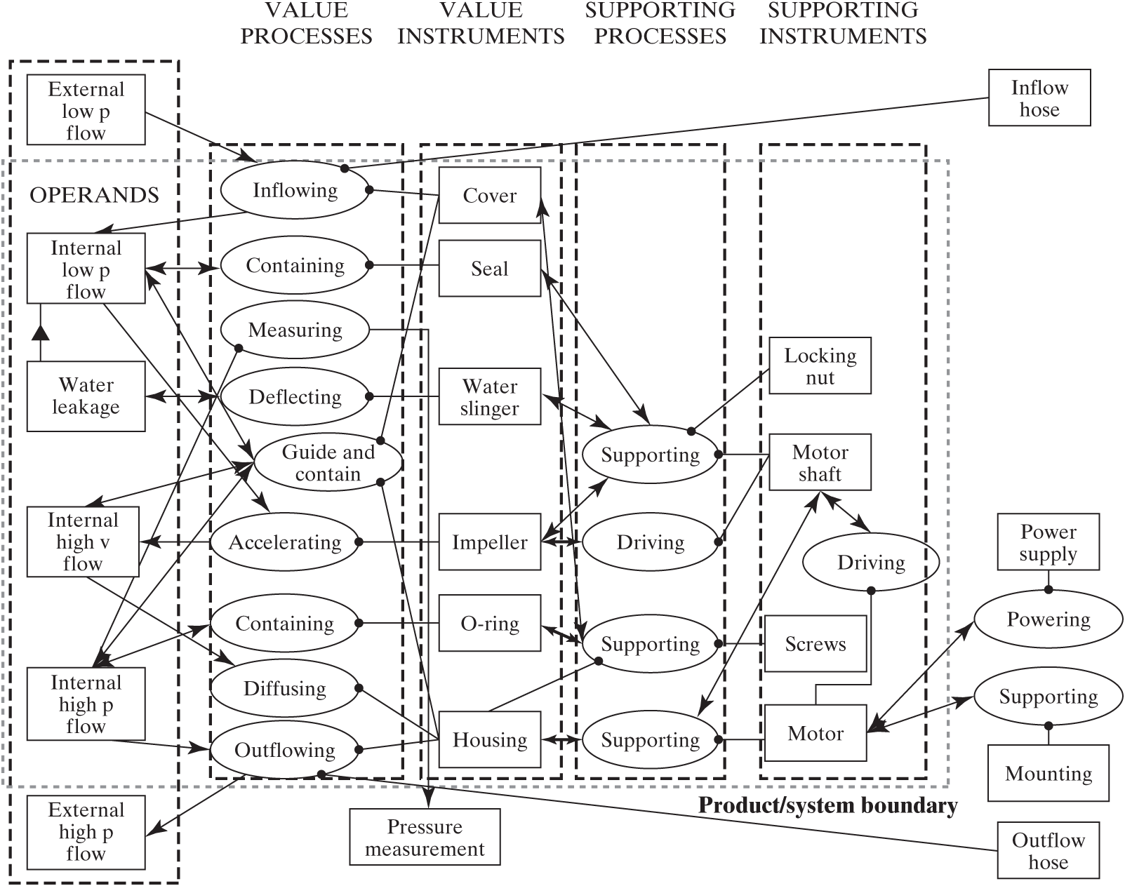
Figure 6.10 Pump system architecture, including supporting and interfacing processes.
The details of Figure 6.10 show some interesting features of supporting processes and form. Note that the motor drives the shaft but also supports the shaft. The shaft in turn drives and supports the impeller. The housing, which is in the value instrument column, also supports the cover and O-ring, which are also in the value instrument column. Thus the assignment of an instrument to one column or another is not unique, but in general, instruments should be identified as close to the value processes as possible.
System Interfaces in Form and Function
Boundaries are central to the definition of a system (Section 2.4). The importance of clearly communicating where the system boundary is located cannot be overstated. The system boundary divides the entities in the product/system from the accompanying system and defines the entities under the control of the architect. It identifies the interfaces that must be controlled. Question 6d of Table 6.1 focuses our attention on boundaries interfaces.
When something is passed into or out of a system, there is a system interface at the boundary crossing. For the pump, Figure 6.10 shows five potential interfaces: inflowing fluid, outflowing fluid, external powering, external supporting, and one to represent the pressure measurement leaving the product/system.
It is the obligation of the architect to specify the interfaces. Whether this is done by citing a standard or writing an interface control document, there is certain information that must be specified, as shown symbolically in Figure 6.11. Like all entities in a system, the interface has form and function (operand and process). These include:
The operand that passes through the boundary, which will be the same on both sides.
The process of passing the operand, which is usually shared or common at the boundary.
The two interface instruments, which have some formal relationship. They can be androgynous, meaning that the interface form is identical on both sides, or they can be compatible, meaning that they are different but they somehow fit together.
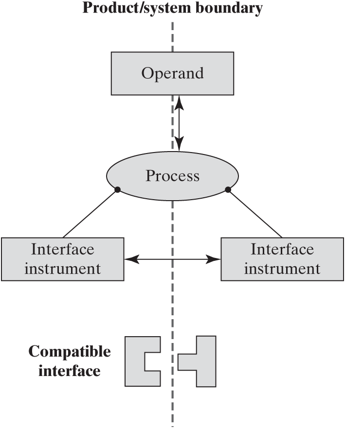
Figure 6.11 Model of an interface as a system boundary.
For the inflowing process the operand is the water, which passes through the boundary unchanged. The instruments are a hose and the cover, which contains some fitting for the hose (outflowing is similar). The powering interface process passes current and involves the power cable of the motor connecting to a socket. The measurement is transmitted from an internal wire to an external one. The mechanical supporting process passes load from the motor legs to a mounting plate.
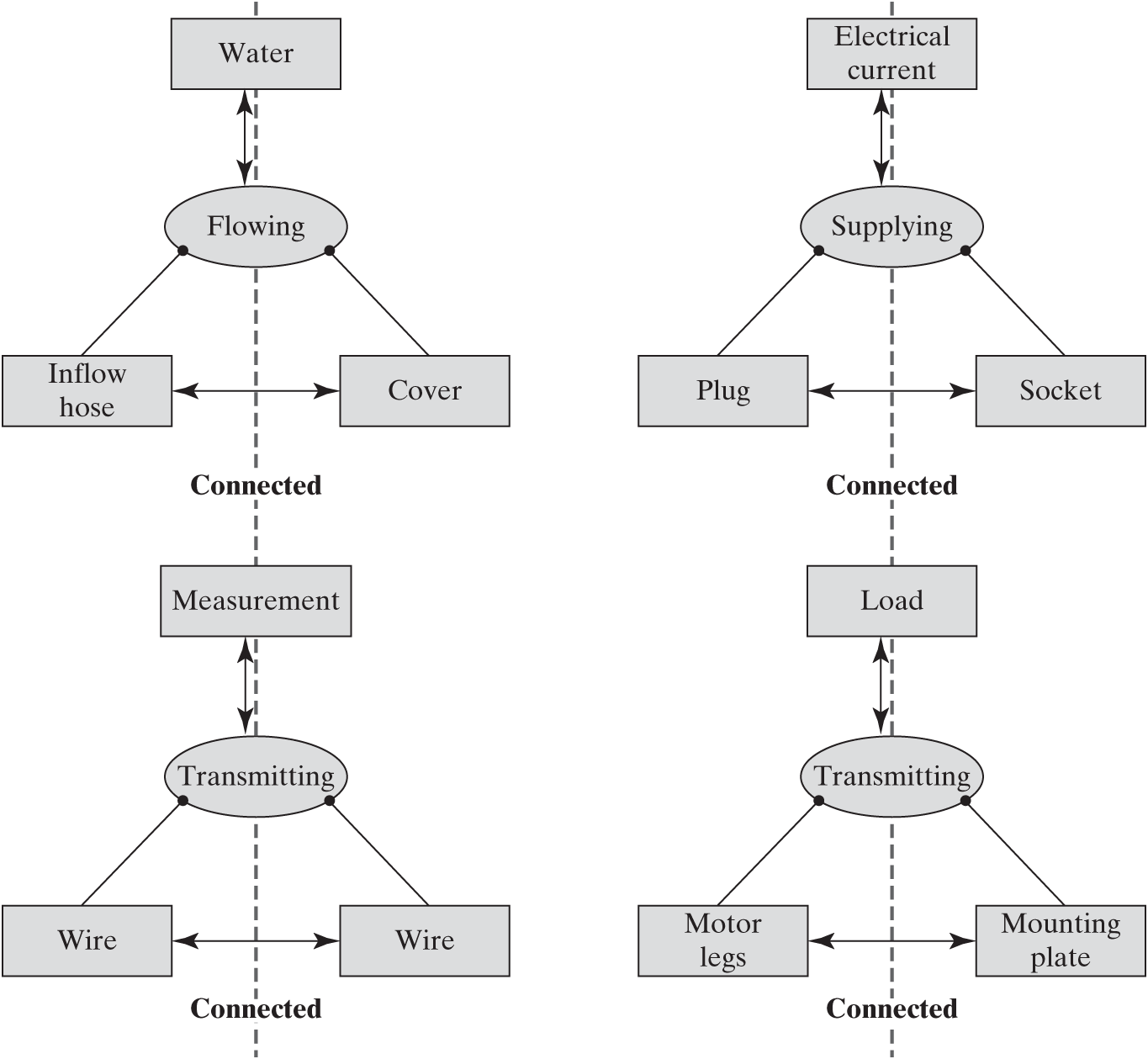
Figure 6.12 Models of an interface as a system boundary.
A similar analysis of interfaces for bubblesort can be done by examining Figure 6.9. At the start of the procedure, two operands are passed by the importing function: the external array and the length. The instruments of the passing are a call statement in the main routine and the procedure statement. The exporting function passes the shared value-related operand back, with the return statement serving as the instrument, although the sorted array may just be left at the global address of the initial array.
In summary:
Even though there is nominally an idealized value delivery pathway along which primary and secondary value are delivered, in reality there are non-idealities that must be accommodated in the architecture of a system. These are often associated with the management of the operands—containing them, moving them, or storing them.
Architecture can be represented in layers of operands, processes, and instruments of form. The supporting processes and the additional instruments often appear in one or two additional layers.
Interfaces have form and function. At a minimum, the definition of an interface should include the common operand, the process, and the compatible instruments associated with the product/system and the accompanying system.