6.2 System Architecture: Form and Function
Mapping of Form and Function
How would we describe the architectural differences between the two bridges shown in Figure 6.2? Both have the same external function (carrying vehicles), and they look surprisingly similar in form (both have two central towers, a roadbed, and cables).
Yet the system architecture of these two bridges is different because their form–function mappings are different. The roadbed (form) of the cable-stay bridge carries load in compression (function), whereas the suspension bridge does not. The anchors (form) for the suspension bridge main cables are reacting to loads from the main cables (function). Since the cable-stay bridge carries tension in the roadbed, it cannot span as long a distance as a suspension bridge.
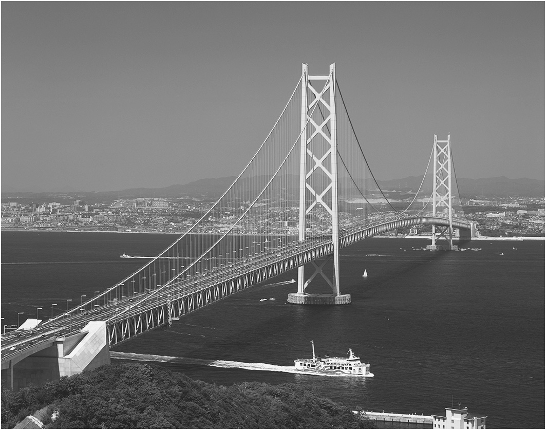
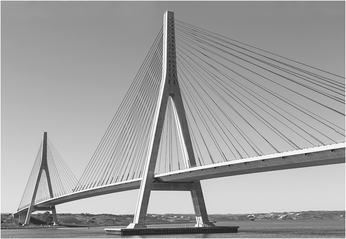
Figure 6.2 A suspension bridge (left) and a cable-stay bridge (right).
(Source: (Left) JTB MEDIA CREATION, Inc./Alamy (Right) CBCK/Shutterstock.)
Question 6a of Table 6.1 is the crux of Part 2 and of this entire text. “How are the instrument objects mapped to the internal process? How does the formal structure support functional interaction? How does it influence emergence?” These questions define the important features of the architecture of a system—the relationship between form and function.
The center diagram of Figure 6.1 represents the simplest, and most commonly assumed architecture of a system: a simple flow-through functional architecture with distinct operands created at each stage. It further assumes that there is only one instrument linked to each internal process, and only one internal process linked to each instrument. This is a system that obeys the independence axiom.
[1] If only life were so simple!
Figure 6.3 illustrates this simple architecture in a system for the production of sliced bread. As shown on the left, there is an instrument that does the mixing (a mixer), another that does the baking (an oven), and a third that does the slicing (a cutter). Each object of form is instrumental in one and only one process. Each process produces a distinct operand, so the function can be easily stated as something like produce + outgoing operand.
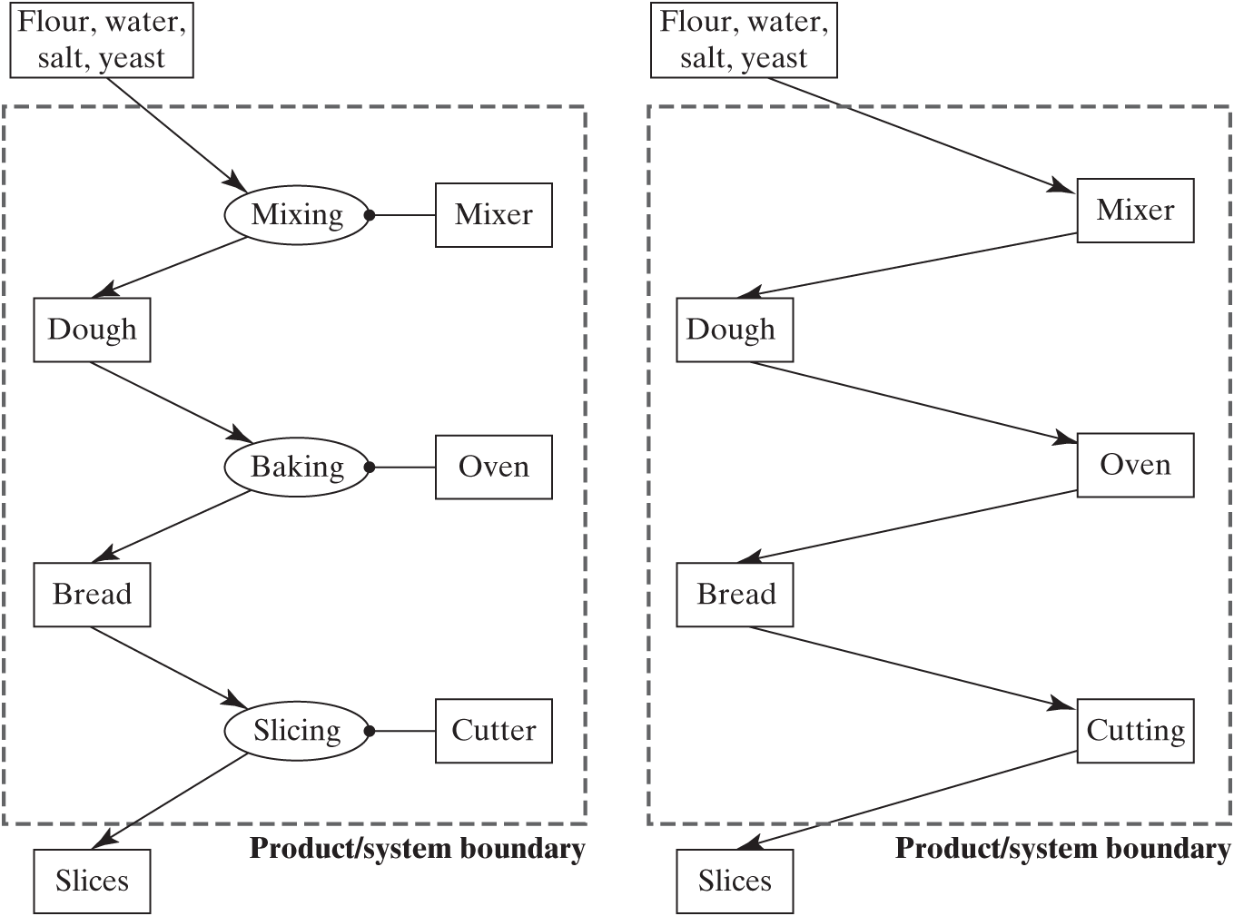
Figure 6.3 Simple system architecture of sliced bread making.
In such systems, the mental leap to the image on the right in Figure 6.3 is quite easy. The form is the proxy for the process it executes. [2] Dough is thought of as going into an oven, and bread emerges. One can temporarily suppress the processes altogether and imagine the operands passing through the instrument objects. When it works, it is quite useful, but is this paradigm generalizable?
One need only look at a slightly more complex representation of the architecture of producing slices of bread (Figure 6.4) to see the problem. The abstraction of a “mixer” has been replaced by a stirrer (such as a spoon), a bowl, and a stir agent (the cook). Likewise, the oven and the cutter have been shown in more detail. We no longer have the one-to-one mapping of elements of form and processes. And there is one instrument mapped to two processes; this becomes clear when we realize that the “stir agent” and the “slice agent” are the same person—the cook—as indicated by the structural link. Now the diagram on the right does not make much sense. What does it mean to go into and out of a bowl or a knife? Using the instrument as the proxy for the process no longer makes sense.
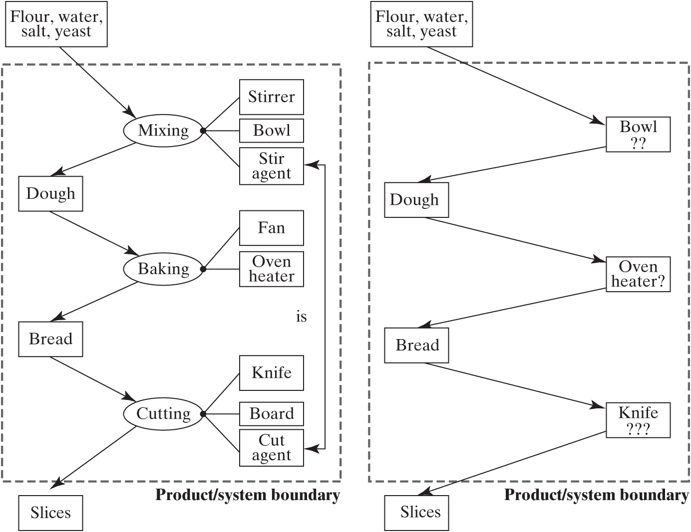
Figure 6.4 A not-so-simple system architecture of sliced bread making.
Clearly, the simple model of one instrument for each process and one process for each instrument is not general. In reality, operands are created and destroyed not by elements of form but by processes. The mapping of form to function cannot be expected to be one-to-one. To gain perspective on various patterns in system architecture, we will examine fragments of architecture for some simple systems.
No instrument, or combined operand and instrument object
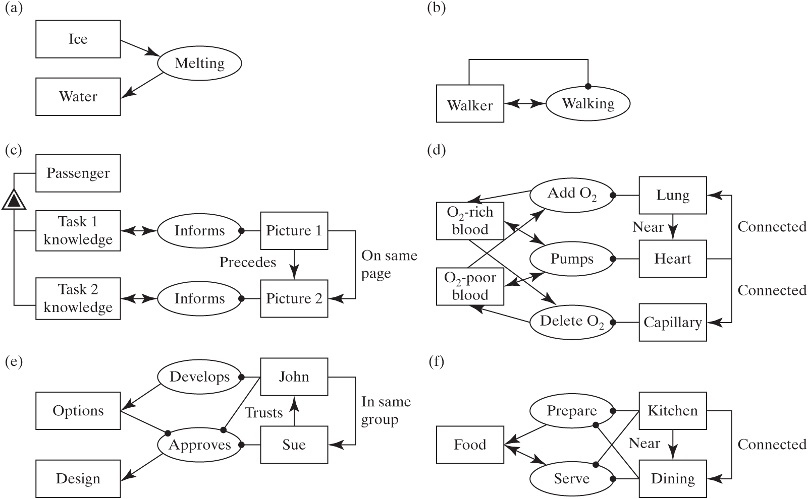
Figure 6.5 Fragments of system architecture of simple systems: (a) no instrument, (b) operand instrument, (c) one-to-one mapping affecting the same operand, (d) one-to-one mapping with multiple operands, (e) one-to-many mapping of form to processes, (f) many-to-many mapping of form to process.
Figure 6.5b shows a case where the operand, a person, is also the instrument of the process, walking. People “walk themselves.” When it appears that there is no instrument for a process, consider that an operand might also be the instrument of the process.
To understand this apparent paradox, we have to look carefully at our definitions. We defined form (Box 4.1) as “the . . . embodiment of a system that exists [an object] . . . and is instrumental in the execution of function. . . . Form exists prior to the execution of function.” The person in Figure 6.5b satisfies this definition; she or he is the instrument of walking and exists prior to walking. We defined an operand (Box 5.2) as “an object . . .And we know that an operand is an object that need not exist prior to the execution of function and is in some way acted upon by the function.” The person in Figure 6.5b also satisfies this definition; he or she is an object that happens to exist prior to the execution of function and is acted upon by the function. Thus, the definitions of form objects and operand objects are not mutually exclusive. An object can be both an element of form and an operand.
One-to-one mapping with increasing operand complexity
In Figure 6.5d the heart, lung, and capillaries that make up the circulatory system all map one-to-one to a process. But on the operand side, the pumping process affects both oxygen-rich and oxygen-poor blood, while the adding and deleting processes create and destroy abstractions of oxygen-rich and oxygen-poor blood. From these three examples, we see that even in systems with one-to-one mapping of instrument to process, complexity can grow on the process-operand side.
One-to-many and many-to-many mapping of process and operand
The bread slicing system of Figure 6.4, if we assume that the stir agent and the cut agent are different people, is the simplest case where one-to-one mapping breaks down. Here there are many instruments for each process, but only one process for each instrument. This is a very common occurrence. Very often, even simple processes need several instruments.
Moving up in complexity, Figure 6.5e depicts a fragment of Team X from Chapter 2. Team member John develops the design options, but he might help choose the design as well. Sue works only on the design decision and approval. John is now an instrument of two processes. This is also an example where an operand (the option) is subsequently used as an instrument. We also encountered this in the discussion of functional architecture in Section 5.5.
Finally, a fragment of the house example of Chapter 4 is shown in Figure 6.5f. Food is prepared primarily in the kitchen of a house, but some “preparation” can occur in the dining room (tossing salad, carving meat). Likewise, serving occurs primarily in the dining room, but some serving can occur in the kitchen (laying food out buffet-style, for instance). For these many-to-many mappings, the architect has to really focus on understanding all of the roles of each of the instruments.
Box 6.3 illustrates how the architecture for sliced bread making is represented in SysML.
To show decomposition of the mixer or of the oven, we could use a SysML structural diagram such as the block definition diagram (BDD) shown in Figure 6.7.
Identifying Form-to-Process Mapping
We are now ready to outline a procedure to address part of Question 6a in Table 6.1: “How are the instrument objects mapped to the internal processes?”
Identify all of the important elements of form (Chapter 4).
Identify all of the value-related internal processes and operands (Chapter 5).
Ask what element of form is needed to execute each process (it may be among the identified elements of form, or it may lead to a new one).
Map the elements of form to the internal processes.
Identify the remaining unassigned elements of form, and try to reason about what process they might map to and whether this process is important to represent at this time.
After this procedure, reflect on the complexity of the form-to-process mapping and emergence.
Now we can apply this procedure to the analysis of the system architecture of the pump (Figure 6.8), which was developed from information in Figures 4.6 and 5.20. We will go process by process and identify the link between the internal processes and instrument objects. On the primary value pathway, the impeller is the instrument of accelerating the flow, and the housing is an instrument of diffusing as well as outflowing. Among the secondary value delivery functions, the water slinger is the instrument of deflecting the flow. There is no instrument of form shown in Figure 6.8 for the measuring function, because none was on the parts list of the motor in Chapter 4. Clearly we missed an instrument, such as a sensor. The mapping of form to process is nearly one-to-one, but the housing carries two processes. To obtain the desired emergence, the design of this part must skillfully blend these two functions. We still have many elements of form unassigned to processes, which we will return to below.
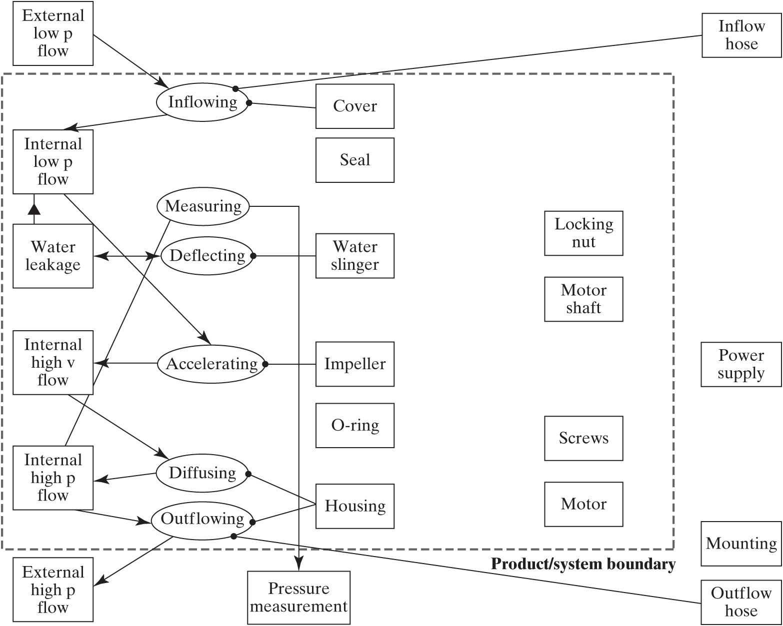
Figure 6.8 Pump system architecture with primary and secondary value-related functions.
The system architecture of the bubblesort routine is shown in Figure 6.9, which was developed from Figures 4.20 and 5.19. The importing, looping, testing, and exporting processes are associated with a single element of form (a line of code), assuming that we count the end . . . statement as part of the for or if statements. The exchanging process is spread over several lines of code.
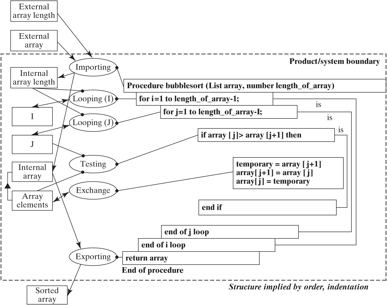
Figure 6.9 Bubblesort system architecture.
The emergence of function form is clear in bubblesort. At its core are the three lines of code that do the exchanging. The “if” statement creates conditional exchanging. Adding the two “for” statements gives sorting, the desired emergent function.
Structure of Form Enables and Informs Functional Interactions
The externally delivered function emerges as form is assembled, and this emergence is enabled and informed by the structure of the form. Recall that structure—the formal relationships among the elements of form—can be of three types (Section 4.4). Connections indicate how the elements of form are linked or interconnected. Location and placement, including spatial/topological relations as well as address and sequence, indicate where elements are located. Intangible relationships that simply exist include membership, ownership, and human relationships.
In general, functional interaction takes place because there is a connection of form. But be forewarned: Some functional interactions can take place in the absence of any connection whatsoever; examples include gravitational and electromagnetic interactions and some types of “ballistic” interactions among particles and fields.
In general, location and intangible relationships do not directly enable interactions and emergence of function but, rather, inform and influence the nature of the interaction or the degree of performance. In software, however, location, sequence, and address can be enabling of function.
We can illustrate this important role of structure by reexamining some of the very simple fragments in Figure 6.5.
In the circulatory system of Figure 6.5d, the connections enable the functional interaction: the movement of blood. The fact that the lung and heart are nearby informs performance but is not essential to function. It is easier to pump large quantities of blood because the heart and lungs are close together.
The passenger safety information card of Figure 6.5c is an information system, where the important feature of structure is sequence. The sequence of pictures is implicitly the sequence of instructions. If the pictures on the instruction card were reversed in order, the instructions would be invalid or at least confusing, so sequence enables emergence. The other spatial/topological relationship—that the individual pictures are on the same page (or, for software, in the same routine)—is a convenience. It may improve the reliability of the system (an “-ility”) or how fast a passenger can execute the instructions (performance), but it is not essential to emergence of function. In Team X (Figure 6.5e) the fact that Sue trusts John (an intangible human relationship) probably improves performance.
Both the OPM and matrix representations have a way of showing which element of form is an instrument of which process, but neither has such an explicit way of showing which formal structural relationship enables which functional interaction. This is left to the architect to reason about and remember.
Identifying How Formal Structure Enables Function and Performance
Question 6a of Table 6.1 includes the questions “How does the formal structure support functional interaction?” and “How does it influence emergence?” We propose the following procedure to answer these questions.
Identify which among the elements of form are likely to be important structural relationships (Chapter 4).
Identify the functional interactions among the related internal processes (Chapter 5).
Ask what formal structure is necessary to enable each of the functional interactions.
Ask what formal structures would inform the other emergent properties of performance and the “ilities.”
Add, remove, or modify the structural relationships as necessary to support important functional interactions.
The spatial/topological structure of form among the lines of code of bubblesort is explicit, represented by sequence and the relationship of what is “within” other lines (informally represented by indentation). In Chapter 4, we summarized which lines share access to variables (this is only static information; the lines share the variables, but we are not sure yet whether they actually pass the variables—the interaction). In Chapter 5, we summarized the functional interactions. How well do the structure and the functional interactions match up?
Clearly, the sharing of variables allows the exchange of variables, so the data flow is relatively simple. The control flow is enabled in part by the static sequence. In this case, sequence is essential to emergence; if any two of the lines of code in the procedure were reversed, sorting would fail to emerge. The dynamic aspects of control flow, the movement of the control token in conditional statements, is a bit unresolved. Our model of system architecture would suggest that there must be some enabling structure that allows the flow of these control tokens. but none is evident in the code. There must therefore be, buried somewhere in the compiled version of the code, a sharing of some “control space” that enables the flow of the control tokens.
The important functional interactions for the pump revealed by Figure 6.8 are that the internal low-pressure flow is passed from the inflowing process, whose instrument is the cover, to the accelerating process, whose instrument is the impeller. A second important interaction is that the internal high-velocity flow is passed from the accelerating process, whose instrument is the impeller, to the diffusing process, whose instrument is the housing.
This suggests that there should be some sort of connectivity formal structure between the cover and the impeller, and again between the impeller and the housing, that enables these important functional interactions. Examining our connectivity structure diagram for the pump (Figure 4.16), we find no such connections. The connections in the pump support the interactions among elements of the mechanical parts, not the fluid flow. If we look at the summary of the structural relationships in Table 4.7, we observe that the only formal structure that exists between the impeller and the cover is a spatial relationship, which is listed as “close to” in Figure 4.14.
Can a spatial relationship of “close to” support interaction in a fluid flow? In fact it can, as was discussed in Section 4.4. Imagine the water stream from a garden hose emerging from the nozzle. If the nozzle were close to and pointed at a bucket, the water would be transferred from the hose to the bucket. In certain cases of such “ballistic” flows, proximity and alignment, which are spatial structural relationships, allow interaction as well. The formal structure of “close to” also informs performance. A smaller gap will allow a higher net rise in pressure.
In summary:
The system architecture consists of instrument objects mapped onto internal processes. The processes interact through the exchange of operands, or through action on common operands. The relationship between the objects of form is the structure of the system (Figure 6.1).
The mapping between the formal instruments and processes can be one-to-one (the simple case), many instruments to one process, or one instrument to many processes. In some cases, an operand that exists prior to the process can act as the instrument.
The structure of the form supports emergence of function. Some aspects of structure actually are instruments of the interactions between the associated processes.
The structure also informs the performance of the system—how well the system executes its functions.