7.3 Concept
The Notion of Concept
The intellectual distance from the solution-neutral function to the architecture of the system is a large gap to jump. In order to help, we create an intellectual construct known as concept. This intellectual construct is not strictly necessary, but it is very useful in reasoning about complex systems.
Concept is the high-level mapping of function to form. It is defined in Box 7.2. Concept is a way to conveniently and concisely convey the vision of the system. To put it another way, the concept
Is the transition point from the solution-neutral to the solution-specific.
Must allow for value-related functions to be executed, enabled by form.
Establishes the vocabulary for the solution and is the beginning of the development of architecture.
Implicitly sets the design parameters of the system.
Implicitly sets the level of technology.
Both concept and architecture contain mappings of function to form. However, concept explains how function is mapped to form in a general way. Figure 7.3 suggests this notional mapping of function and form by concept, and by the much more elaborate information that is contained in the architecture. If you have a concept in mind, it is a guide to building the architecture. If you have an architecture in front of you, concept rationalizes the architecture.
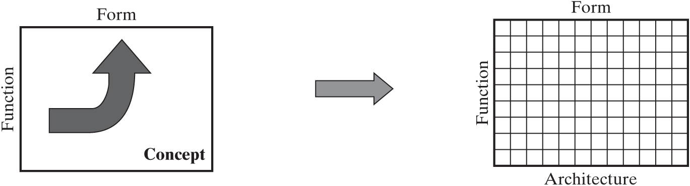
Figure 7.3 Relationship between concept and architecture.
We can use simple systems to illustrate these main points. The solution-neutral function of the pump is “moving fluid.” The concept is water (specific operand) pressurizing (specific process) using a centrifugal pump (specific instrument of form). Here specific means “in the solution-specific domain,” as opposed to the solution-neutral domain. So now we have transitions from the solution-neutral to the solution-specific by choosing the concept. Referring to a centrifugal pump immediately establishes a vocabulary of motor, housing, and impeller; sets design parameters such as impeller speed and pressure rise; and implicitly sets the level of technology (higher than moving water with buckets, but lower than high-temperature turbo machinery). In contrast to one simple phrase describing concept (a centrifugal pump pressurizing water), the definition of the architecture would require a detailed description of the parts, their structure, and their mapping to internal functions, as was developed in Chapter 6.
Likewise, bubblesort is actually the name of a concept. The solution-neutral function is “sorting the array.” The concept is array (specific operand) exchanging sequentially (specific process) using bubblesort (specific instrument of form). Bubblesort allows for the sorting but is not as fast as other algorithms such as quicksort. Mentioning bubblesort to anyone who has studied algorithms immediately conjures up a simple algorithm, a solution vocabulary, and a set of instrument objects that must be specified to define the architecture (the code). From these two examples, it is clear how much more is defined about a system when the concept is chosen than is defined before the concept is chosen—and how much more must be specified to define the architecture.
Framework for Developing Concept
Figure 7.4 shows the elements of a rigorous definition of the concept for a system. Outside the concept box in Figure 7.4, we show the solution-neutral function as a precursor in the column labeled “Intent.” The column labeled “Function” shows that we should identify the solution-specific operand and the specific operating function of the system, along with their attributes. This is a specialization of the solution-neutral function. The column labeled “Form” shows that we identify the specific form and attributes of the form.
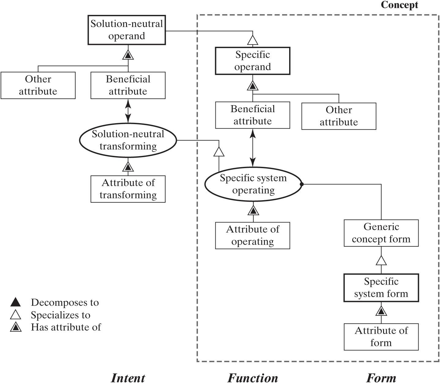
Figure 7.4 Template for deriving concept from solution-neutral functional intent.
There are five key ideas in Figure 7.4, implied by the five shapes with thicker borders. Table 7.3 shows the analysis of the systems we have been discussing. In the case of the pump, moving fluid is the solution-neutral function. Water, a type of fluid, is the specific operand, and pressurizing, which is one concept of operations of a pump, is done with a centrifugal pump. For bubblesort, the array is the solution-neutral operand, entries of the array are the specific operand, and sequentially sorting (in contrast with inserting) using bubblesort (rather than quicksort) is the concept.
Table 7.3 | Solution-neutral function and solution-specific concept for five systems
| Solution-Neutral Operand | Solution-Neutral Process | Specific Operand | Specific Process | Specific Instrument |
|---|---|---|---|---|
| Fluid | Moving | Water | Pressurizing | Centrifugal pump |
| Array | Sorting | Array entries | Sequentially exchanging | Bubblesort |
| Cork | Translating | Cork | Pulling | Screw |
| Traveler | Transporting | Traveler | Flying | Airplane |
| Book | Buying | Internet | Accessing | Home DSL connection |
Looking at all of the examples in Table 7.3 makes it clear that there is no single relationship between the specific operand and the solution-neutral operand, or between the specific process and the solution-neutral process, as discussed in Box 7.3.
Steps for Developing Concepts
The steps for developing the complete description of the concept are implicit in Figure 7.4: Identify the specific operand, whose change will satisfy the functional intent; identify the beneficial attribute of the specific operand whose change is associated with value; and so on. These points are summarized in Question 5a of Table 7.1.
The analysis of the concept for the two higher-complexity systems is shown in Table 7.4, using the approach of Figure 7.4. Transporting has now been specialized to the specific process of flying. “Flyer” is the dummy form, which is specialized to an airplane that is commercial. This is a case where the solution-neutral and specific operands are the same, but the process specializes. In simple language, the concept is as follows: a single traveler with light luggage flying in less than 2 hours on a commercial airplane.
Table 7.4 | Formulation of the specific function and form defining the concept of the transportation service and the home network. See Table 7.2 for the solution-neutral function.
| Question | Transportation Service | Home Network |
|---|---|---|
| Specific operand? | Traveler | Internet |
| Benefit-related attribute? | Location | Access |
| Other operand attributes? | Alone with light luggage | High-speed connection |
| Specific process? | Flying | Gaining (Accessing) |
| Attributes of process? | In less than 2 hours | Reliably |
| Generic concept form? | “Flyer” | “Accesser” |
| Specific form? | Airplane | Home DSL connection |
| Attributes of form? | Commercial | Inexpensive |
The home network case proceeds somewhat differently. The solution-neutral operand is book, but the specific operand jumps to network. Gaining access, or simply accessing, is the process, and reliable is the attribute of accessing. This is done by a dummy “accesser,” which specializes to an inexpensive home DSL network. In simple language, the concept is as follows: reliably accessing a high-speed Internet connection using an inexpensive home DSL network.
As we noted in Chapter 2, the operand-process-instrument construction we used to describe a system can be likened to the noun-verb-noun structure of human language. Notice that when the concept is described using the template of Figure 7.4, the concept is described by a full sentence. The instrument is the noun subject, and the attributes are adjectives. The process is the verb, and attributes of the process are adverbs. The operand is the object (grammatically speaking), and the attributes of the operand are adjectives in the predicate. Thus, a concept boils down to a sentence.
The idea of concept is very close to the idea of patterns in software. A software pattern is a “problem–solution pair in a given context.” [2] Looking at Figure 7.4, the “problem” is what here is called the solution-neutral functional intent. The “solution” is the concept.
Naming Concepts
There is no simple convention for naming concepts. Rationally, concepts should be named operand + process + instrument, and a few are, such as light + emitting + diode in Table 7.5. Examples of other conventions are shown in Figure 7.5 as well. Concepts are not normally named for just the operand, because it doesn’t contain enough information to describe a concept. In English, the ending “er” shows up to make a process sound like an instrument, but we don’t really express much more by calling something a mower than by calling it a mow.
Table 7.5 | Naming conventions for concepts
| Concept-Naming Convention | Operand | Process | Instrument |
|---|---|---|---|
| Operand-Process-Instrument | light | emitting | diode |
| data | storage | warehouse | |
| Operand-Process | lawn | mow | (er) |
| hair | dry | (er) | |
| Operand-Instrument | cork | (removing) | screw |
| fire | (burning) | place | |
| hat | (storing) | rack | |
| suit | (carrying) | case | |
| Process-Instrument | (food) | dining | room |
| (stuff) | carrying | case | |
| Process | (TV) | control | (er) |
| (image) | project | (er) | |
| Instrument | (head) | (covering) | hat |
| (food) | (serving) | table | |
| (person) | (carrying) | bicycle |
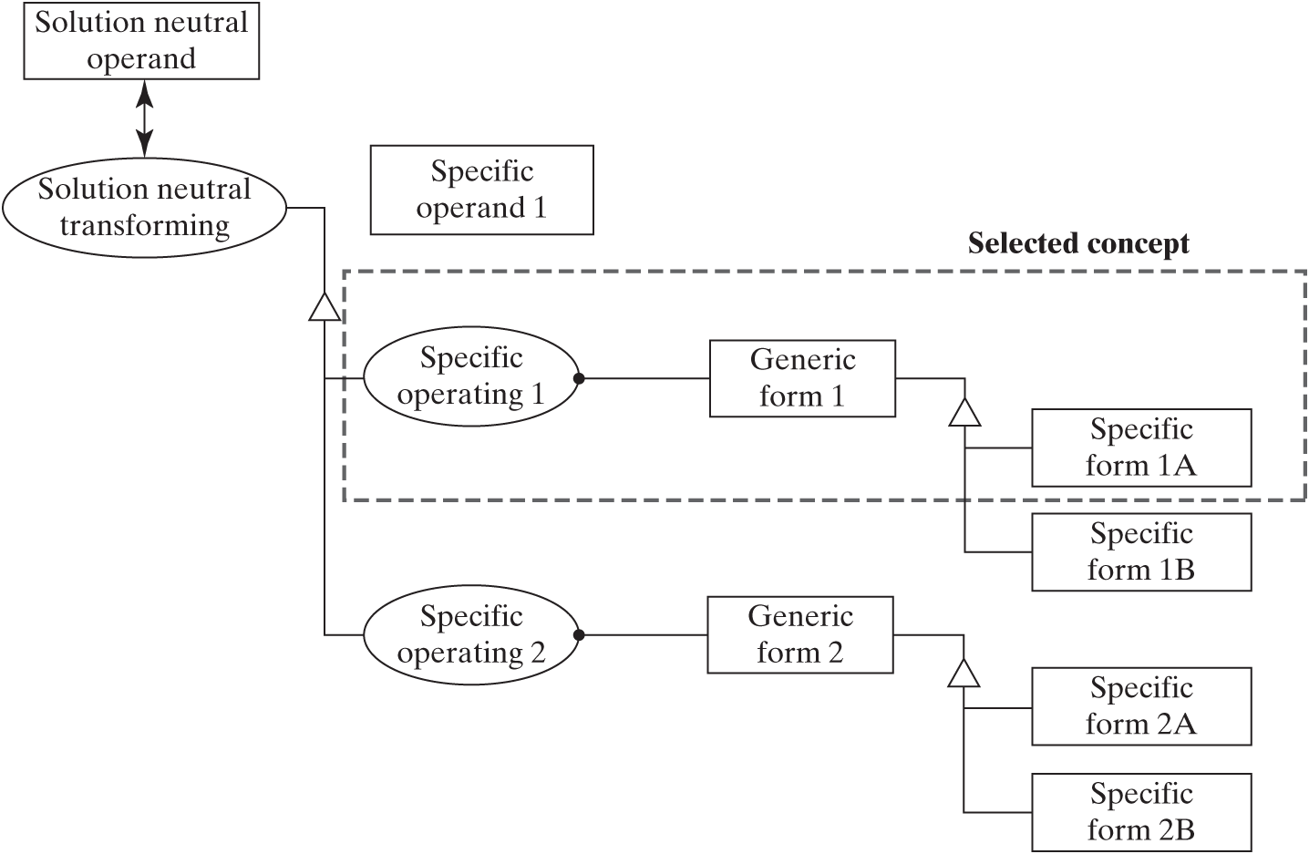
Figure 7.5 Tree showing the options among concepts, with different specific operating and specific instruments of form, but all with the same specific operand 1.
Sometimes a concept is named for an attribute of the process or instrument, as “wireless” was used for two different concepts at the beginning of the twentieth century and at the beginning of the twenty-first.
Sorting Alternative Concepts
Developing concepts is an open-ended creative process, and it is in the interest of the architect to have a rich set of ideas to select from.
Once the structured creativity or brainstorming phase of developing concepts is concluded, then the sorting and down-selecting begin. The process of deriving selection criteria based on stakeholder needs and product/system goals will be deferred to Chapter 11. In this section, we will discuss the process of sorting and organizing the possible concepts.
Figure 7.5 shows an OPM graphic that suggests an organization scheme for alternative concepts. First, all of the concepts that operate on the same specific operand would be organized on one page. Different concepts may in fact operate on different specific operands, while producing the same solution-neutral result. For example, if the solution-neutral statement for the pump is to move fluid, one option is pump water, but it could also be circulate air (increasing the rate of evaporation). The solution-neutral operand fluid could specialize to the specific operand water or air, as discussed in Box 7.3.
The graph in Figure 7.5 organizes the concept options into an operand layer, a process layer, and an instrumental form layer. In general, there are fewer operand options than process options, and fewer process options than form options, so this decision tree representation makes sense.
Figure 7.6 shows an example of a tabular version of the same decision tree as in Figure 7.5, specialized to the “centrifugal pump,” which is now just one of seven concept options in this non-exhaustive list. For water as an operand, there is a principle of operation of “pressurizing” that could be accomplished by a centrifugal pump or an axial flow pump. Alternatively, there is a different operating principle called accelerating, which can be done by a different kind of centrifugal pump or a jet ejector. Displacement pumps work on yet another principle. The same reasoning, applied to sorting in Figure 7.7, reveals three common principles of operation in sorting, each with several specific algorithms, which are one of the abstractions of form for computation.
Transporting the traveler is developed in Figure 7.8, where traveler is the only likely operand. There are a wide variety of specific processes for transporting, and it is a long-standing human endeavor. We limited the specific process list to flying, rolling, and floating, and then linked each to common instruments.
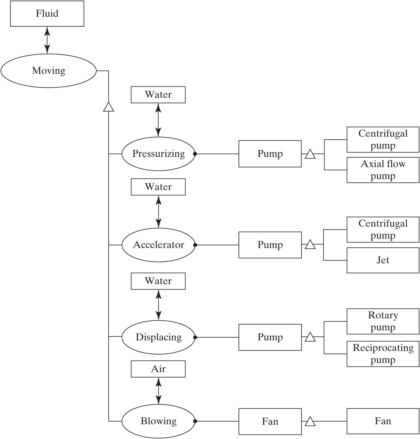
Figure 7.6 Solution-neutral function and solution-specific concept options for “pump” system.
Figure 7.9 shows the more limited option space for the “home network” example. In buying a book online, it is hard to avoid accessing the Internet, so here the options are only how you access: through various types of home connections, in public spaces, or at work.
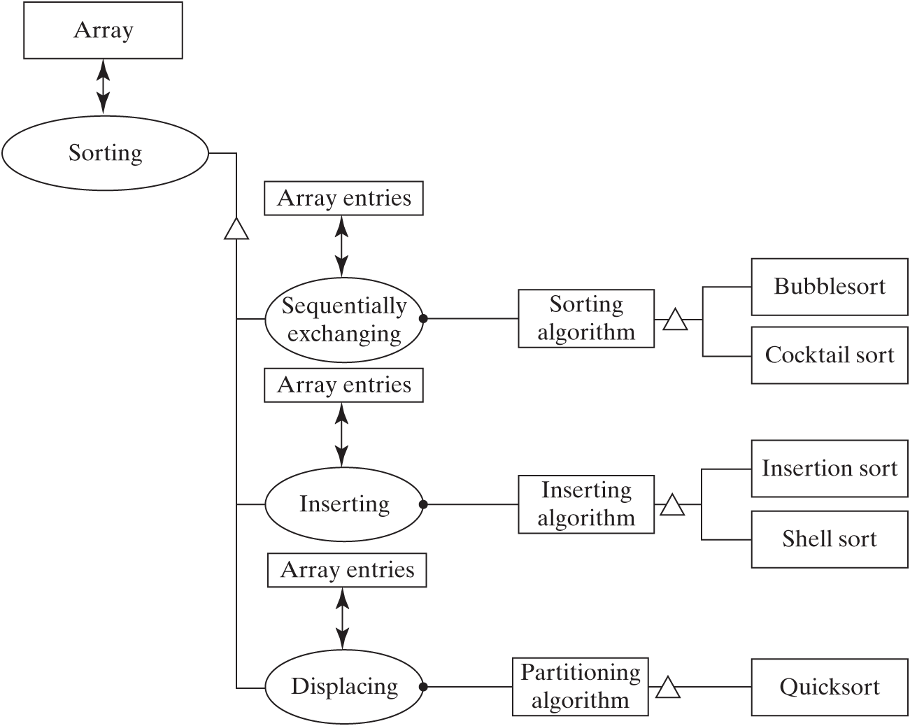
Figure 7.7 Solution-neutral function and solution-specific concept options for “bubblesort” system.
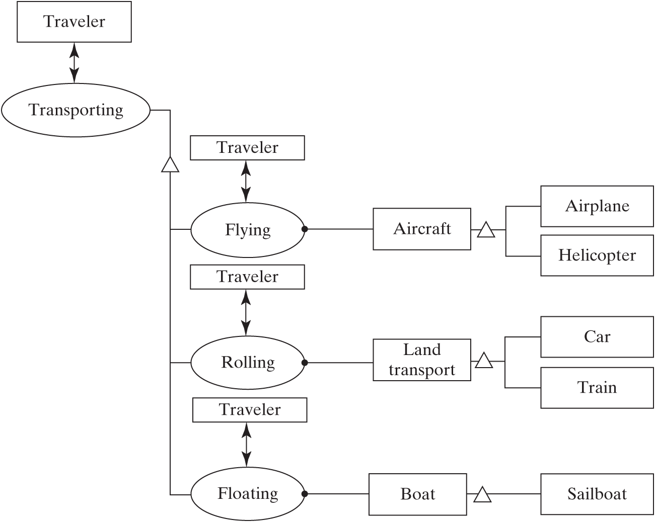
Figure 7.8 Solution-neutral function and solution-specific concept options for “transportation service” system.
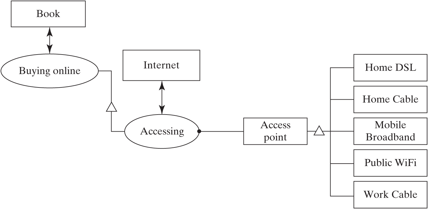
Figure 7.9 Solution-neutral function and solution-specific concept options for “home network” system.
It is important for the architect to develop a comprehensive view of the concept space prior to launching into the details of architecture, and thus answering the last item in Question 5a: “What are several other concepts that satisfy the solution-neutral function?”
Broader Concepts and Hierarchy
The analysis of concept alternatives focused on looking “downward” to increasing detail from the solution-neutral statement of the intent. However, we can also look “upward” to increasingly more general intent, just as we did with wine accessing. Why do we move fluid? Sort arrays? Travel? Buy books? This is a question of functional intent, and we have learned that solution-neutral intent is a hierarchy.
Maybe we move fluid to dry a basement. Why dry a basement? Maybe to improve the living conditions in a house. We should not be surprised that there is hierarchy in functional intent, just as there is hierarchy in built systems.
Figure 7.10 shows a hierarchic concept tree for the traveler. We have focused (for example, in Tables 7.2 and 7.4) on the level of a traveler traveling, specifically flying. But looking at the need statement in Table 7.2, we see a hint of why the traveler travels: something about visiting a client. In Figure 7.10 we notionally explore what led to the need to travel: to close a deal, by learning more about client preferences, by meeting the client (at her or his office), by traveling, by flying. At all the levels there are alternative concepts that could be pursued. For example, one might ignore the needs of the client and try to change the client’s mind. One might have a teleconference or study the client’s materials. One might meet the client at a conference or trade show.
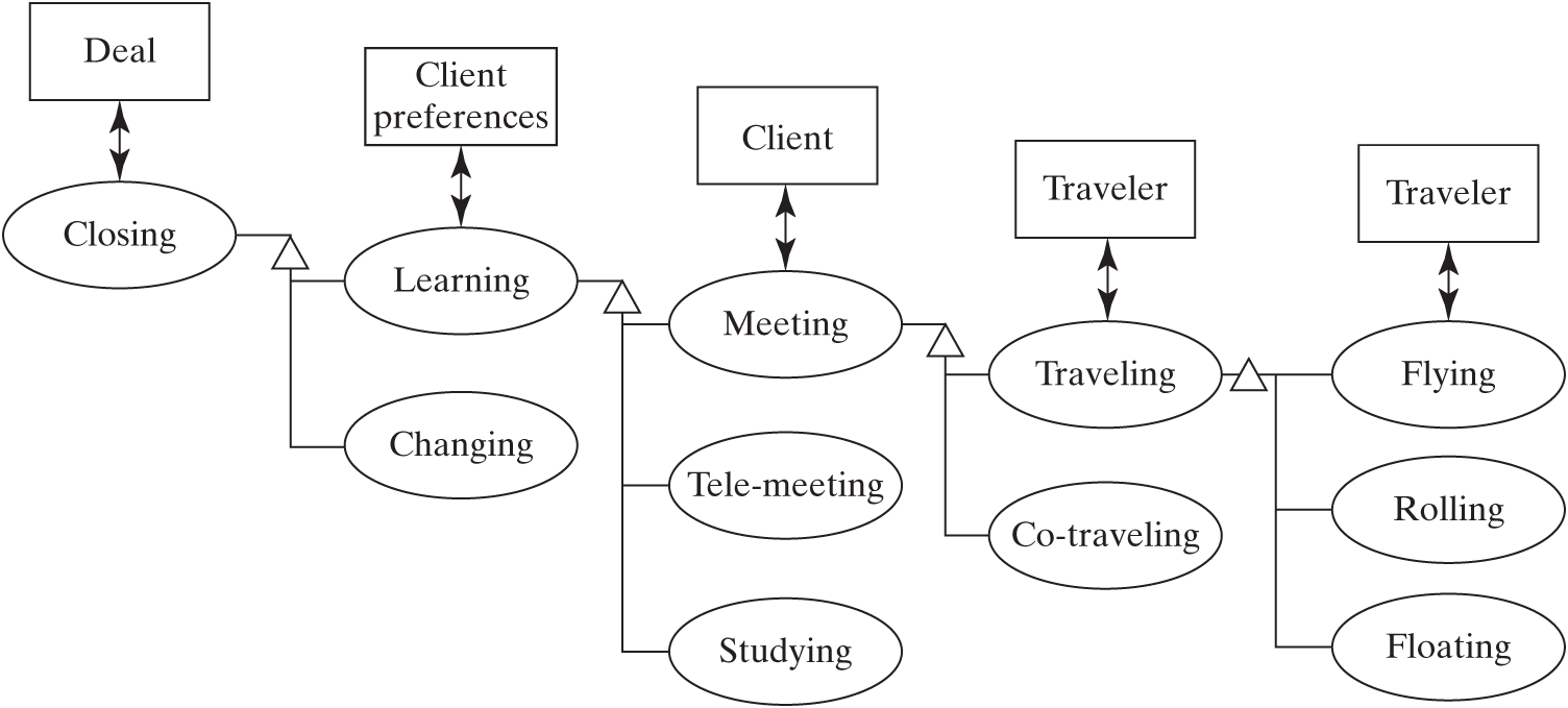
Figure 7.10 A hierarchy of intents and concepts leading to flying the traveler.
This hierarchy shows that the specific function at one level becomes the solution-neutral functional intent at the next level down the hierarchy. For example, learning client preferences is a specific function compared to the solution-neutral intent “deal closing,” but it then becomes the solution-neutral intent compared to the more specific “client meeting.”
Which of these is the right level at which to start examining the goals of the system? There is no right answer, and in fact it is very useful for the architect to understand the hierarchy of intent for the system “up” through one or two levels.
Figure 7.11 shows the similar hierarchy of intents and concepts for the home network. It begins with entertainment, specializes to reading books, which requires borrowing or buying books, which can be bought online, which leads to accessing the network. Understanding this hierarchy might identify new options, such as selling electronic books.
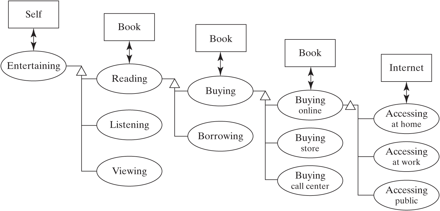
Figure 7.11 A hierarchy of intents and concepts leading to accessing the Internet at home.
In summary:
Concept is a system vision that maps function to form. Concept establishes the solution vocabulary and the set of design parameters. Concept rationalizes the details of the architecture and guides its development.
Concept is derived by specializing the solution-neutral operand and process to the specific operand and process, and to an abstraction of form (the specific instrument), as suggested in Figure 7.4.
There is no common convention for naming concepts, and the operand, process, and/or instrument may appear in the name.
Concept options should be developed and sorted to form a set that spans the possible functional concepts and instrument concepts.
Concepts sit in a hierarchy. The specific function at one level becomes the solution-neutral functional intent at the next level down the hierarchy. It is important for the architect to understand several levels of this hierarchy.