
8.4 Home Data Network Architecture at Level 2
We now present the home data network architecture at Level 2, as an example of what this method of architectural analysis can produce. Recall that the solution-neutral function of this system is to buy a book, and the concept is to do so by accessing the Internet using a DSL modem. The integrated concept involves a dedicated DSL modem, an integrated gateway and switch, a WAP connected to the switch by Ethernet, and a laptop connected to the WAP by WiFi (Table 7.8). A Level 1 architecture is shown in Figure 7.12.
Figure 8.5 shows the architecture at Level 2, following the route of an IP packet sent from a laptop on the home network until it leaves the local network bound for some external server or computer. We break the functional architecture into three layers: the Internet layer, the link layer, and the physical layer. The idea of layers in an architecture was introduced in Section 6.3.
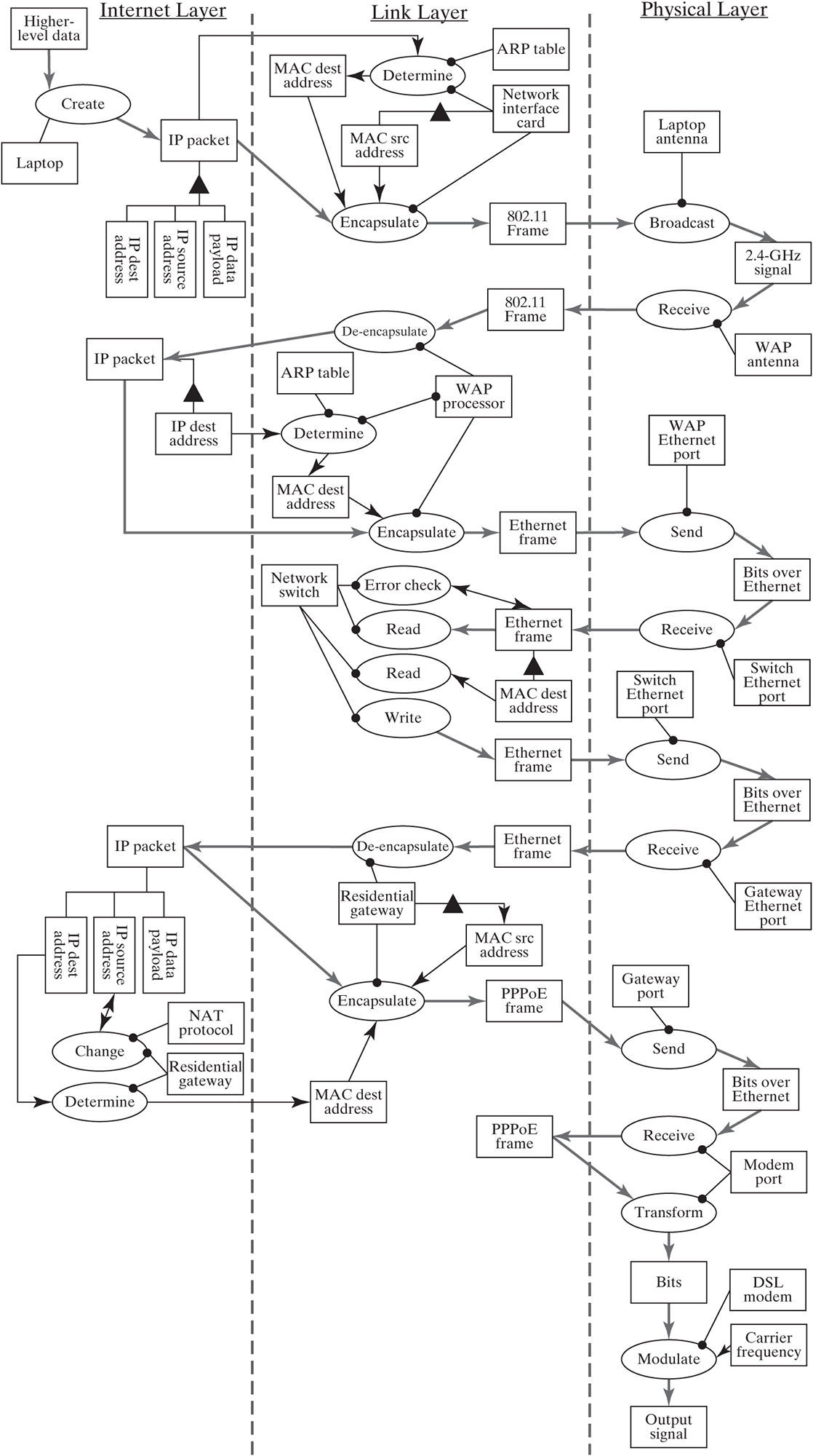
Figure 8.5 Architecture for the home data network at Level 2.
As shown in the form representation of the home network, data flow from the user’s laptop through its network interface card and then are broadcast via WiFi (2.4-GHz signal) and picked up by a wireless access point (WAP). From there, data travel through the Ethernet switch and are directed to the residential gateway/router. The router sends them to the modem, which then modulates the data onto a signal traveling out of the house via a phone line.
The functional path that the data follow (a description of what happens to the data at each step along their path out of the network) is much less straightforward. The source of this difficulty is that the network protocols are divided into layers. The purpose of a layered approach is to allow a network designer or IT manager to view the network through the lens of only a single layer, abstracting the functions of the other layers. This layered approach is common to network communication models, with the OSI seven-layer model and the five-layer Internet protocol suite being the primary examples. The three layers in our home network model are identical to the bottom three layers of the Internet protocol suite, with the application and transport layers excluded (the home data network does not play a major role in creating or managing data).
This layered approach gives modern networks many of their desirable emergent properties, such as scalability, robustness, and flexibility; unfortunately for us, it also makes it difficult to trace the functional pathway of data across multiple layers. However, we believe this “linearized” view of the network functional pathway is valuable, so we include the following description.
The first step along this path is the creation of an IP packet by the user laptop from some source of higher-layer data. The packet consists of a number of distinct elements, but we will focus on three: a source IP address, a destination IP address, and a data payload (error checking is another key element). The source address points to the laptop, and the destination address points to the server or computer where the IP packet is being sent (presumably to request data from a server or to upload data to be stored). The data payload contains the higher-layer data.
This packet (IP Layer) gets transformed into one or more frames (Link Layer), in a process known as encapsulation, to be transferred across the local WiFi link. Encapsulation into an 802.11 frame (WiFi protocol) adds media access control (MAC) source and destination addresses. MAC addresses encode the frame’s location and destination on the local network. MAC addresses are similar to IP addresses, except that they encode location within the “neighborhood” of the local area network and do not enable the routing functions that are the core of IP. The source MAC address is a static property of the laptop’s network interface card, whereas the destination address is retrieved from an address resolution protocol (ARP) table that maps destination IP addresses to destination MAC addresses.
The 802.11 frame(s) is (are) then sent wirelessly to the wireless access point (WAP) by modulating the bits of the frame onto a 2.4G-Hz radio signal and broadcasting this signal from the laptop antenna. This transfer occurs at the Physical Layer. Once received, the 802.11 frame is unpackaged by the WAP to reconstruct the IP packet. Because the WAP needs to know where to send the data next, it reads the IP destination address and sees that this destination is located through the residential gateway. It then encapsulates the IP packet into an Ethernet frame, setting the MAC destination address as that of the residential gateway.
The WAP then sends the frame toward the gateway by sending it via the Ethernet cable to the network switch. Again, this transfer of bits through a physical medium (in this case, copper wire) occurs at the Physical Layer. Once the frame reaches the switch, it is stored in a buffer, and the destination MAC address is read. Using this address and knowledge of the location of the residential gateway, the switch then writes the buffered frame to the link on which the gateway is located. In addition, the switch performs an error-checking function to ensure that the frame was read and transferred correctly.
Once the Ethernet frame reaches the residential gateway (again by way of a Physical Layer connection), it is again unpackaged to form the original IP packet. Here the gateway performs a function known as network address translation (NAT), wherein the source IP address is changed to the “public facing” IP address of the residential gateway from the “local” IP address of the laptop. This address change accomplishes two functions: It preserves IP addresses (with NAT, not every Internet-enabled device needs a unique IP address), and it adds an additional layer of security because the user device is not broadcasting its address across the wider network.
Once the IP address is set, the packet is encapsulated into a PPPoE (Peer-to-Peer Protocol over Ethernet) frame that allows the gateway to communicate with the Internet service provider on the Link Layer. This frame is then modulated by the DSL modem onto a high-frequency carrier signal that travels through the home phone line to the telephone company’s exchange center and then on to the ISP to be routed to its final destination.
In summary, the home data network can be expanded to Level 2 in a way similar to what occurs in the air transportation service. The home data network architecture with 24 internal processes and associated operands is represented by an OPM diagram (Figure 8.5). The operands and processes give a sense of the flow of data through the system. The instruments include both physical devices (laptop, switch, antenna) and informational objects (software and data tables). The Level 2 model enables us to judge the robustness of the Level 1 model and associated modularization.