6.5 Reasoning about Architecture Using Representations
Simplified System Representation
The view of the system architecture that we have developed may be too complete for many needs. Simplified or condensed versions of the representation may be adequate or even preferable, providing the right amount of information or providing it in a way more broadly understandable. Starting with the full representation of the system architecture (Figure 6.10), there are several approaches to producing a simpler rendition: Hide detail in abstractions, leave out detail, or project the system. The first approach is to create larger-scale abstractions to conceal details. Examining Figure 6.10, for example, we could create an abstraction for the motor assembly that includes the motor and shaft.
Another option is to simplify the representation of the system by leaving out some details. The procedural guidance here is to reflect on the important details in the hierarchy, applying the Principle of Focus (Box 2.6), and preserving insight into the value pathways (operands and processes) while simplifying elsewhere.
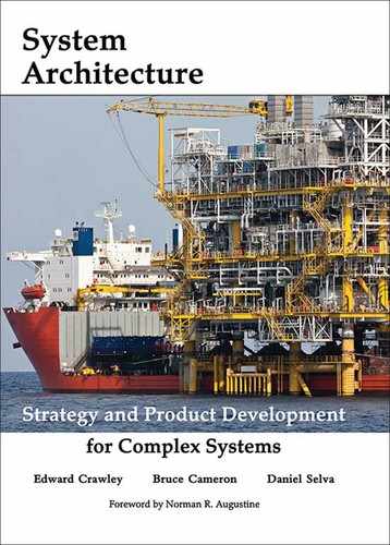
A simplified pump architecture created in light of these guidelines is shown in Figure 6.15. Comparing Figure 6.15 with Figure 6.10 suggests that it may be easier to understand the pump architecture with the simplified drawing. The value pathway is preserved, but there is still a suggestion that the cover and housing manage the non-ideal movement of the operand. The role of the motor shaft in supporting and driving the impeller stands out more. The key operand interfaces have been retained, as well as one of the supporting interfaces. We will use this simplified pump example for the remainder of the chapter.
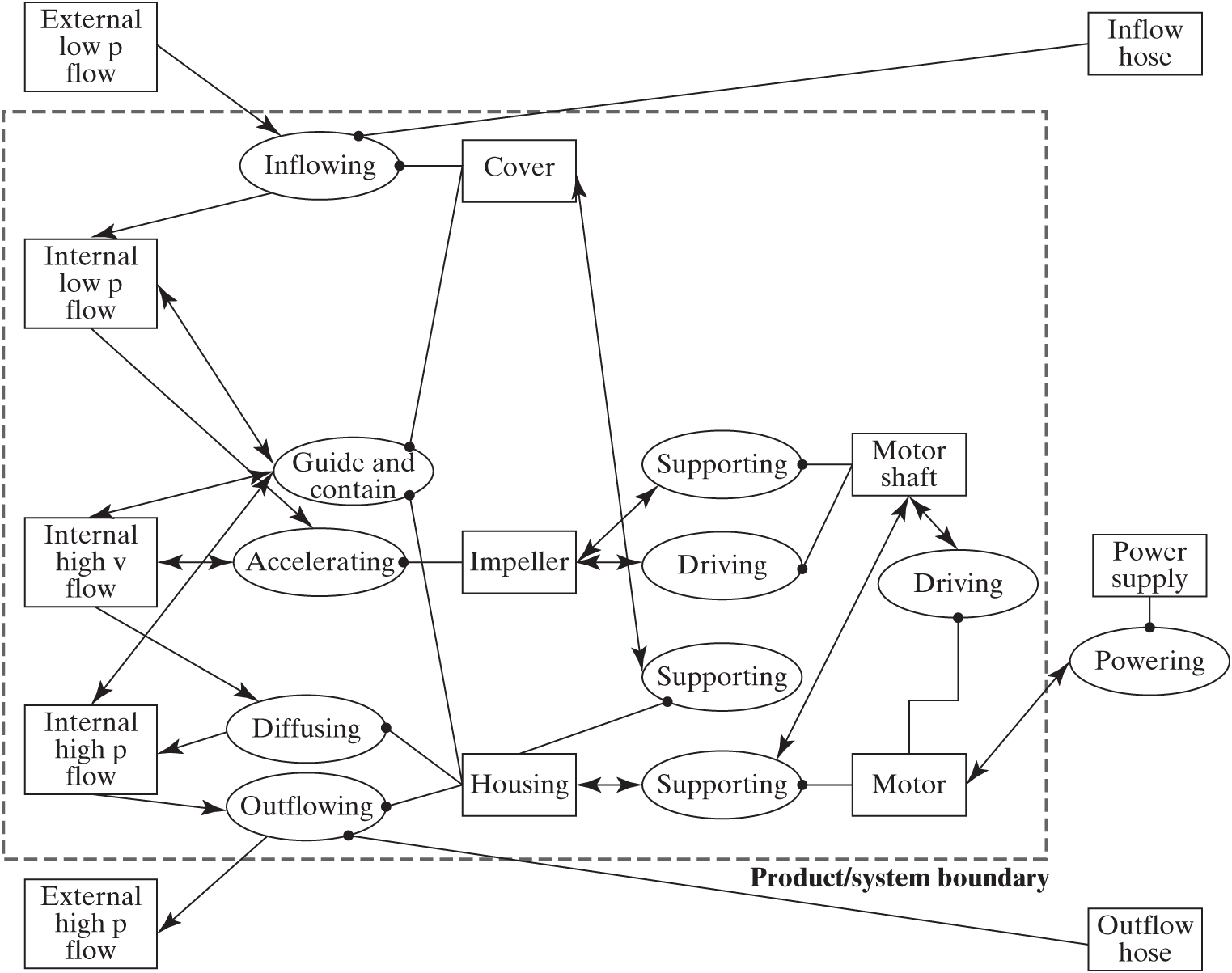
Figure 6.15 Simplified pump system architecture.
The simplified architecture of the pump can also be represented by an array. In Box 5.10, the process-operand array (PO) was introduced. By extension, we can define a process-form array (PF), which represents the relationships between the processes and their instruments. Combining these two ideas, we develop the array | PO PF | of Table 6.2, which contains exactly the same information as Figure 6.15.
Table 6.2 | System architecture of the simplified pump. Internal and external processes are shown on the left, internal and external operands and internal and external instruments on the top.
| O1 | O2 | O3 | O4 | O5 | motor shaft | power supply | ||||||||
|---|---|---|---|---|---|---|---|---|---|---|---|---|---|---|
| internal low pressure flow | internal high velocity flow | internal high pressure flow | external low pressure flow | external high pressure flow | cover | impeller | housing | motor | pipe (in) | pipe (out) | ||||
| P1 | inflowing | c' | d | I | I | |||||||||
| P2 | accelerating | d | c' | I | ||||||||||
| P3 | diffusing | d | c' | I | ||||||||||
| P4 | outflowing | d | c' | I | I | |||||||||
| P5 | guiding/containing | a | a | a | I | I | ||||||||
| P6 | supporting (rotating) | a | I | |||||||||||
| P7 | driving (shaft) | a | I | |||||||||||
| P8 | supporting (housing) | a | I | |||||||||||
| P9 | supporting (motor) | a | I | a | ||||||||||
| P10 | driving (motor) | I | a | |||||||||||
| P11 | powering | a | I |
In Table 6.2, the shaded section represents the value-related processes. The graphical representation (Figure 6.10) has the advantage of showing the partitioning of the system into layers a bit more visually, whereas the matrix representation (Table 6.2) is more compact and allows for computation, as we will see shortly.
Projected System Representations
If there is still too much information in the simplified representation, another option is to condense the system by projection, as discussed in Section 3.6. Box 5.11 presented a projection of operands onto processes. Here we explore two additional types of projections: onto objects and onto form.
The starting point of this procedure is to construct a DSM as shown in Table 6.3. Box 5.11 defined the arrays PP, PO, OP, and OO. The PF array is defined above, and the FP array is derived from the PF array by analogy, using the procedure in Box 5.11. The FF array is generally a diagonal with an identifier for each element of form. This array does not contain the structural connections discussed in Section 4.4. The OF and FO arrays are generally zero, because the operands do not usually have a connection directly to objects of form; there is always an intervening process.
Table 6.3 | The full system DSM of a system architecture, an N-Squared matrix with the processes, operands, and objects of form shown on both axes
| Process | Operand | Form | |
|---|---|---|---|
| Process | PP | PO | PF |
| Operand | OP | OO | OF |
| Form | FP | FO | FF |
Projection onto Objects
In the projection of processes onto objects, the operands and instruments are shown explicitly, and the processes become links. The advantage of this projection is that to many viewers, the objects are more concrete. However, those less familiar with system architecture may require some explanation of the idea of operand objects. Such a projection onto objects for bread slicing is shown in Figure 6.16.
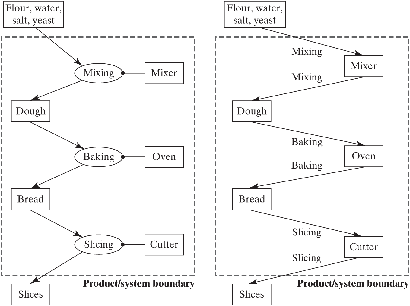
Figure 6.16 Projection onto the objects of making sliced bread.
Figure 6.17 shows the schematic for “hand drawing” the projection onto objects from an OPM diagram of the full architecture:
Isolate each object.
Follow links from the object (operands or instruments) to the connecting process and then to the next connecting object.
Represent this object-process-object path as a structural relationship between the two objects, and label it.
Figure 6.17 Schematic projection of the system architecture onto the objects.
The formalism of matrix projection for this case is to compute the relationships between the operands (OP × PP × PO), the elements of form (FP × PP × PF), and the cross terms (OP × PP × PF) and (FP × PP × PO). The way in which they would be constructed if we were “hand drawing” the projection is shown in Figure 6.21. The final array representing the projection would read
The terms with primes could be retained, or the primed terms could be dropped to more explicitly show causality.
The OPM diagram projected onto objects is shown for the value stream objects of the simplified pump in Figure 6.18. The five operands are connected by the processes. These same processes connect the operands to the elements of form.
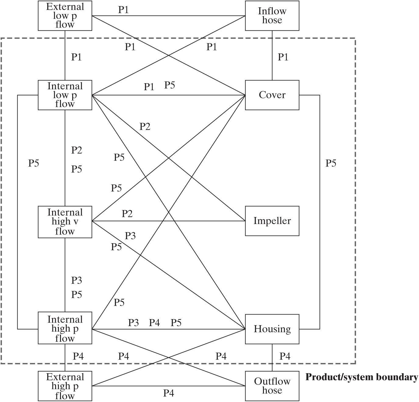
Figure 6.18 Projection of the value stream of the simplified pump system architecture onto the objects. (See Table 6.2 for legend of the processes.)
All of the architectural information is captured in Figure 6.18 by the objects and the linking processes. You can reason from operands through the process links to instruments to understand function. You can also reason from form object to form object to understand the amount of functional coupling between the elements of form.
Projection onto Form
The entire system architecture can also be projected onto the most tangible elements, the objects of form. This projection makes the entities appear very simple but stores a lot of information on the links. Figure 6.19 shows the projection onto form of the sliced bread architecture. Now the links between objects of form encode the previous process, the connecting operand, and the following process.
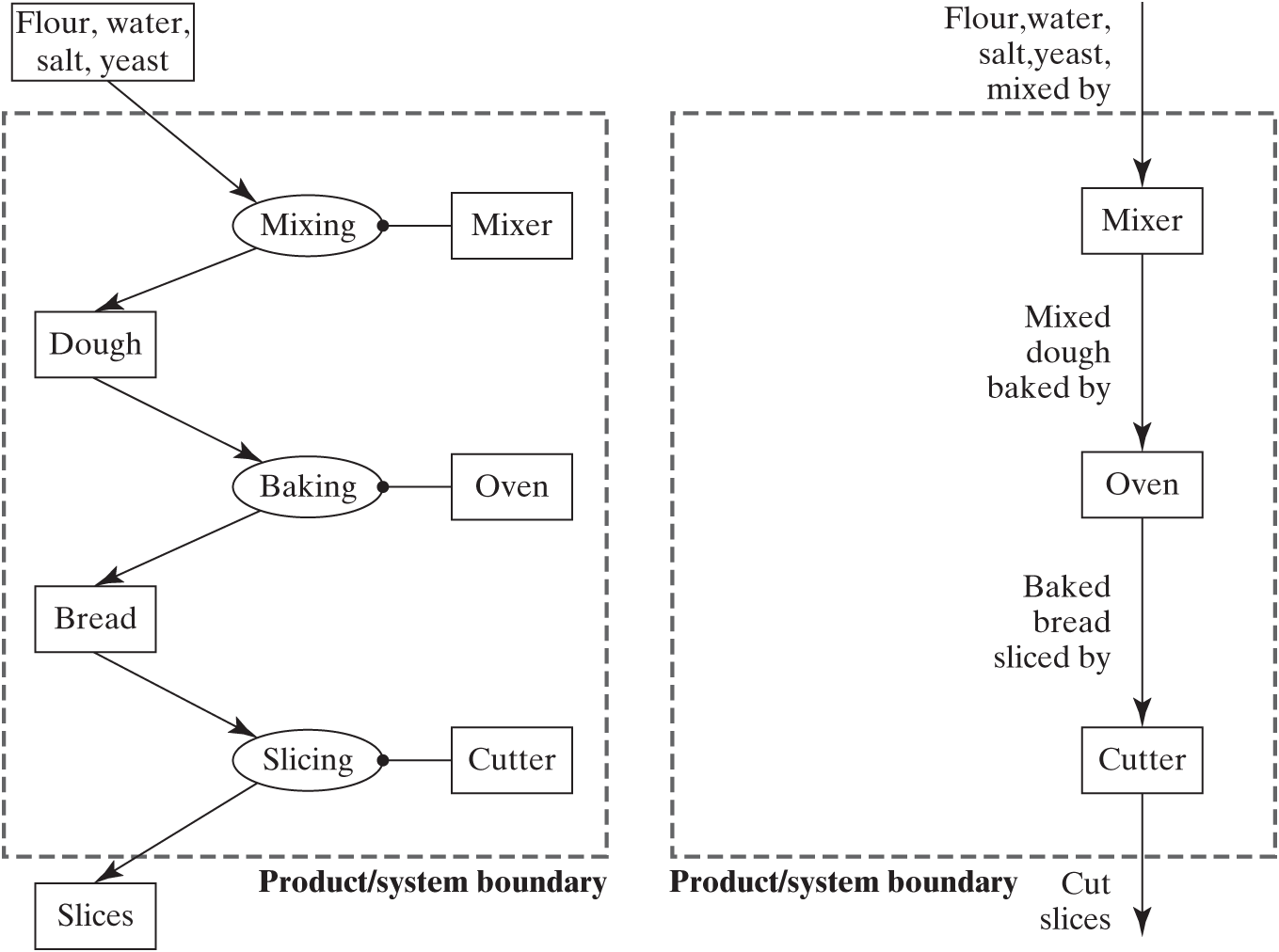
Figure 6.19 Projection onto the form of making sliced bread. (Compare with Figure 6.16.)
The schematic for developing this information is shown in Figure 6.20. Now there are two parts of the projection. The links between elements for form through a single process are simple. However, in order to reach the operands, you have to go from an object of form to a process, then to an operand, then back to a process, and then back to an element of form (FP × PP × PO × OO × OP × PP × PF). The sum of these two resulting arrays will form an N-Squared matrix that corresponds to the most common DSM used for products, with elements of form on two sides.
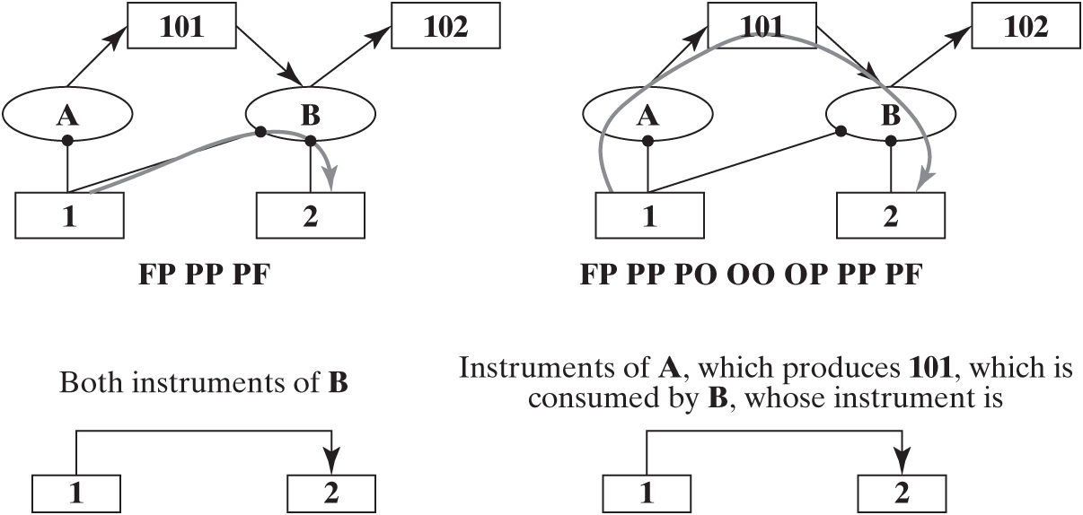
Figure 6.20 Schematic projection of the system architecture onto the form.
The projected arrays for the simplified pump can be calculated from the information in Table 6.2 and are shown in Figure 6.21. The links between objects of form through processes are quite simple to understand. The operand links are more complex and are marked with the operand that forms the link, but not the two processes.
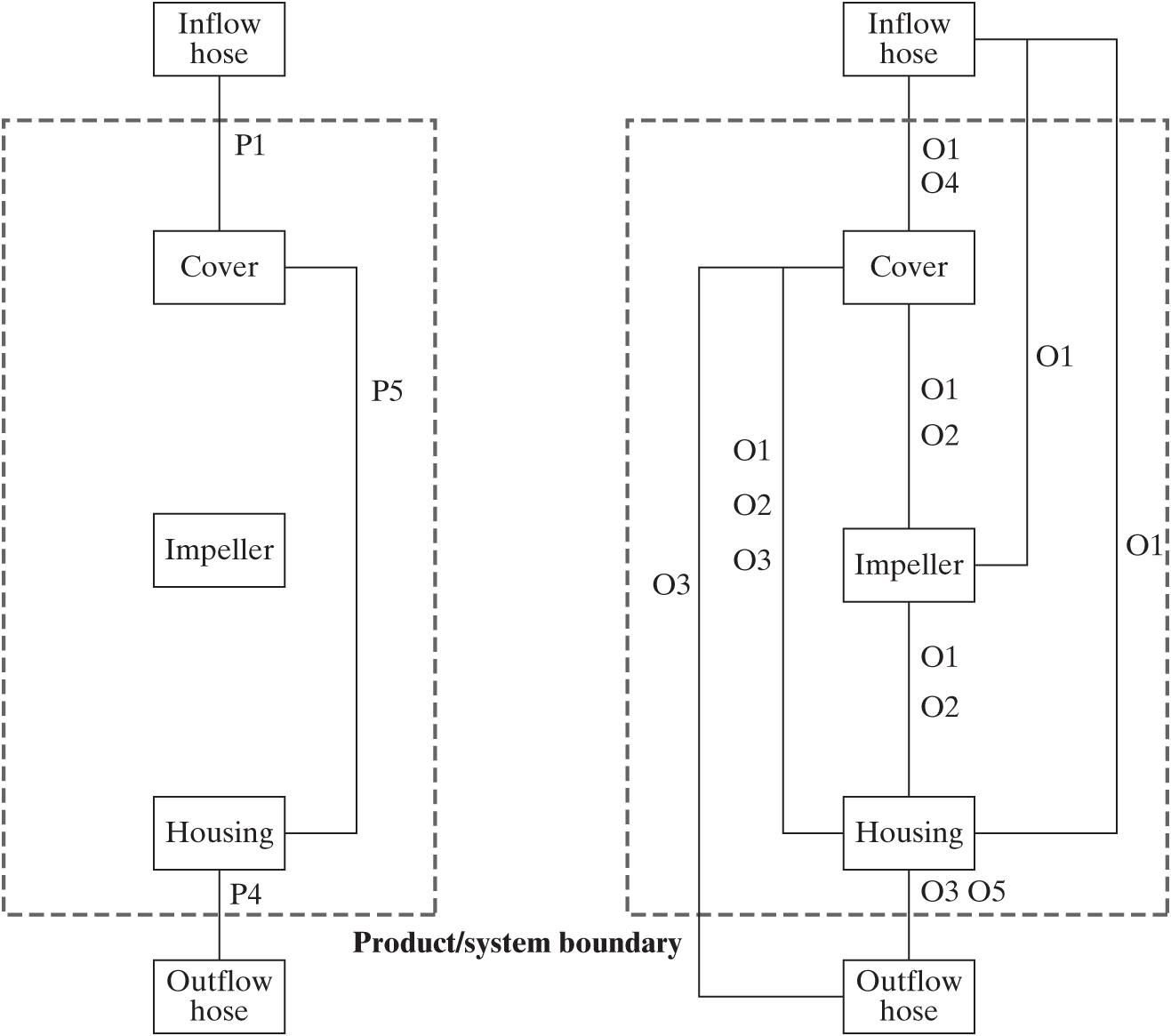
Figure 6.21 Projection of the value stream of the simplified pump system architecture onto the form. FP × PP × PF is shown on the left, and FP × PP × PO × OO × OP × PP × PF on the right. (See Table 6.2 for more information.)
In some ways, Figure 6.21 is the most compact representation of a system. The instrument objects are very concrete, and the information is sufficiently abstracted that most non-experts can understand it. Something similar to Figure 6.21 can be constructed with a SysML internal block diagram if item flow links are used. Sometimes in making models, the operand interactions between the elements of form are represented by classes of interactions such as those shown in Table 6.4.
Table 6.4 | Classes of interactions for operand interactions
| Matter | Mechanical | Mass exchange | Passes flow to |
| Force/momentum | Pushes on | ||
| Biochemical | Chemical | Reacts with | |
| Biological | Replicates | ||
| Energy | Work | Carries electricity | |
| Thermal energy | Heats | ||
| Information | Signal | Data | Transfers file |
| Commands | Triggers | ||
| Thought | Cognitive thought | Exchanges ideas | |
| Affective thought | Imparts beliefs |
In summary:
The representation of an architecture that explicitly contains operands, processes, and objects of form has the advantage of capturing and explicitly showing all of the information about the system, but it produces an image or matrix that is quite complex. Sometimes the representation can be simplified or abstracted.
The architecture can be projected onto the operand and form objects. This produces a diagram that is simpler and is very useful to the architect, but it requires an understanding of the role of operands.
The architecture can be projected onto just the objects of form, producing the most compact diagram, understandable by all, but with a lot of information stored on the links.