12
Simple Two-way Arbiters
One of the goals of this chapter is to show that the MUTEX and Sync elements, studied in the previous chapters, can be used to build an arbiter of any complexity. For example, MUTEX and Sync are required in two different typical situations which are described in Sections 12.2 and 12.3. Section 12.1 first introduces the basic concepts and conventions used throughout the chapter: requests, grants, channels and protocols.
12.1 BASIC CONCEPTS AND CONVENTIONS
As described in Chapter 11, an arbiter is reactive to input requests coming from clients and produces output grants returned back to the clients. Because requests and grants are typically functionally tied into pairs, we use the concept of channel. A channel, which couples a request with a grant, constitutes a means of communication between the arbiter and a client in a bidirectional way (Figure 12.1). Similarly, communications between the arbiter and resources are organized using channels.
The communication behaviour of a channel can be defined using a protocol, called the handshaking protocol, which defines signalling and causality rules. Many different protocols exist. Only two of them are considered in this chapter because they are common and represent two general classes of protocols: those based on transition signalling, and those based on level signalling.
Figure 12.1 Coupling requests and grants into channels. Chn = (Reqn, Grn).
12.1.1 Two-phase or Non-return-to-zero (NRZ) Protocols
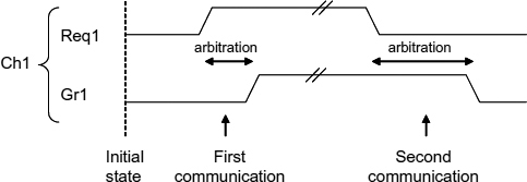
With this class of protocols, signalling is performed using signal transitions. In other words, only the occurrence of an event on a signal wire matters in this protocol, regardless of the initial and next level of the signal, hence its name non-return-to-zero (NRZ). Figure 12.2 describes a two-phase protocol for channel Ch1 as an example. Let us consider signals Req1 and Gr1 initially reset to zero (low level) by the client and the arbiter respectively. Then, a zero-to-one transition occurs on Req1 when client 1 is asking for arbitration. After processing the requests, the arbiter eventually issues a grant to client 1, by means of a zero-to-one transition on signal Gr1. This completes the two-phase protocol. The next communication will be using one-to-zero transitions (Figure 12.2).
It should be noted that the arbiter and the client must meet the following correctness conditions. Client 1 is not allowed to issue another request until the arbiter has responded with a grant. In the same way, the arbiter is not allowed to issue another grant until it has received a request.
Figure 12.2 Two request/grant handshakes on channel Ch1 using a two-phase protocol.
Figure 12.3 Two request/grant handshakes on channel Ch1 using a four-phase protocol.
12.1.2 Four-phase or Return-to-zero (RTZ) Protocols
This class of protocols uses level-based signalling as described in Figure 12.3. It is also known as a return-to-zero (RTZ) protocol. In the initial state, Req1 and Gr1 are both reset to zero by the client and the arbiter respectively. The communication starts when the client issues a request by setting Req1 to one. The arbiter then acknowledges the request by setting Gr1 to one. This completes the first two-phases of the protocol. Now starts the return-to-zero phase. In response to the setting of Gr1, the client resets Req1, and in response to Req1 the arbiter resets Gr1, which completes the four-phase protocol (back to the initial state).
It should again be stressed that for correct behaviour the client and arbiter must both respect the protocol rules. Req1 (Gr1) must remain stable at one or zero until Gr1 (Req1) has changed its state.
In the above protocols we assumed that the indication that the client has finished using the resource, i.e. the action that is often called the release of the resource is communicated on a separate channel, for example, the channel connecting the client directly with the resource. It is therefore not part of the arbitration procedure, which is a convenient way to separate concerns. However, sometimes people design arbiters in which the release action goes via the arbiter. For example, in the case of two-phase signalling, such an action uses an additional wire in the channel between the client and the arbiter (cf. signal Done in an RGD arbiter described in the next section). In the case of four-phase signaling, the release is often associated with the return-to-zero of the Req1 signal from the client. This happens often when a two-way or multi-way MUTEX is used as an arbiter itself. In the remainder of this chapter, we will assume the client to communicate the release action directly to the resource, unless it is specified otherwise.
12.2 SIMPLE ARBITRATION BETWEEN TWO ASYNCHRONOUS REQUESTS
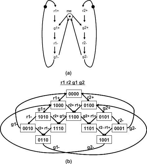
Let us first revise the behaviour of a simple MUTEX element introduced in the previous chapters. The MUTEX, which can itself be used as a two-way arbiter, is described by the STG shown in Figure 12.4(a). The behaviour of this STG can be understood with the aid of the corresponding reachable state graph. In the STG, the initial marking contains a single token (i.e. single resource) in the place labelled me (mutual exclusion place). This token allows only one transition, either g1+ or g2+ (but not both!), to fire when both r1+ and r2+ have fired. The state graph clearly demonstrates that the arbiter model meets the requirement of mutual exclusion between the two grants, because although both transitions g1+ and g2+ are enabled in the state with the encoding 1100, only one of them can fire (disabling the other transition). A place such as me is often called arbitrated choice (cf. controlled choice in the following examples).
Figure 12.4 A two-way MUTEX (r1 and r2 are requests and g1 and g2 are grants): (a) STG; (b) corresponding reachable state graph.
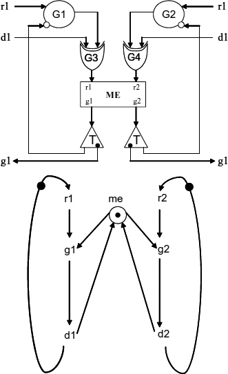
Figure 12.5 Request–Grant–Done (RGD) arbiter: (a) schematics; (b) STG specification.
The MUTEX uses the four-phase signalling on its request-grant pairs. All subsequent arbiter designs can be built on the basis of the MUTEX element. One such component, which is often itself a primitive element in many two-phase designs, is an RGD (Request–Grant–Done) arbiter, shown in Figure 12.5(a). Its input–output behaviour is described by the STG shown in Figure 12.5(b). Note that since this is a two-phase system the signal labels of transitions have no sign symbols.
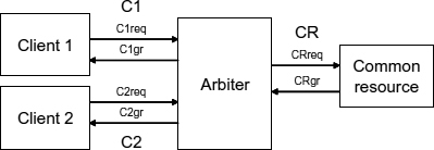
Consider now a typical arbitration situation when choice is made between two clients, C1 and C2, who may request a unique common resource CR. This situation is represented in Figure 12.6, where the channel and signal names are defined. The arbiter must guarantee that one and only one client is accessing the resource, and that the handshake protocols are correct when a client accesses the common resource.
Figure 12.6 Basic architecture of a system enabling two clients C1 and C2 to safely access a common resource CR.
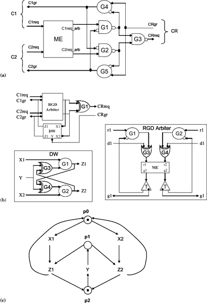
It is clear that clients C1 and C2 are in competition, via their communicating channels, when they both issue requests on signals C1req and C2req independently of each other. They have to be ordered in time in such a way that only one of them is chosen to be granted, thereby satisfying the property of mutual exclusion. Solving this problem requires a MUTEX element to decide between the two asynchronous requests and produce two mutually exclusive signals, C1req-arb and C2req-arb, to indicate the choice made. It is crucial that, once the decision has been made the MUTEX is not allowed to ‘change its mind’. Thus, because C1req-arb and C2req-arb are mutually exclusive, they can safely be used to control the communication protocol. Figure 12.7(a) describes the arbiter's schematic for the four-phase protocol, in which gates G4 and G5 are Muller C-elements.
Figure 12.7(b) shows how a two-phase arbiter is built. The latter involves a relatively larger circuit, consisting of an RGD arbiter and a 2-by-1 Decision–Wait element [93] (also known as JOIN [94]). The RGD arbiter itself uses a MUTEX as a building block, as well as two toggles, two C-elements and two XOR gates. The behaviour of a Decision–Wait (DW) element is shown in Figure 12.7(c). It shows a nondeterministic choice (modelled by place p0) between events on inputs X1 and X2. Place p1 models controlled choice, i.e. only one of the two transitions z1 or z2 is enabled, due to the fact that either arc (x1, z1) will have a token or arc (x2,z2). When the DW element is used to implement a two-phase arbiter, shown in part (b), a nondeterministic (from the point of view of DW element) choice is resolved by the RGD arbiter, whose grant outputs are connected to inputs x1 and x2 of the DW element. Place p2 is an example of a so-called merge place, i.e. only one token arrives in it either after firing z1 or z2, but never both.
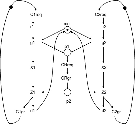
The composite behaviour of the two-phase arbiter solution is described by the STG shown in Figure 12.8.
Figure 12.7 MUTEX-based arbiters: (a) for four-phase protocol; (b) for two-phase protocol; (c) STG for Decision–Wait.
Figure 12.8 STG specification of the two-phase arbiter.
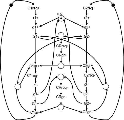
The behaviour of the four-phase one is shown in Figure 12.9. Let us, for example, examine the latter in more detail.
Assume that the request C1req from client C1 wins the arbitration. The MUTEX element then sets C1req-arb (transition g1+ fires) to one and maintains C2req-arb (i.e. grant g2) at zero until C1req is reset (transition r1-fires). Then, gate G1 and G3 fire and CRreq is set to one which issues a request to the common resource. Gate G4 is now enabled to fire as soon as CRgr is set to one. So, G4 fires and client C1 is granted (C1gr is set to one) which completes the two first phases of the protocol. Note that gate G2 is inhibited by C1gr (inverted input).
Now, C1req is reset by the client, C1req-arb (g1) is reset as well. G1 and G3 fire thereby resetting CRreq. At the same time, if C2req (r2) is one, the MUTEX may set C2req-arb (g2). G2 is still disabled, which postpones the request propagation through gate G2. CRgr is eventually reset and C1gr is reset, which on one hand completes the handshaking protocol on channel C1 and on the other hand opens G2 and the propagation of the request to the common resource. G2 and G3 fire, CRreq is set and another handshaking protocol starts on channel CR, which now communicates with channel C2.
Figure 12.9 STG specification of the four-phase arbiter.
Finally, note that MUTEX is the key element which ensures mutual exclusion between the internal signals C1req-arb and C2req-arb. As long as this is guaranteed, the other gates maintain the proper signalling between the elected client channel and the resource channel, following the channel protocols.
12.3 SAMPLING THE LOGIC LEVEL OF AN ASYNCHRONOUS REQUEST
Another typical conflict resolution situation happens when there is a need to determine, or probe, whether a client issues a request or not. To do so, one needs to sample the logic value of the request signal which is asynchronous to the sample command. Synchronization is then required to determine if the level of the asynchronous request signal is zero or one. The reader may refer to previous chapters to explain the idea of a synchronizer in detail. For the purpose of carrying out synchronization, one could use one of those synchronizers. However, under certain assumption about the protocol of interaction between the environment and the synchronizer, there is actually a possibility to build a synchronizer from a MUTEX element. This solution is shown in Figure 12.10.
Figure 12.10 Sync, a synchronizer built around a MUTEX.
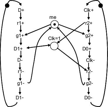
The behaviour of this circuit, called Sync, is described by the STG shown in Figure 12.11. Basically, the circuit arbitrates between two rising edges of the data input D and the clock input Clk. If D wins, the circuit then waits for the arrival of the Clk before it responds with the rising edge on output D1, thereby indicating that the data is equal to one. If Clk wins, then the circuit responds with the setting of D0, thus saying that the data is equal to zero. The completion of the four-phase signalling in either case is based on the reset of either data input (for D1) or the clock input (for D0). This circuit is therefore similar to a MUTEX, with respect to following the four-phase handshake signaling on pairs (D,D1) and (Clk, D0) except that the former is enhanced in its setting phase by the condition Clk = 1 when issuing the response on D1. Note that this STG uses the so-called read arc (dual-headed) which connects the Clk = 1 place with transition D1+. The ‘read-only’ meaning of such an arc is in the fact that D1+ requires a token to be present in place Clk = 1, but when D1+ fires this token is not consumed from this place. This place, however, has normal ‘produce’ and ‘consume’ relationships with transitions r2+ and r2, respectively.
Figure 12.11 STG describing the behaviour of Sync.
Let us compare this circuit's behaviour with that of a more general type of synchronizer. This circuit, being speed independent (unlike the common synchronizer with a ‘free-running’ clock), assumes that the probing of signal D by the Clk input is only done when signal D is either stable in zero or in its rising mode, i.e. going from zero to one. Furthermore, it is assumed that this signal is only allowed to go back to zero after it has been eventually registered as a winner by the circuit. This is ensured by the four-phase handshake between D and D1. In other words, D is required to be persistent and monotonic.
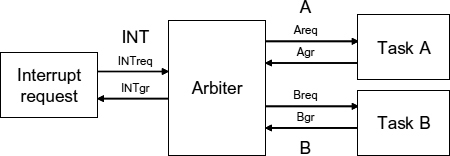
Let us now consider a typical example of usage of a Sync element in an arbitration context. Consider a system which can be interrupted by a client named ‘Interrupt Request’. The system normally performs task A in a loop, but every time the client ‘Interrupt Request’ is sending a request, the system inserts the execution of task B in the execution flow. Without loss of generality, assume that the execution of a task is performed by accessing the corresponding resource through a given channel. Then, the system's architecture can be described as in Figure 12.12.
The arbiter keeps running task A by communicating through channel A in a loop. Whenever ‘Interrupt Request’ sends a request through channel INT, the arbiter eventually responds to it by executing task B via the communication channel B.
Figure 12.12 Basic architecture of a system with arbitration in the interrupt handling context.
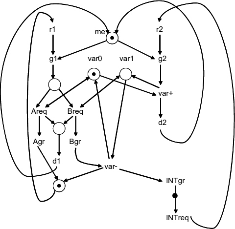
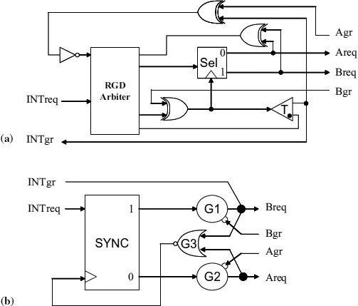
To solve this problem we can again provide two kinds of solutions, one for the two-phase protocol and the other for four-phase. The STG describing the two-phase solution is shown in Figure 12.13, and the corresponding circuit in Figure 12.15(a). This solution uses an RGD arbiter to resolve arbitration between the INTreq and the polling signal, Agr, the grant part of the A channel. Normally, if there is no event on INTreq, every time Agr occurs, it wins arbitration via g1, which causes a response on Areq because an interrupt flag, var, would be in a zero state. If between two adjacent polling requests on A there is an outstanding event on INTreq, the latter would cause the RGD arbiter to issue a grant on g2, thereby causing the interrupt flag var to be set to one, after which the RGD arbiter is released by signal d2. Then, upon the next arrival of the polling event Agr, the g1 grant would trigger the alternative route in the Sel element, namely the one leading to Breq. As soon as an event Bgr is returned from Task B, it toggles the interrupt flag var back to zero, followed by the response INTgr and the production of the new polling event, acting as a proxy of Agr.
Observing the STG in Figure 12.13, we can notice the read arcs between place var0 (for the value of flag var = 0) and transition Areq, and place var1 and Breq. The token between these two mutually complementary places is toggled by transitions var+ and var−.
Figure 12.13 STG specification of the two-phase Sync-based arbiter.
Figure 12.14 Specification of the four-phase Sync-based arbiter.
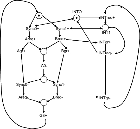
The four-phase solution is described by the STG shown in Figure 12.14, with the corresponding circuit in Figure 12.15(b). Here, because the system is based on levels rather than events, the arbiter has to check whether INTreq is high or not in order to determine if it has to perform a handshake on channel B or perform a handshake on channel A. A Sync block is therefore required to safely sample signal INTreq as shown in Figure 12.15(b). In order to represent the condition associated with the state of signal INTreq, the STG model again uses two complementary places INT0 and INT1 and read arcs controlling the enabling of transitions Sync0+ and Sync1+.
At reset, signals Bgr and Agr are zero and both Muller C-elements G1 and G2 are reset. Therefore, the output of the NOR gate G3 is set and INTreq is sampled by the synchronizer SYNC. Normally, if INTreq is low the SYNC block responds through its output 0, thereby causing a request on Areq through G2, followed by the reset of G3. This is followed by the reset-to-zero phase on the A channel. Otherwise, if INTreq is high, the SYNC block replies through its output 1, it triggers G1 to perform handshakes on both INT and B channels. When they complete INTreq is sampled again, and so on.
Figure 12.15 Sync-based arbiters: (a) two-phase protocol; (b) four-phase protocol.
12.4 SUMMARY OF TWO-WAY ARBITERS
In this section, we have introduced a channel as a means of providing a higher level of abstraction for communications between clients and resources via an arbiter. We have also introduced the two basic signalling schemes, two-phase (NRZ) and four-phase (RTZ), which can lead to different implementations and different interpretations of Petri net models as STGs. For the NRZ signaling the STG model is essentially event-based, i.e. the direction of the signal transition is not important. For the RTZ, the STG model has transitions in which plus and minus signs are meaningful. We have also defined two types of behaviour that are needed to model basic arbiters: making a choice between competing clients and determining if a client sends a request or not. Each of these behaviours requires the use of one of the two basic components, MUTEX and the Sync, respectively. Note that Sync can itself be efficiently built on the basis of a MUTEX, which leaves us with the important conjecture about the functional completeness of the two-way MUTEX (plus ordinary logic gates) in realizing any arbitration scheme.
The reader might have also noticed the significant difference in circuit complexity between NRZ and RTZ solutions, in which the RTZ solutions end up being more compact than the NRZ ones. This comes from the essential feature of the MUTEX being a level-sensitive element, due to the bias in its responses to rising and falling edges of request signals. As MUTEX is the basic building block for NRZ solutions, there is an inevitable area cost to be spent on the circuitry responsible for interfacing the MUTEX to the NRZ protocols between the arbiter and the clients.
In the following chapter we will show how more complex multi-way arbiters can be built using the two-way building blocks.


