13
Multi-way Arbiters
The problem of multi-way arbitration has already been briefly discussed in Chapter 11. It is relatively easy to resolve arbitration in a two-way context by using a MUTEX element, built of a simple RS flip-flop and a metastability resolver. The latter is an analog, transistor-based, circuit which prevents the metastable state from its propagation from the outputs of the flip-flop to the outputs of the MUTEX. While the two-way MUTEX, built of CMOS transistors, is known to be free from oscillations, its generalization to the case of a three-way or n-way MUTEX, built on the basis of a multi-state flop, may actually exhibit oscillatory behavior due to the presence of the high-order solutions in its linear approximation [95,96]. As a result, it is recommended to build a multi-way MUTEX, and hence a multi-way arbiter with many clients, by means of composing two-way MUTEXes. Such compositions typically follow one of the standard topologies, such as a mesh, cascaded tree or ring. Other topologies, such as multi-ring and hybrid topologies, which are combination of the above-mentioned ones, are also possible. The detailed comparison of the arbiters within each particular topology and between topologies is beyond the scope of this chapter. Our goal here is to illustrate a number of designs, based on meshes, trees and rings, which all are built using the basic building block, a two-way MUTEX. We will also provide behavioural models for these solutions in the form of Petri nets. This should give the reader sufficient confidence that any other arbiter could be designed and modelled following a similar approach.
13.1 MULTI-WAY MUTEX USING A MESH
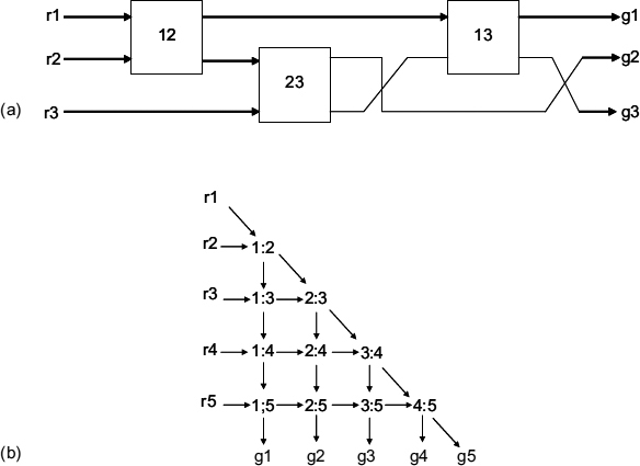
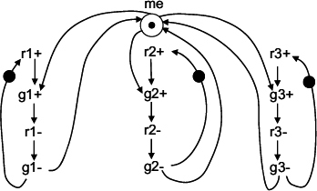
The idea of a mesh is quite simple. A two-way MUTEX is used for constructing arbitrating combinations on the 2-of-n basis. The example of a three-way MUTEX, consisting of three two-way MUTEXes is shown in Figure 13.1(a). The reader can easily check that this circuit correctly, in a speed-independent manner, implements its STG specification shown in Figure 13.2. Similarly, for n = 4 (5, …) one would need 6 (10, …) two-way MUTEXes, and so on. There could be many possible solutions for arbitrary n, depending on the requirements to the graph layout. For example, one possible layout could be obtained from the triangle under the main diagonal of the n × n matrixes shown in Figure 13.1(b). This layout is regular and avoids mutual crossing of interconnects between MUTEXes. It is easy to see that the complexity of the mesh architecture grows quadratically with the number of inputs n, which is certainly not economical. Morever, the latency, i.e. the propagation delay is proportional to n, which is also rather large.
This architecture is therefore not very popular if one needs to build an arbiter for sufficiently large n. However, for small values of n, such as 3 or even 4, this structure is quite practical, given that other topologies such as tree or ring require certain time and overhead due to the need for additional logic in the interface between the request–grant channels and the MUTEXes.
Figure 13.1 (a) Pair-wise mesh interconnection for three-way MUTEX; (b) idea for a regular layout.
Figure 13.2 STG for a three-way MUTEX.
13.2 CASCADED TREE ARBITERS
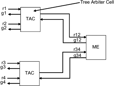
Cascaded multi-way arbiters are based on a tree topology, in which the front end requests arbitrate in (adjacent) pairs, and then new requests are generated on their behalf. These new requests propagate to the next level of the tree and arbitrate with their neighbour in the same fashion, and so on. Finally, only two requests remain at the root of the tree. This structure is illustrated in Figure 13.3 for the case of n=4. In order to build such a cascaded arbiter for the four-phase (RTZ) signaling scheme, two types of components are required. The basic one is a two-way arbiter, which was introduced in the previous section in Figure 12.6 and 12.7(a). We shall now call it a tree arbiter cell (TAC), in which the channel with the common resource is used to communicate with the higher level. For implementing the cell in the root of the tree, one can simply use a two-way MUTEX. This would give a multi-way MUTEX, where the request–grant protocols have the acquisition and release phase. For a multi-way arbiter that deals with a single resource, the root of the tree should be just another TAC. Here, the task of releasing the resource by the client would be implemented outside the arbiter, via a link between the client and the resource, exactly as it was assumed to be in Figure 12.6. One can build a two-phase (NRZ) version of the tree arbiter in a similar way using the two-way component of Figure 12.7(b).
Figure 13.3 Four-way MUTEX built as a cascaded arbiter.
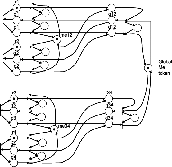
The behaviour of a cascaded arbiter with NRZ signaling, acting as a multi-way RGD arbiter, where both acquisition and release phases propagate through the arbiter, is illustrated in Figure 13.4.
Figure 13.4 Petri net model of a cascaded RGD arbiter.
The analysis of the behaviour of the cascaded arbiter in either RTZ or NRZ form shows a number of important details that can offer a number of options in which the basic design of the arbiter can be modified.
First, the design can be modified by observing that the request produced in the TAC to the next stage (or to the resource in the case of two-way arbitration) does not need to wait until the mutual exclusion between the requests r1 and r2 has been resolved. Such arbiter designs, called low-latency or early-output arbiters, have been implemented in [82,97]. The idea behind such an arbiter can be seen in the STG shown in Figure 13.5.
Second, in the original tree arbiter design after the release of the request by the client, the release propagates all the way back to the root of the tree, regardless of the position where the next request is produced. A modification to that was proposed in a tree arbiter with the nearest-neighbour policy [88]. Here, at every TAC stage of the cascade, when a particular request is released, there is an additional checking of whether there is a request pending from the neighbour. If such request is pending the grant is ‘short-circuited’ at this level directly to the nearest neighbour. This modification, although affecting the fairness of arbitration by delaying the service of other neighbours, improves the throughput of the overall system. Intuitively, such a modification is quite tempting and seems to gain a lot in performance. However, in reality it does not! The detailed analysis of such an arbiter and its comparison with an ordinary (FIFO discipline) tree arbiter was carried out in [88]. This analysis shows that under realistic parameters of the system, such as delays in logic and interconnects and request and service rates (at exponential distribution), the gain in performance is normally only 20–30%, and certainly not a factor of two.
Figure 13.5 STG for a TAC with early output.
13.3 RING-BASED ARBITERS
Ring-based arbitration is usually based on the principle of a token ring. The multi-way arbiter, or better say the multi-way MUTEX because it has both the acquisition and release functions, is built of the nodes connected in a ring. Each node is connected to a client via request and grant lines (and a done line in case of the NRZ signalling for an RGD arbiter). There is no direct connection between the ring and the resource. The resource is represented by a token in the ring. This token can be acquired by the node if the client associated with the node wins the arbitration. Token ring arbitration can be organized in two ways, depending on the behaviour of the token at the time when there are no active requests from clients.
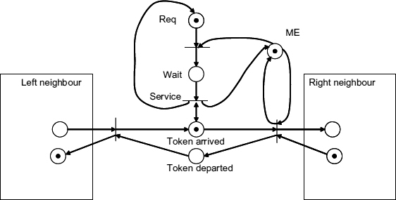
One approach, called a busy token ring or busy ring arbiter, is based on the idea of a token constantly rotating through the ring, visiting the nodes and polling the requests. The Petri net model of such an arbiter is shown in Figure 13.6. Here the place labeled ‘Token arrived’ enables the transition called ‘Service’ only when the Wait place has a token, which is the case when the Request is pending. As soon as the service is finished and the place ME is marked with the token, propagation of the privilege token continues.
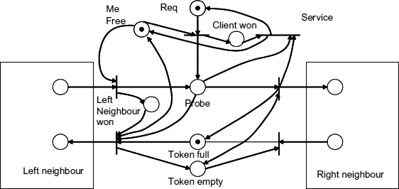
Another approach, called the lazy ring, is based on the idea of keeping the token in the node where the client was the most recent winner. If some other client requests the token the information about this request will propagate to the location of the token and shift the token to the requesting node. Such movements should obviously involve arbitration at every intermediate node with their local requests. The Petri net model of this behaviour is shown in Figure 13.7. Here, the position of the token, whether it is in this node or not, is indicated by the places called ‘Token full’ and ‘Token Empty’. There are four possible scenarios, depending on the state of those places and depending on whether the local request or the request arriving from the left neighbour has won the arbitration in this stage. Consider for example, the situation when the ‘Token empty’ is marked and the winner is the left neighbour. This would cause the request to propagate to the right neighbour. Eventually the bottom transition on the right fires and switches the marking to the ‘Token full’ place. At this point the result of the local arbitration is used, i.e. the place ‘Left neighbour won’ is marked which causes the firing of the bottom left transition. As a result the privilege token has moved to the left and the current stage has returned to the ‘Token empty’ state.
Figure 13.6 High-level model of a busy ring arbiter section.
Figure 13.7 High-level model of lazy ring arbiter section.
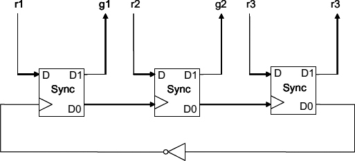
Figure 13.8 Three-way MUTEX implemented as a busy ring arbiter.
An example of possible implementation for the busy ring arbiter is shown in Figure 13.8. The main building block is a Sync synchronizer, which implements a node in the ring. In order to guarantee the appropriate change of the phase of signal an inverter must be included. The RTZ signalling discipline is used here. The request polling action only happens on the rising edge of the token ring signal. The falling edge causes the global release of all the nodes. It could be possible to build a busy ring on the principle of an RTZ between the adjacent nodes, but this would require two handshake signals instead of one.
Figure 13.9 STG model of the lazy ring adaptor.
Figure 13.10 Circuit implementation of the lazy ring adaptor.
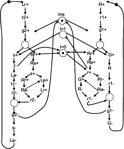
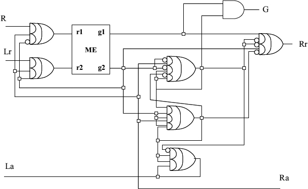
There have been several examples of implementing the lazy ring arbitration. For example, one was called distributed mutual exclusion [98]. Another possible implementation is shown here in the form of an STG for one node of a lazy ring arbiter (called a ring adaptor) in Figure 13.9. The circuit obtained from this STG is shown in Figure 13.10. This circuit was synthesized from this STG using methods described in [107].
The comparison of the busy and lazy ring arbiters has been performed in [89]. It showed that although the busy ring arbiter offers faster response time (its worst-case delay is proportional to the single ring delay while the lazy ring's worst case is twice as much), its excessive power consumption, when the traffic of requests is low, can be too prohibitive. Some hybrid solutions were proposed in [89].

