4
Noise and its Effects
4.1 NOISE
The effect of noise is that the output of a synchronizer becomes nondeterministic with the input close to the balance point, and an individual output time no longer depends primarily on the inputs. This only occurs with very small timing differences, and to understand the effect of a noise signal measured in millivolts it is first necessary to find the relationship between voltage displacement and time. By measuring the initial voltage difference between the two latch outputs in a simulated Jamb latch resulting from very small changes in the overlap of clock and data, the trade-off θ, between time overlaps and equivalent voltage difference can be found.
Actual measurement of the noise is best done using a small DC bias to create a given voltage difference between the nodes rather that a time difference between data and clock signals because external jitter and noise can be filtered out from the DC bias, where it cannot be easily removed from high-bandwidth inputs.
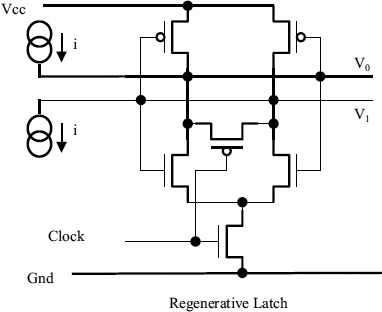
The measurements can be made with the circuit of Figure 4.1. A constant current is fed into one node of a flip-flop and out of the other, so that a small variable bias is imposed between the nodes. Then the flip-flop is activated by continuously clocking while the bias is slowly varied.
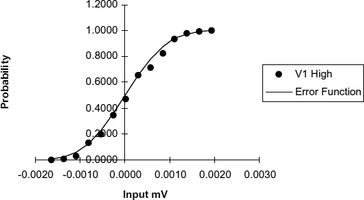
When V0 is very close to V1 at the time the clock goes high, the flip-flop output is determined mainly by thermal noise, since the RMS noise voltage on these nodes is greater than the offset due to the input current i. Under these circumstances the random nature of the output can be clearly observed, and as the input current changes from negative through zero to positive the proportion of V1 high outputs goes from zero to 100%. Plotting the change in this proportion for a given input change against the actual input for one sample of the fabricated devices gives a graph like that of Figure 4.2, where the points measured are compared with an error function curve with an equivalent RMS noise value.
Figure 4.1 Noise measurement circuit.
The origin of noise in CMOS transistors is fluctuations in the drain current due to quantum mechanical effects. These thermal fluctuations give rise to drain current noise and gate noise. Van der Ziel [15] gives drain current noise as
Figure 4.2 Probability of V1 high. Reproduced from Figure 15, “Synchronization Circuit Performance” by D.J. Kinniment, A Bystrov, A.V. Yakovlev, published in IEEE Journal of Solid-State Circuits, 37(2), pp. 202–209 © 2002 IEEE.
where gd0 is the drain–source conductance, and the parameter γ has a value typically between 2 and 3. The equivalent gate noise voltage is approximately
where δ is typically 5–6. The amplitude of the noise is related to the conductance and the bandwidth over which it is measured. In the latch circuit noise at nodes V1 and V0 has a bandwidth limited by the capacitance C to:
By adding the two noise contributions due to Equations (4.1) and (4.2), then putting ![]() a good approximation to the gate noise at each node is obtained as:
a good approximation to the gate noise at each node is obtained as:
Where T is the absolute temperature, and k is Boltzmann's constant, 1.38 × 10⁻²³. This is 0.5–0.6 mV on each node for a 0.6 μ process, but between nodes V1 and V0 it is ![]() greater, or about 0.8 mV. A measurement of approximately 0.8 mV RMS corresponds to a time difference of about 0.1 ps at the inputs of a Jamb latch. It is interesting to note that as the dimensions of the device reduce, the effects of noise become greater, with a 60 nm process giving three times the noise voltage. If the supply voltage is also reduced by a factor of three, the effects of noise are also greater, so that the time differences at which indeterminacy starts are around 0.3 ps unless the transistor W/L ratios are increased to give a higher value of C.
greater, or about 0.8 mV. A measurement of approximately 0.8 mV RMS corresponds to a time difference of about 0.1 ps at the inputs of a Jamb latch. It is interesting to note that as the dimensions of the device reduce, the effects of noise become greater, with a 60 nm process giving three times the noise voltage. If the supply voltage is also reduced by a factor of three, the effects of noise are also greater, so that the time differences at which indeterminacy starts are around 0.3 ps unless the transistor W/L ratios are increased to give a higher value of C.
Intuitively it seems that a latch cannot remain in metastability in the presence of random noise, and because it gets knocked off balance, the metastability time will be shortened. In a typical synchronizer application, this is not the case. Couranz and Wann [16], have demonstrated both theoretically and experimentally that for a uniform distribution of initial condition voltages, as would be the situation for the histograms presented here, the probability of escape from metastability with time does not change with the addition of noise, but only if we assume a uniform distribution of initial conditions. For each noise contribution that moves a trajectory away from metastability, there will, on average, be another compensating noise contribution that moves a trajectory towards metastability.
4.2 EFFECT OF NOISE ON A SYNCHRONIZER
To show how this happens, let us assume a normal distribution of noise voltages such that the probability of a noise voltage being within dυ1 of υ1 is
Here the RMS noise voltage is en, and the probability of the noise voltage being somewhere between −∞ and +∞ is
Further, we will assume for a normal synchronizer that the probability of a particular initial difference Kb being within dυ of υ is
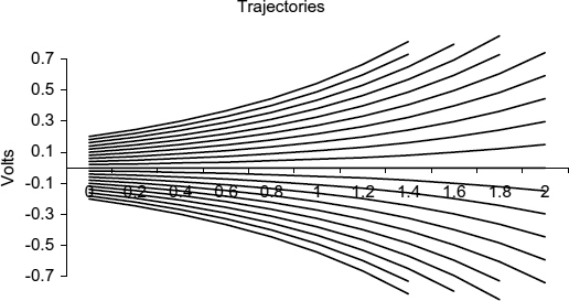
where V is the range of voltages over which the probability is constant. If the probability density of the initial voltage difference is constant, then the probability density of the trajectories at any time is also constant. This can be seen by observing that the trajectories cross both the X = 0.1 line and the X = 1.1 line at different, but regular spacing in Figure 4.3.
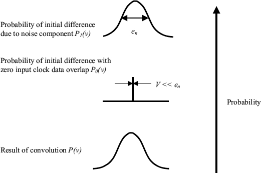
We convolve these two to get the resulting probability density of initial differences at the latch nodes.
Figure 4.3 Uniformly spaced trajectories.
In a normal synchronizer P0(υ − υ1) is a constant over a range much wider than the noise voltage, ![]() , so it can be taken outside the integral
, so it can be taken outside the integral
The final probability density is also constant,
and the result is nearly the same as the one we started with.
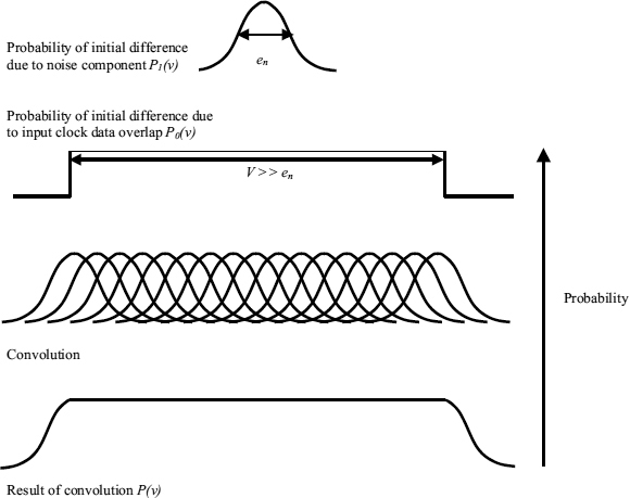
The process of convolution is illustrated in Figure 4.4, where the noise distribution P1(υ), is convolved with the initial difference distribution P0(υ), to produce the result P(υ). In fact it does not matter much that we used a Gaussian distribution of noise voltages, any other distribution with negligible probability outside −V/2 and +V/2 would give a similar result.
4.3 MALICIOUS INPUTS
4.3.1 Synchronous Systems
Sometimes clock and data can become intentionally, or unintentionally locked together so that the data available signal always changes at exactly the same relative time. If this time is the balance point of the latch, the input is called a malicious input, and metastability times could become very long were it not for the presence of noise.
Figure 4.4 Convolution with noise voltage.
For a malicious input the initial difference voltage between the nodes is always 0 V, and the situation is very different from a normal synchronizer because ![]() , so that if υ = 0, P0(0) = 1, and if υ ≠ 0 P0(υ) = 0. Looking at the two cases separately, when V1 = υ
, so that if υ = 0, P0(0) = 1, and if υ ≠ 0 P0(υ) = 0. Looking at the two cases separately, when V1 = υ
Otherwise P1(υ1) P0(υ − υ1) = 0
This means that
So the result of adding noise to an initial time difference between clock and data difference that is always equal to the balance point, is to produce a distribution of initial differences equal to the noise distribution. This is the intuitively obvious result shown in Figure 4.5, in which the noise has the effect of knocking the metastability off balance so that it resolves quicker.
Figure 4.5 Malicious input.
The effect of noise on the average metastability time is now determined by the probability of the initial difference being near the balance point, so it is possible to compute the MTBF for a synchronizer in a typical application where all values of data to clock times are equally probable. This was shown to be

in Equation (2.10). For the case where the initial difference is determined solely by noise, the probability of a long metastable time where Kb is less than Vx is given by the number of clocks in time T, multiplied by the probability of a noise voltage less than Vx or
This gives
Comparing the two formulae, (Equations 2.10 and 4.14) it can be seen that fd no longer appears in (4.14) because the data is assumed to change at exactly the same time as the clock. Tw is associated with input conditions, which do not now determine the input time, and the noise allows the flip-flop to resolve quicker, larger noise voltages giving longer MTBF, and no noise meaning zero MTBF.
As an example, if Tw = 10 ps, en = 0.8 mV, and fc, fd = 100 MHz, a normal synchronizer would have an MTBF of ![]() , where one with a malicious input would have an MTBF of
, where one with a malicious input would have an MTBF of ![]() .
.
To get the reliability for a synchronizer with a malicious input to be the same as the normal synchronizer reliability with a uniform distribution of clock-data overlaps we would need a τ. ln[10−5/2.10−10] = 11 τ, longer synchronization time.
A value of en = 0.8 mV, or 0.1 ps time variation, would represent the effects of internal thermal noise only. In practice jitter on the clock or data of a small system might be 4 ps, and in a large system 20 ps clock jitter would not be unusual. If this jitter has a Gaussian distribution it would be sufficient to add
to the synchronization time in order to get the same reliability.
4.3.2 Asynchronous Systems
In an asynchronous system arbitration is subject to delay due to metastability, but if the relative timing of the competing requests is uniformly distributed as described in Section 3.6, the average additional delay from this cause is only τ. In many systems the requests are not uniformly distributed, for example in a pipelined processor where both instructions and operands generate requests from different parts of the pipeline to the same cache memory. In this case the dynamics of the system may cause both requests to collide frequently, and in the worst case, always at similar times. In this worst-case situation jitter and noise could spread the request spacing over a range of, say, 5 ps rather than exactly zero every time.
The time taken by the MUTEX to resolve can be obtained from Equation (2.7) and is
If the time variation due to jitter and noise is Tn, we need to average the response time over the range 0 to Tn, that is:
The result of averaging is:
So if the noise is as wide or wider than the metastability window, the extra time is still only τ, but if it is much less, for example if Tw is 100 ps, and Tn as low as 5 ps, the average time might be 4 τ rather than τ.
Synchronization and Arbitration in Digital Systems D. Kinniment
© 2007 John Wiley & Sons, Ltd

